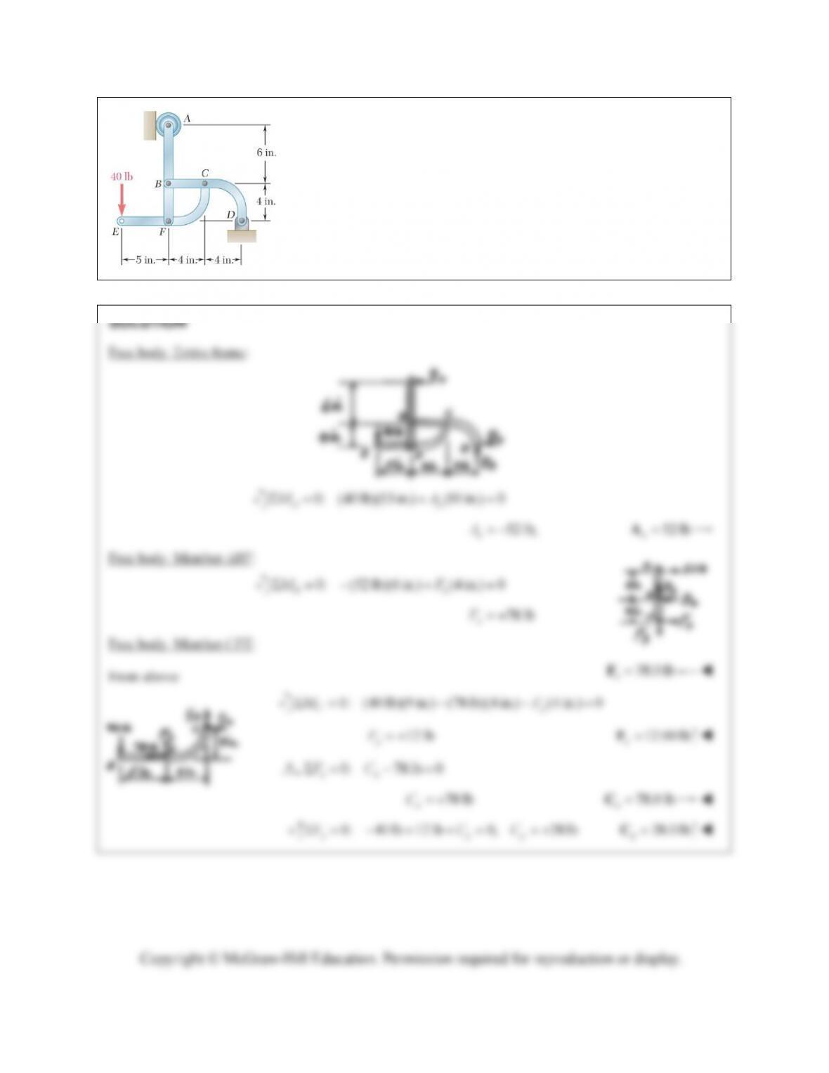
PROBLEM 6.171
For the frame and loading shown, determine the components of the
forces acting on member CFE at C and F.
Copyright © McGraw-Hill Education. Permission required for reproduction or display.
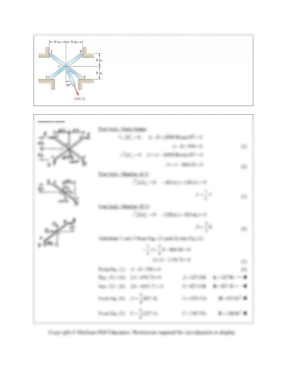
PROBLEM 6.172
For the frame and loading shown, determine the reactions at A, B, D,
and E. Assume that the surface at each support is frictionless.
Copyright © McGraw-Hill Education. Permission required for reproduction or display.
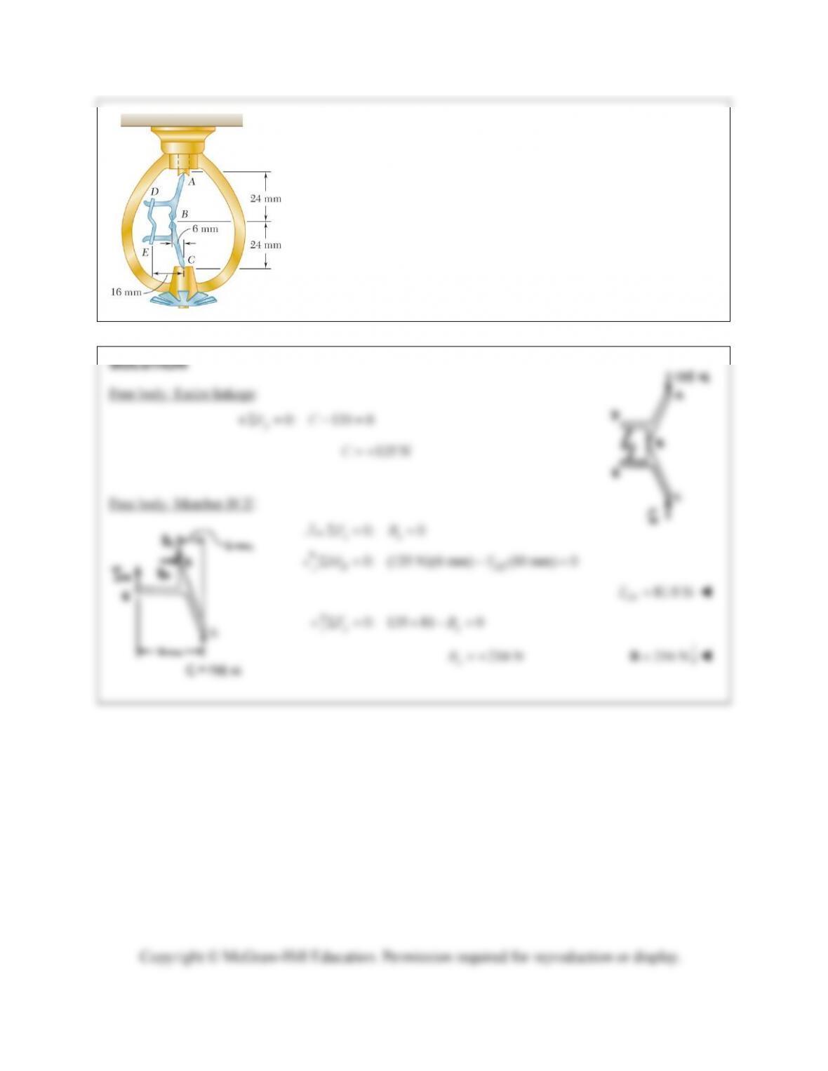
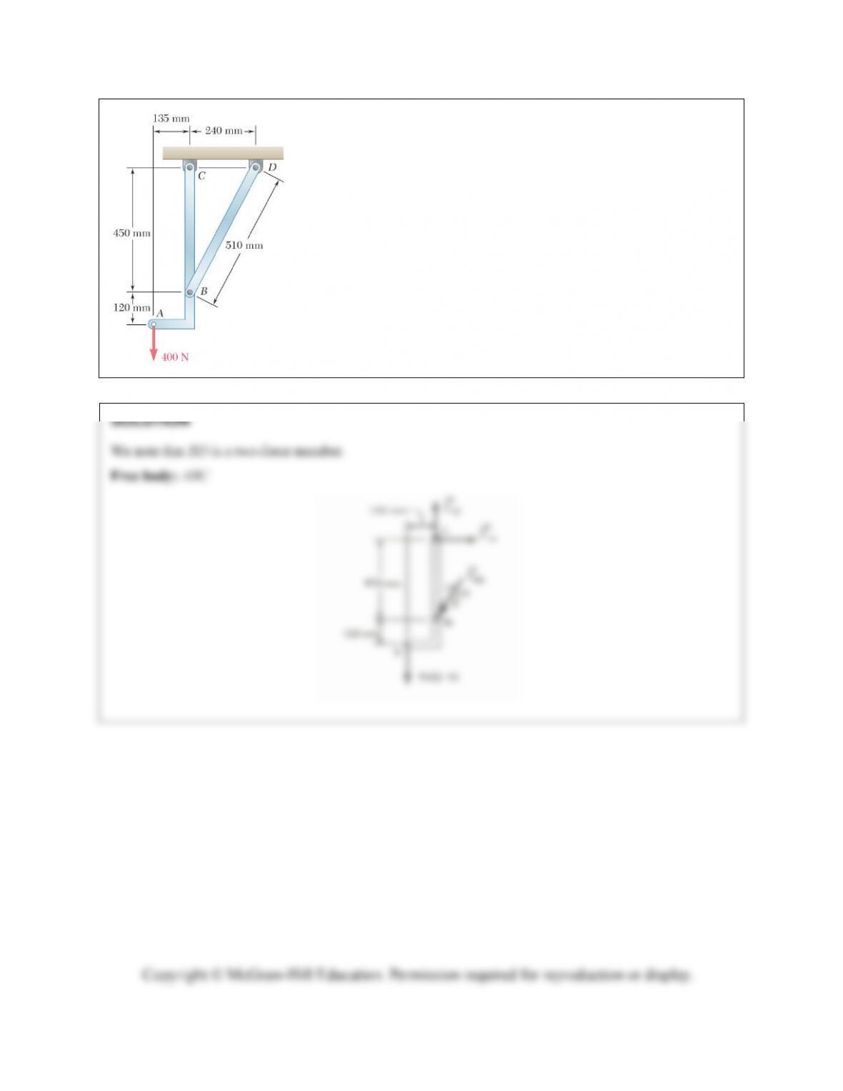
PROBLEM 6.173
Water pressure in the supply system exerts a downward force of 135 N
on the vertical plug at A. Determine the tension in the fusible link DE
and the force exerted on member BCE at B.
Copyright © McGraw-Hill Education. Permission required for reproduction or display.
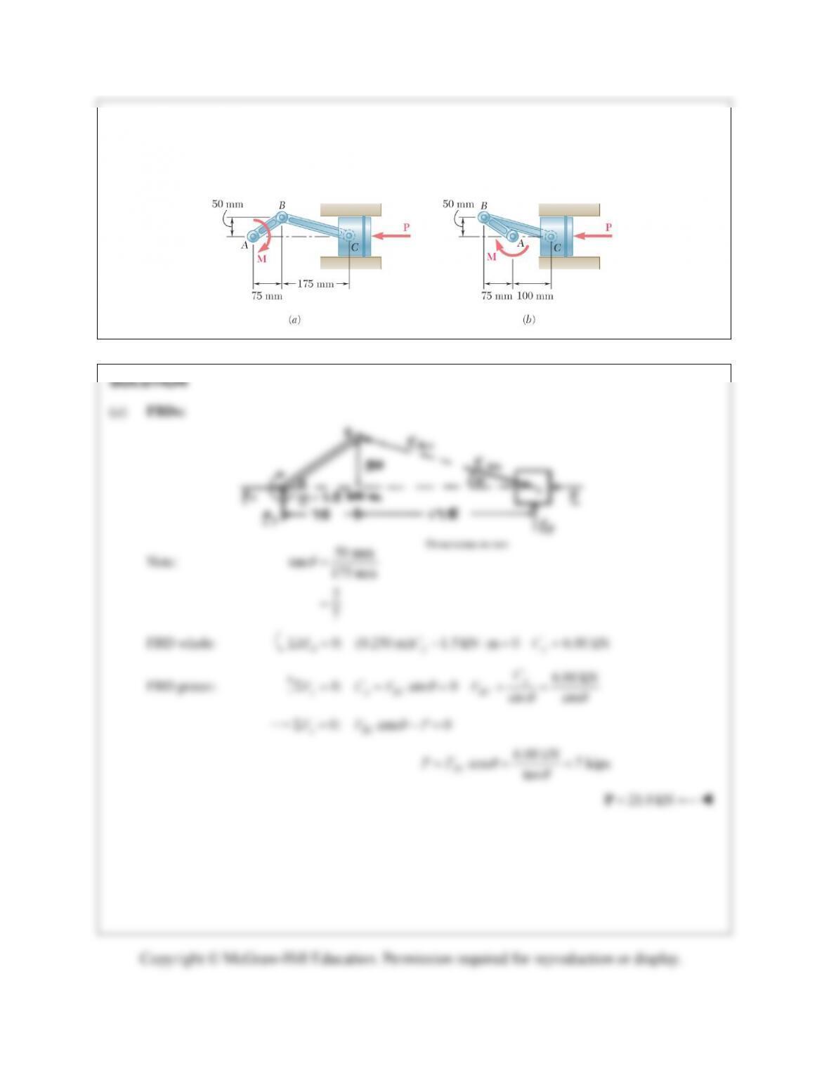
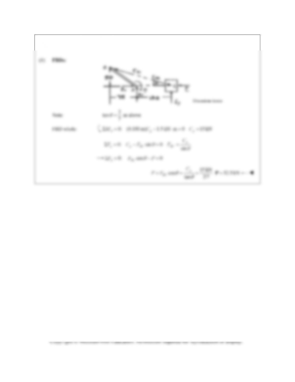
PROBLEM 6.174
A couple
M
of magnitude 1.5 kN m is applied to the crank of the engine system shown. For each of the
two positions shown, determine the force
P
required to hold the system in equilibrium.
Note:
50 mm
tan 175 mm
2
7
FBD whole:
0: (0.250 m) 1.5 kN m 0 6.00 kN
Ay y
MC C
FBD piston:
6.00 kN
0: sin 0 sin sin
y
y y BC BC
C
FCF F
0: cos 0
xBC
FF P
6.00 kN
cos 7 kips
tan
BC
PF
21.0 kN
P
PROBLEM 6.174 (Continued)
Note: 2
tan as above
7
FBD whole:
0: (0.100 m) 1.5 kN m 0 15 kN
Ay y
MC C
0: sin 0 sin
y
y y BC BC
C
FCF F
0: cos 0
xBC
FF P
15 kN
cos tan 2/7
y
BC
C
PF
52.5 kN
P
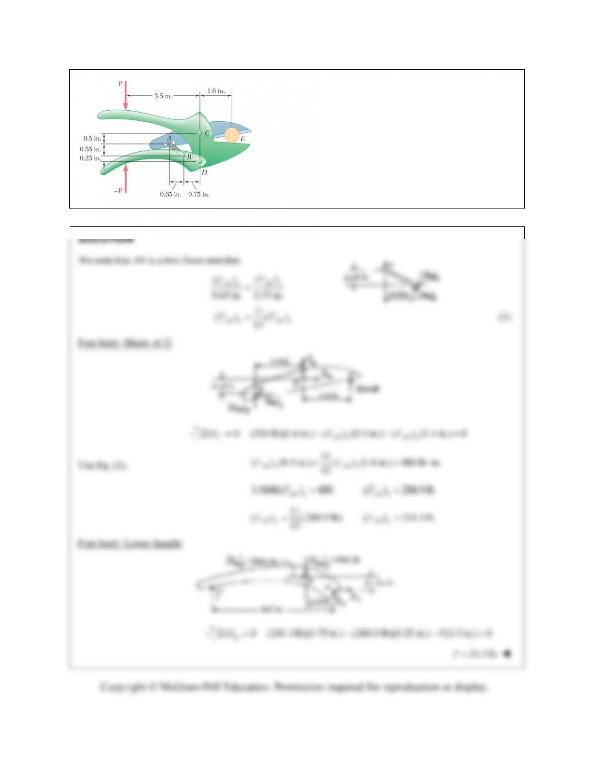
PROBLEM 6.175
The compound-lever pruning shears shown can be
adjusted by placing pin A at various ratchet positions on
blade ACE. Knowing that 300-lb vertical forces are
required to complete the pruning of a small branch,
determine the magnitude P of the forces that must be
applied to the handles when the shears are adjusted as
shown.
PROBLEM 6.F1
For the frame and loading shown, draw the free-body diagram(s) needed
to determine the force in member BD and the components of the reaction
at C.
Copyright © McGraw-Hill Education. Permission required for reproduction or display.
PROBLEM 6.F2
For the frame and loading shown, draw the free-body diagram(s)
needed to determine the components of all forces acting on
member ABC.
Copyright © McGraw-Hill Education. Permission required for reproduction or display.
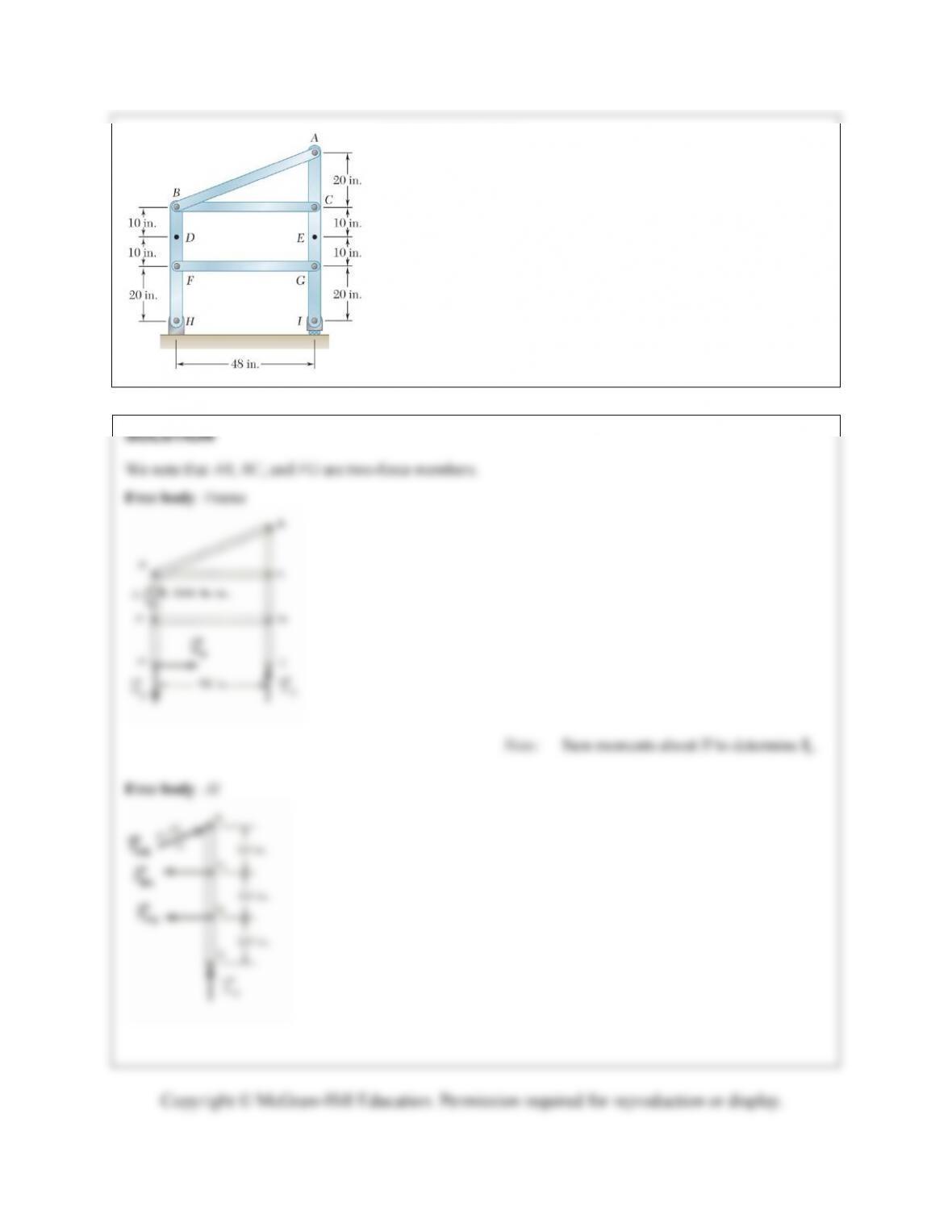
PROBLEM 6.F3
Draw the free-body diagram(s) needed to determine all the forces
exerted on member AI if the frame is loaded by a clockwise
couple of magnitude 1200 lb·in. applied at point D.
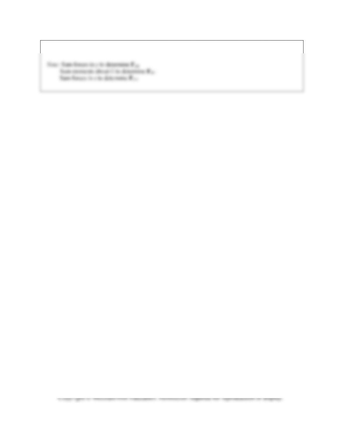
PROBLEM 6.F3 (Continued)