PROBLEM 6.26
Solve Problem 6.24 assuming that the cables
hanging from the right side of the tower have
fallen to the ground.
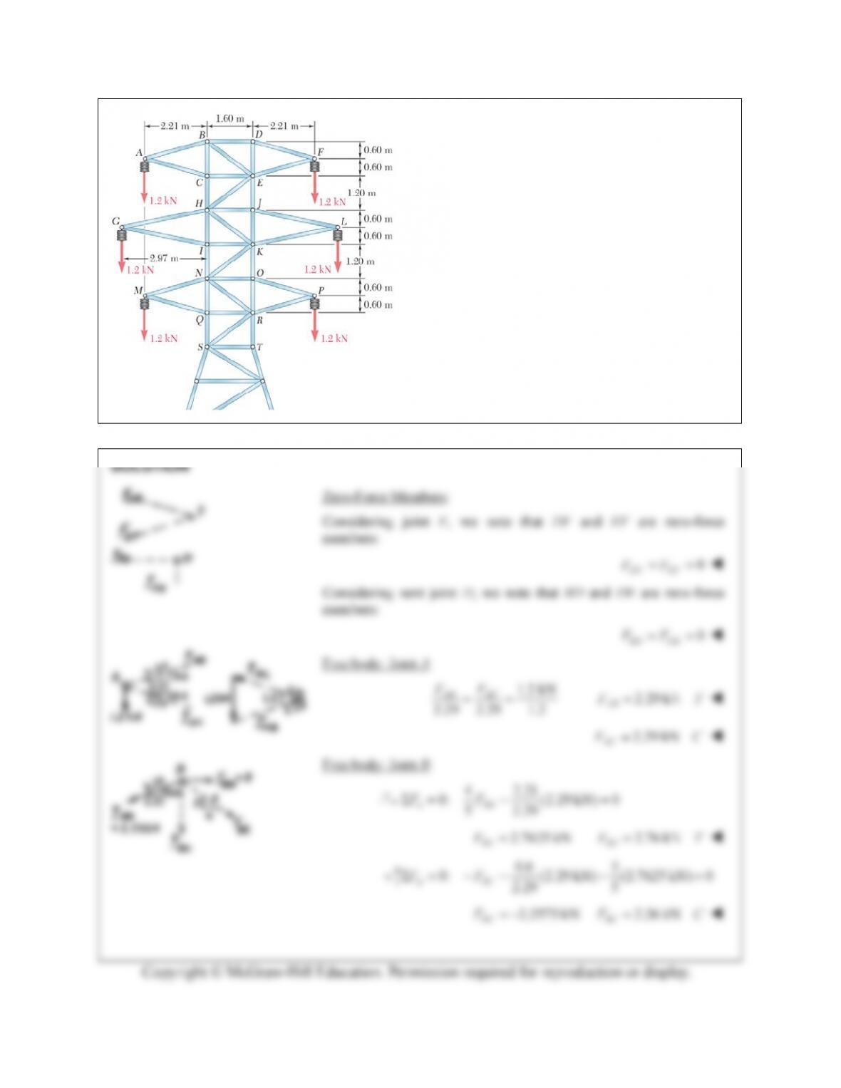
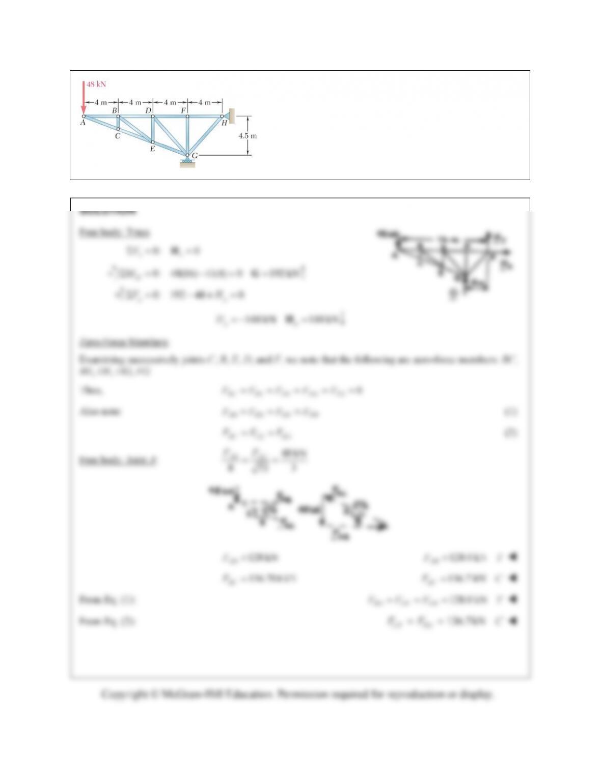
PROBLEM 6.24 The portion of truss shown
represents the upper part of a power transmission
line tower. For the given loading, determine the
force in each of the members located above HJ.
State whether each member is in tension or
compression.
PROBLEM 6.26 (Continued)
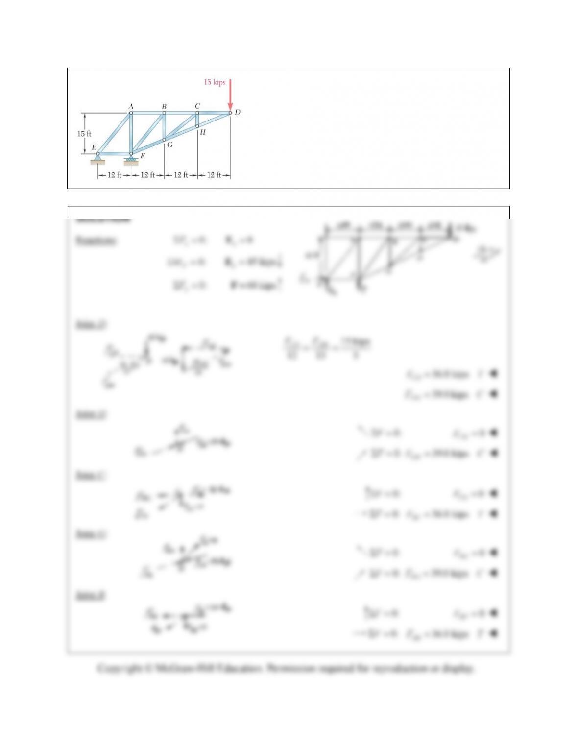
PROBLEM 6.27
Determine the force in each member of the truss shown.
State whether each member is in tension or compression.
PROBLEM 6.27 (Continued)
PROBLEM 6.28
Determine the force in each member of the truss shown.
State whether each member is in tension or compression.
PROBLEM 6.28 (Continued)
FH
PROBLEM 6.29
Determine whether the trusses of Problems 6.31a,
6.32a, and 6.33a are simple trusses.
PROBLEM 6.30
Determine whether the trusses of Problems 6.31b, 6.32b, and 6.33b are simple trusses.
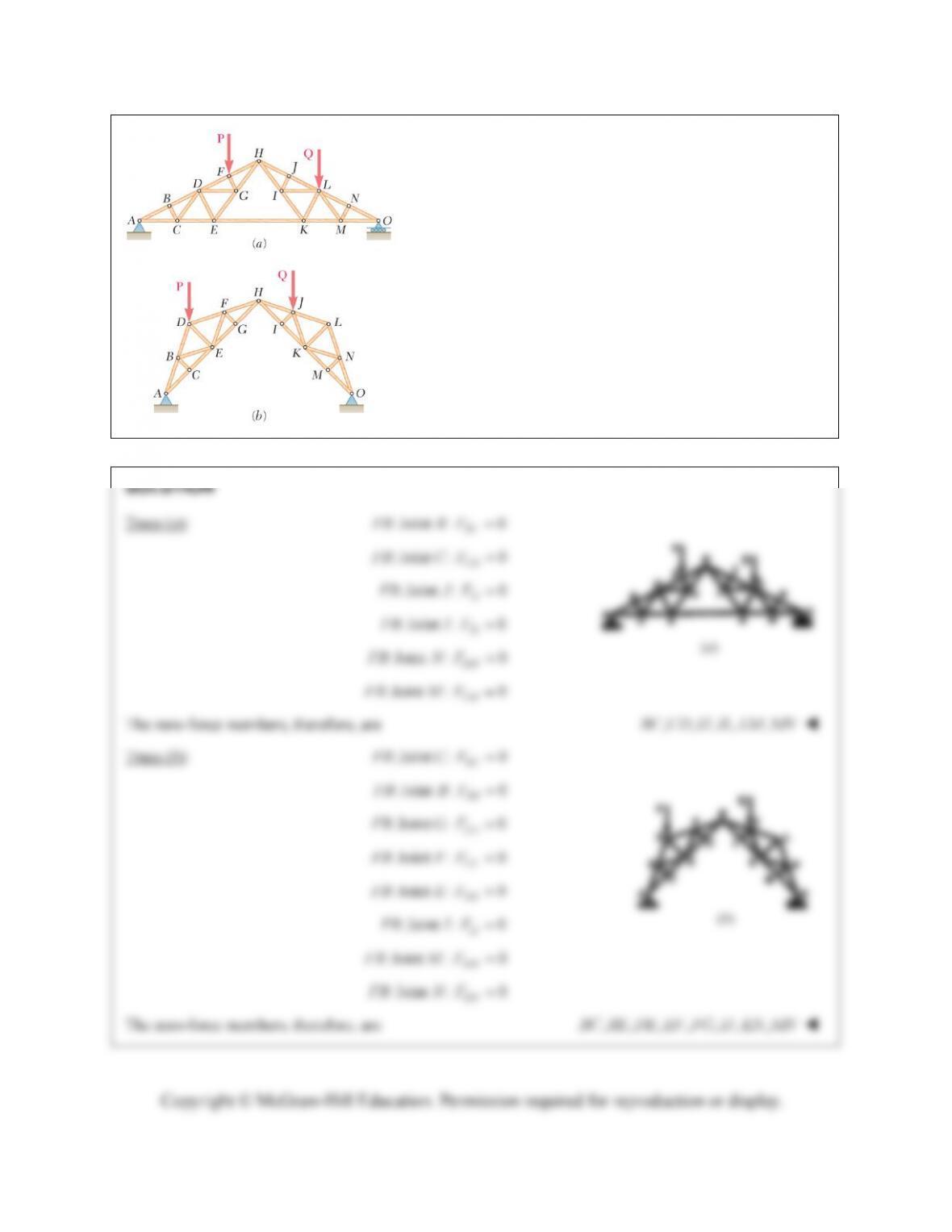
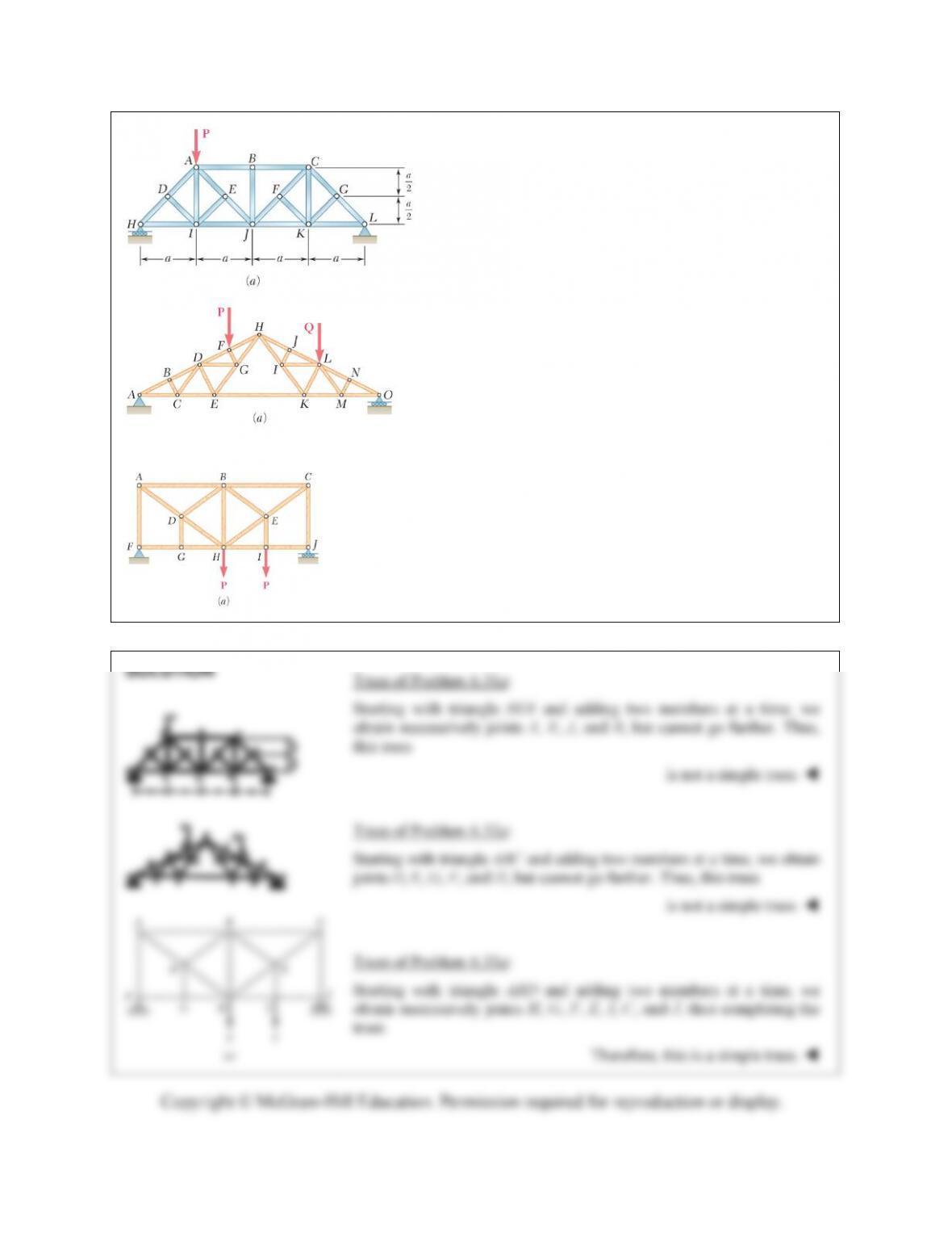
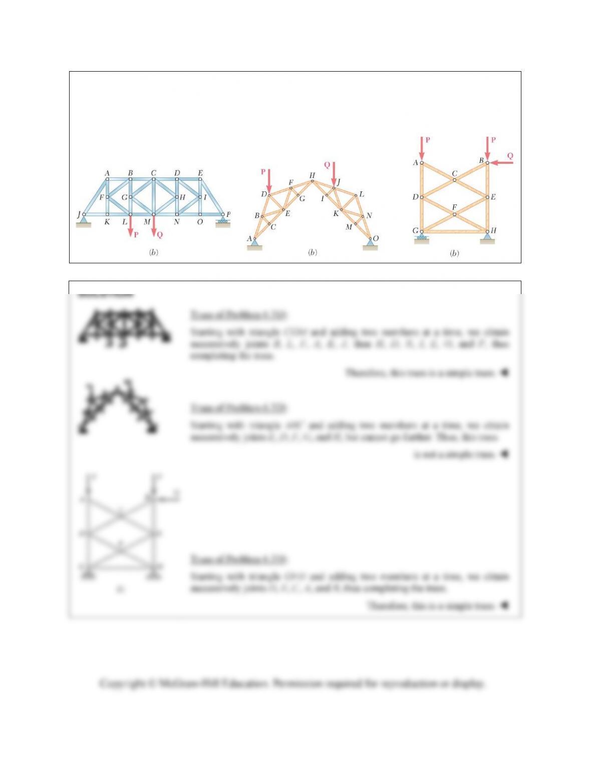
PROBLEM 6.31
For the given loading, determine the zero-force members in
each of the two trusses shown.
:Joint : 0
IJ
FB I F
:Joint : 0
MN
FB M F
: Joint : 0
KN
FB N F
The zero-force members, therefore, are
,,,,,, ,BC BE DE EF FG IJ KN MN
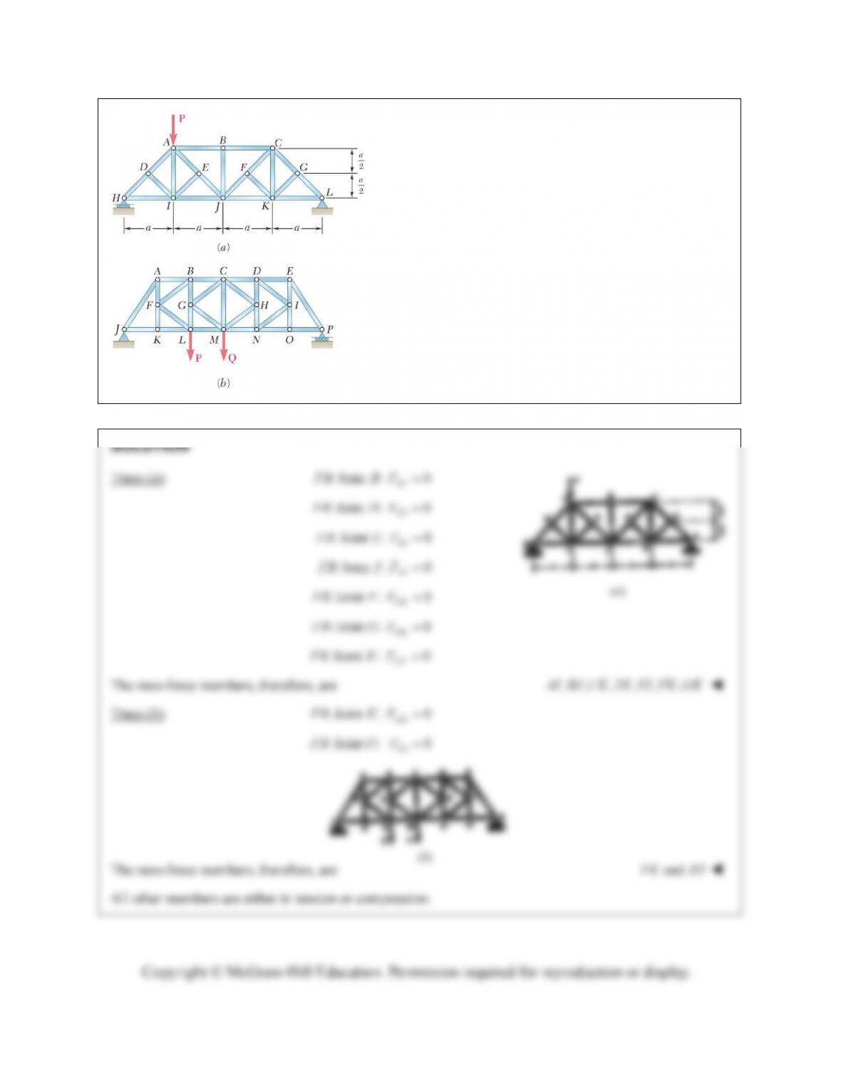
PROBLEM 6.32
For the given loading, determine the zero-force members
in each of the two trusses shown.
:Joint : 0
FK
FB F F
:Joint : 0
GK
FB G F
: Joint : 0
CK
FB K F
The zero-force members, therefore, are
,, ,,, ,AI BJ CK DI EI FK GK
Truss (b): : Joint : 0
FK
FB K F
: Joint :FB O
0
IO
F
The zero-force members, therefore, are
andFK IO
All other members are either in tension or compression.
(b)