Archives
Mechanical Engineering Chapter 1 Homework Evaluate each of the following to three significant
1 2 *1–12. Evaluate each of the following to three significant figures and express each answer in SI units using an appropriate prefix: (a) (b) (c) (2.68 mm)(426 Mg). 128 ms210.0458 Mm2>1348 mg2,1684 mm2>143 ms2, SOLUTION a) Ans. b) Ans. […]
Mechanical Engineering Chapter 1 Homework Represent each of the following as a number between 0.1
1 1–1. What is the weight in newtons of an object that has a mass of (a) 8 kg, (b) 0.04 kg, and (c) 760 Mg? SOLUTION (a) W=9.81(8) =78.5 N Ans. (b) W = 9.81(0.04) ( 10 –3 ) […]
Mechanical Engineering Chapter 10 Homework parallel to the x axis shown shaded in Fig
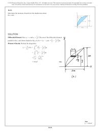
1030 10–21. Determine the moment of inertia for the shaded area about the x axis. SOLUTION Differential Element. Here x2=y and x1= 2 parallel to the x axis shown shaded in Fig. a is dA =(x2–x1)dy = a 1 b […]
Mechanical Engineering Chapter 10 Homework The coordinates of the centroid for this element
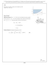
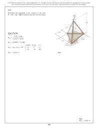
1070 10–61. Determine the product of inertia of the shaded area with respect to the x and y axes. SOLUTION Differential Element: Here, x=2y 1 2. The area of the differential element parallel to the x axis is dA =xdy=2y […]
Mechanical Engineering Chapter 10 Homework The Mass Moment Inertia The Wheel About
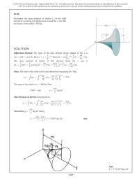
1107 10–94. SOLUTION Differential Element:The mass of the disk element shown shaded in Fig. ais .Here,.Thus,. The mass moment of inertia of this element about the yaxis is . dIy= 1 2dmr2= 1 2 A rpr2dy B r2= rp 2r4dy […]
Mechanical Engineering Chapter 10 Homework The moment of inertia about the y axis for each segment can
© 2016 Pearson Education, Inc., Upper Saddle River, NJ. All rights reserved. This material is protected under all copyright laws as they currently exist. No portion of this material may be reproduced, in any form or by any means, without […]
Mechanical Engineering Chapter 10 Homework Total Mass Performing The Integration Have 200
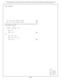
1090 I max = + 2 = = 135 81 2 249.55 in4 250 in4 Ans. I min = – 2 = = 135 81 2 20.44 in4 20.4 in4 Ans. The orientation of the principal axes can be determined […]
Mechanical Engineering Chapter 10 Homework Moment of Inertia. Perform the integration,
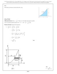
1010 Ans: Ix= ab3 + 3(3n 1) SOLUTION Differential Element. Here x= a b 1 n y 1 n. The area of the differential element parallel to the x axis shown shaded in Fig. a is dA =(a–x)dy = a […]
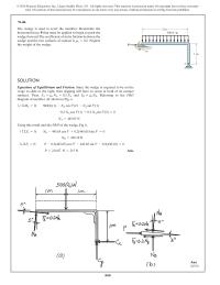
Mechanical Engineering Chapter 11 Homework The crankshaft is subjected to a torque of M = 50 N
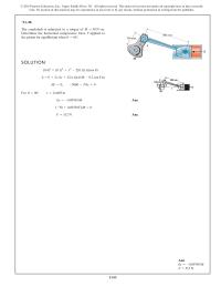
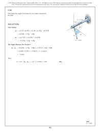
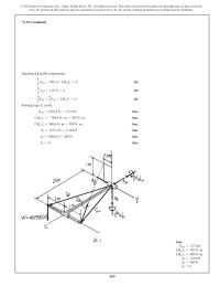
1143 *11–20. The crankshaft is subjected to a torque of Determine the horizontal compressive force Fapplied to the piston for equilibrium when u=60°. M=50 N #m. SOLUTION For Ans. Ans.F=512 N (–50 +0.09769F)du =0 dx=-0.09769 du u=60°, x=0.4405 m dU=0; […]
Mechanical Engineering Chapter 2 Homework Ab Determine The length The Cable And Express
122 2–101. The two mooring cables exert forces on the stern of a ship as shown. Represent each force as a Cartesian vector and determine the magnitude and coordinate direction angles x 30 ft A B uCB =rCA rCA =50i+50j–30k […]
Mechanical Engineering Chapter 2 Homework Choose Value Such That
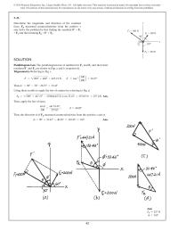
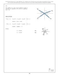
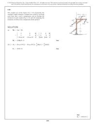
102 2–81. If the coordinate direction angles for are , and , determine the magnitude and coordinate direction angles of the resultant force acting on the eyebolt. g3=45°b3=60° a3=120°F3 SOLUTION Force Vectors: By resolving , and into their x,y, and […]
Mechanical Engineering Chapter 2 Homework Find the magnitude and coordinate direction angles of
8 2 2–61. T h e b o l t i s su bj ecte d to t h e force F,w hi c h h as components acting along the x, y, zaxes as shown. If the magnitude of […]
Mechanical Engineering Chapter 2 Homework No portion of this material may be reproduced
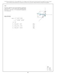
142 2–121. Determine the angle between the two cables attached to the pipe. u SOLUTION 60 y 30 30 x F 1 30 lb =-0.7071i+0.5j+0.5k uF2=cos 135°i+cos 60°j+cos 60°k =0.4330i+0.75j–0.5k uF1=cos 30° sin 30°i+cos 30° cos 30°j–sin 30°k z 60 […]
Mechanical Engineering Chapter 2 Homework No portion of this material may be reproduced, in any form or by any means
4 2 Ans: FR=257 N f =163° SOLUTION Parallelogram Law. The parallelogram law of addition for F1 and F2 and then their resultant F′ and F3 are shown in Figs. a and b, respectively. Trigonometry. Referring to Fig. c, F′= […]
Mechanical Engineering Chapter 2 Homework Solution Parallelogram Law The Parallelogram Law Addition
© 2016 Pearson Education, Inc., Upper Saddle River, NJ. All rights reserved. This material is protected under all copyright laws as they currently exist. No portion of this material may be reproduced, in any form or by any means, without […]
Mechanical Engineering Chapter 2 Homework The directional angle u measured counterclockwise
6 2 Ans: FR=12.5 kN u=64.1° SOLUTION Scalar Notation. Summing the force components along x and y axes algebraically by referring to Fig. a, S + R x=Σ x (F ) F ; (FR)x=4+5 cos 45°–8 sin 15°=5.465 kN S […]
Mechanical Engineering Chapter 3 Homework Assuming that the tension in cable BD reaches the limit
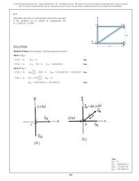
161 3–1. SOLUTION Solving: Ans. Ans.F1=1.83 kN F2=9.60 kN 0.3420F2–0.8660F1=1.7 +c©Fy=0; F2cos 70° +5 sin 30° –F1sin 60° –3 5(7) =0 0.9397F2+0.5F1=9.930 : +©Fx=0; F2sin 70° +F1cos 60° –5 cos 30° –4 5(7) =0 F1 7 kN 4 The members […]
Mechanical Engineering Chapter 3 Homework The street-lights at A and B are suspended
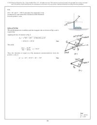
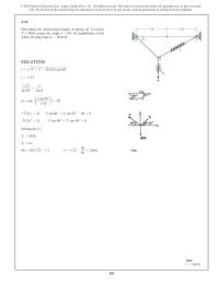
181 3–21. Determine the unstretched length of spring AC if a force causes the angle for equilibrium. Cord AB is 2 ft long.Take k=50 lb>ft. u=60°P=80 lb SOLUTION Solving for , Ans.l=212 –40 50 =2.66 ft40 =50(212 –l¿) F s=kx […]
Mechanical Engineering Chapter 3 Homework We can express each of the forces on the free-body
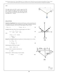
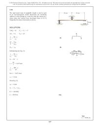
201 3–41. The single elastic cord ABC is used to support the 40-lb load.Determine the position xand the tension in the cord that is required for equilibrium. The cord passes through the smooth ring at Band has an unstretched length […]
Mechanical Engineering Chapter 3 Homework We can express each of the forces shown in Fig
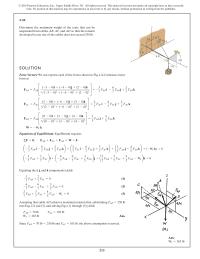
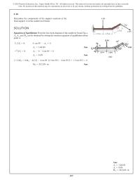
215 3–55. SOLUTION Force Vectors: We can express each of the forces shown in Fig. ain Cartesian vector form as Equations of Equilibrium: Equilibrium requires Equating the i,j,and kcomponents yields (1) (2) (3) 2 7 F AB +3 7 F […]
Mechanical Engineering Chapter 4 Homework It can act at any point on the beam
288 Ans: MAB =136 N #m SOLUTION uAB = {3.5i+0.5j} 2 + (3.5)2 (0.5)2 uAB ={0.9899i+0.1414j} MAB =uAB # ( ) † – – † rAD *F = 0.9899 0.1414 0 2.5 0 4 50 20 80 MAB =136 N […]
Mechanical Engineering Chapter 4 Homework P6 The End The 8mlong Crane Boom
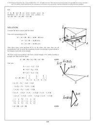
228 4–1. If A , B ,an d D are g i ven vectors, prove t h e distributive law for the vector cross product, i.e., .A:(B+D)=(A:B)+(A:D) SOLUTION Consider the three vectors; with A vertical. Note obd is perpendicular to […]
Mechanical Engineering Chapter 4 Homework Point Summing The Forces Along The Axis
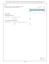
383 Ans: F R= T 51.0 kN d=17.9 m 4–151. SOLUTION Equivalent Resultant Force: Ans. F R=51.0 kN T +cF R=©F y;–F R=-22.5 –13.5 –15 Location of Equivalent Resultant Force: a Ans.d=17.9 m +(MR)O=©MO;–51.0(d)=-500 –22.5(5) –13.5(9) –15(12) O 7.5 m […]
Mechanical Engineering Chapter 4 Homework Replace these forces by an equivalent force and couple
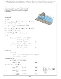
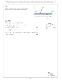
328 Ans: FR=294 N u=40.1° d MRO =39.6 N #m b SOLUTION d + FRx =ΣFx ; FRx =450 sin 30°=225.0 + T F =ΣF ; Ry y F =450 cos 30°–200 =189.7 Ry F R=2 + = (225)2 (189.7)2 […]
Mechanical Engineering Chapter 4 Homework Specify its magnitude and coordinate direction angles
© 2016 Pearson Education, Inc., Upper Saddle River, NJ. All rights reserved. This material is protected under all copyright laws as they currently exist. No portion of this material may be reproduced, in any form or by any means, without […]
Mechanical Engineering Chapter 4 Homework Summing the forces along the y axis by referring to Fig
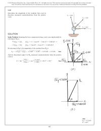
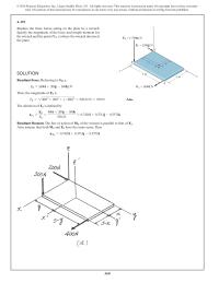
368 SOLUTION Resultant Force. Referring to Fig. a, FR={400i+200j–300k} N Then, the magnitude of FR is F R=2 + + – = = 4002 2002 ( 300)2 538.52 N 539 N Ans. The direction of FR is defined by uFR […]
Mechanical Engineering Chapter 4 Homework The coordinates of point A are
248 Ans: F=27.6 lb 4–21. SOLUTION Resolving force Finto components parallel and perpendicular to the hammer,Fig.a, and applying the principle of moments, a Ans.F=27.6 lb +MA=-500 =-Fcos 30°(18) –Fsin 30°(5) B A F 18 in. 5 in. 30 In order […]
Mechanical Engineering Chapter 4 Homework The figure shows F and MO in an arbitrary position
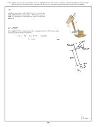
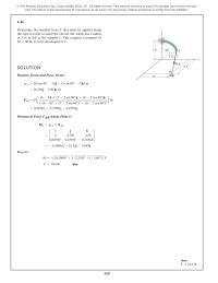
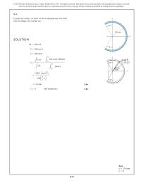
268 Ans: F=18.6 lb 4–41. Determine the smallest force Fthat must be applied along the rope in order to cause the curved rod, which has a radius of 5 ft, to fail at the support C.This requires a moment of […]
Mechanical Engineering Chapter 4 Homework The Tube Supports The Four Parallel Forces
348 Along AB, a=0. Then Eq (1) becomes 220 b–280(0) =730 b=3.318 m Thus, the intersection point of line of action of FR on AB measured upward from point A is d=b=3.32 m Ans. *4–120. Continued Ans: FR=356 N u=51.8° […]
Mechanical Engineering Chapter 5 Homework Ay and NB can be determined by writing the moment
397 5–10. Determine the components of the support reactions at the fixed support Aon the cantilevered beam. 1.5 m 1.5 m Ax ,Ay ,and MAcan be obtained by writing the moment equation of equilibrium about point A. Ans. Ans. Ans.M […]
Mechanical Engineering Chapter 5 Homework Fa Fb And Then The Rest The
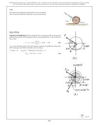
417 Ans: Pmin =271 N SOLUTION Equations of Equilibrium. P will be minimum if its orientation produces the greatest moment about point B. This happens when it acts perpendicular to AB as shown in Fig. a. Thus u=f=cos–1 a0.25 0.3 […]
Mechanical Engineering Chapter 5 Homework If determine the distance hof placement at the end
© 2016 Pearson Education, Inc., Upper Saddle River, NJ. All rights reserved. This material is protected under all copyright laws as they currently exist. No portion of this material may be reproduced, in any form or by any means, without […]
Mechanical Engineering Chapter 5 Homework If it is supported by a ball-and-socket joint at C and
469 *5–76. Continued Equating i, j and k components, 2 7 ( ) FCB +392.4 + MA x=0 (4) – 6 7 FCB +1177.2 =0 (5) – 9 6 ( ) FCB + FCB + MA z=0 (6) 7 7 […]
Mechanical Engineering Chapter 5 Homework The negative signs indicate that Ay, (MA)x
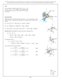
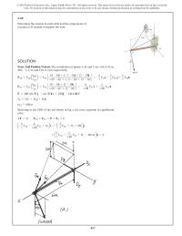
457 SOLUTION Force And Position Vectors. The coordinates of points A, B, and C are A(6, 0, 0) m, B(0, –3, 2) m and C(0, 0, 2) m respectively. FAB =FAB ar b c(0 –6)i+(–3–0)j+(2 –0)k 1 – + – […]
Mechanical Engineering Chapter 6 Homework For this case, compression controls which requires
© 2016 Pearson Education, Inc., Upper Saddle River, NJ. All rights reserved. This material is protected under all copyright laws as they currently exist. No portion of this material may be reproduced, in any form or by any means, without […]
Mechanical Engineering Chapter 6 Homework We will use the above result to analyze the equilibrium of joints Cand A,
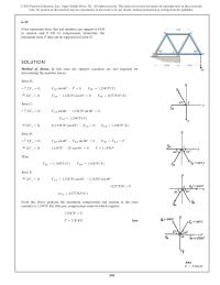
481 SOLUTION Method of Joints. Start at joint C and then proceed to join D. Joint C. Fig. a S + x= ΣF 0; FCB =0 Ans. + c Σ Fy=0; FCD –20 =0 FCD =20.0 kN (C) Ans. Joint […]
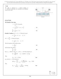
Mechanical Engineering Chapter 7 Homework The Cable Supports The Three Loads Shown
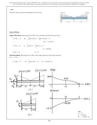
711 *7–92. Draw the shear and moment diagrams for the beam. SOLUTION Support Reactions. Referring to the FBD of the cantilevered beam shown in Fig. a a +ΣMA=0; MA– 1 2 1 2 (6)(1.5)(0.5) – (6)(1.5)(2.5) =0 MA=13.5 kN #m […]
Mechanical Engineering Chapter 7 Homework The negative signs indicates that Nx, Vy, My
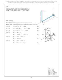
651 7–41. Determine the x, y, zcomponents of force and moment at point Cin the pipe assembly. Neglect the weight of the pipe. dna ekaT F 2 =5–300j+150k6lb.F 1 =5350i–400j6lb F 2 2ft 1.5fty z x C B 3ft F […]
Mechanical Engineering Chapter 7 Homework The Resultant Vertical Force Therefore
© 2016 Pearson Education, Inc., Upper Saddle River, NJ. All rights reserved. This material is protected under all copyright laws as they currently exist. No portion of this material may be reproduced, in any form or by any means, without […]
Mechanical Engineering Chapter 8 Homework Assuming Block Does Not Slipcfy
848 8–102. 50 mm 20 mm C 50 mm a a Ans.F s=85.4 N –F s10.052+125.537 +25.537 sin 30°210.1 cos 45°2+25.537 cos 30°10.1 sin 45°2=0+©MC=0; T 2=65.53 N T 1=25.537 N T 2=T 1e10.321p2=2.5663T 1 T 2=T 1emb; –T 110.022+T […]
Mechanical Engineering Chapter 8 Homework Cand Dare And Mm respectively the Coefficient Static Friction
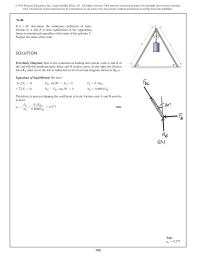
808 *8–60. The wedge is used to level the member. Determine the horizontal force P that must be applied to begin to pushthe wedge forward. The coefficient of static friction between the wedge and the two surfaces of contact is […]
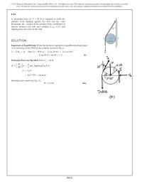
Mechanical Engineering Chapter 8 Homework If slipping does not occur at the wall, determine
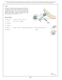
8–94. 841A A minimum force of lb is required to hold the cylinder from slipping against the belt and the wall. Determine the weight of the cylinder if the coefficient of friction between the belt and cylinder is and slipping […]
Mechanical Engineering Chapter 8 Homework The Center Mass For The Skateboard 250
© 2016 Pearson Education, Inc., Upper Saddle River, NJ. All rights reserved. This material is protected under all copyright laws as they currently exist. No portion of this material may be reproduced, in any form or by any means, without […]
Mechanical Engineering Chapter 8 Homework The Coefficient Static Friction Between His Shoes
© 2016 Pearson Education, Inc., Upper Saddle River, NJ. All rights reserved. This material is protected under all copyright laws as they currently exist. No portion of this material may be reproduced, in any form or by any means, without […]
Mechanical Engineering Chapter 9 Homework And Moment Arm The Area The Differential
© 2016 Pearson Education, Inc., Upper Saddle River, NJ. All rights reserved. This material is protected under all copyright laws as they currently exist. No portion of this material may be reproduced, in any form or by any means, without […]
Mechanical Engineering Chapter 9 Homework Determine The Length The Stick That The
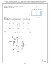
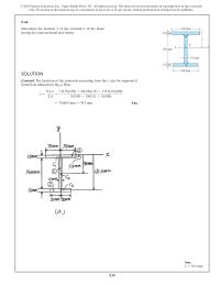
939 9–61. Determine the location y of the centroid C of the beam having the cross-sectional area shown. SOLUTION Centroid. The locations of the centroids measuring from the x axis for segments 1, 2 and 3 are indicated in Fig. […]
Mechanical Engineering Chapter 9 Homework Determine The Location The Centroid For The
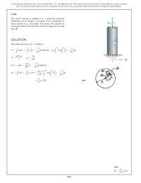
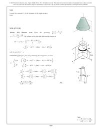
919 9–41. SOLUTION Volume and Moment Arm: From the geometry, The volume of the thin disk differential element is and its centroid z=z. = p h2c1r–R22z2+2Rh1r–R2z+R2h2ddz dV =py2dz =pca1r–R2z+Rh hb2ddz y=1r–R2z+Rh h. R–r=h–z h, Centroid: Applying Eq. 9–5 and performing […]
Mechanical Engineering Chapter 9 Homework Determine The Total Mass The Wheel Mgm3
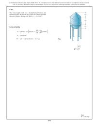
979 9–101. The water-supply tank has a hemispherical bottom and cylindrical sides. Determine the weight of water in the tank when it is filled to the top at C.Take gw=62.4 lb>ft3. SOLUTION Ans.W=gV=62.411357.172=84.7 kip V=1357.17 ft3 V=©urA =2pe3182162+4162 3pa1 4b1p21622f […]
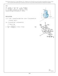
Mechanical Engineering Chapter 9 Homework The Assembly Made From Steel Hemisphere
959 9–81. SOLUTION Ans.z=©zm ©m=9.51425(10–3) 77.7706(10–3) =0.122 m =122 mm =77.7706(10–3)Mg ©m= A 2 3 B p(0.160)3(7.80) +p(0.2)(0.08)2(2.70) =9.51425(10–3)Mg#m ©zm= C 0.160 –3 8(0.160) DA 2 3 B p(0.160)3(7.80) + A 0.160 +0.2 2 B p(0.2)(0.08)2(2.70) y x The assembly […]
Mechanical Engineering Chapter 9 Homework The Factor Safety For Tipping The Concrete
995 *9–116. Continued Ans: FR=27.0 kN x=0.778 m y=0.833 m Thus, x= L A xp(x, y)dA LA p(x, y)dA = 21.0 kN #m 27.0 kN = 7 9 m =0.778 m Ans. y= L A yp(x, y)dA LA p(x, y)dA […]