651
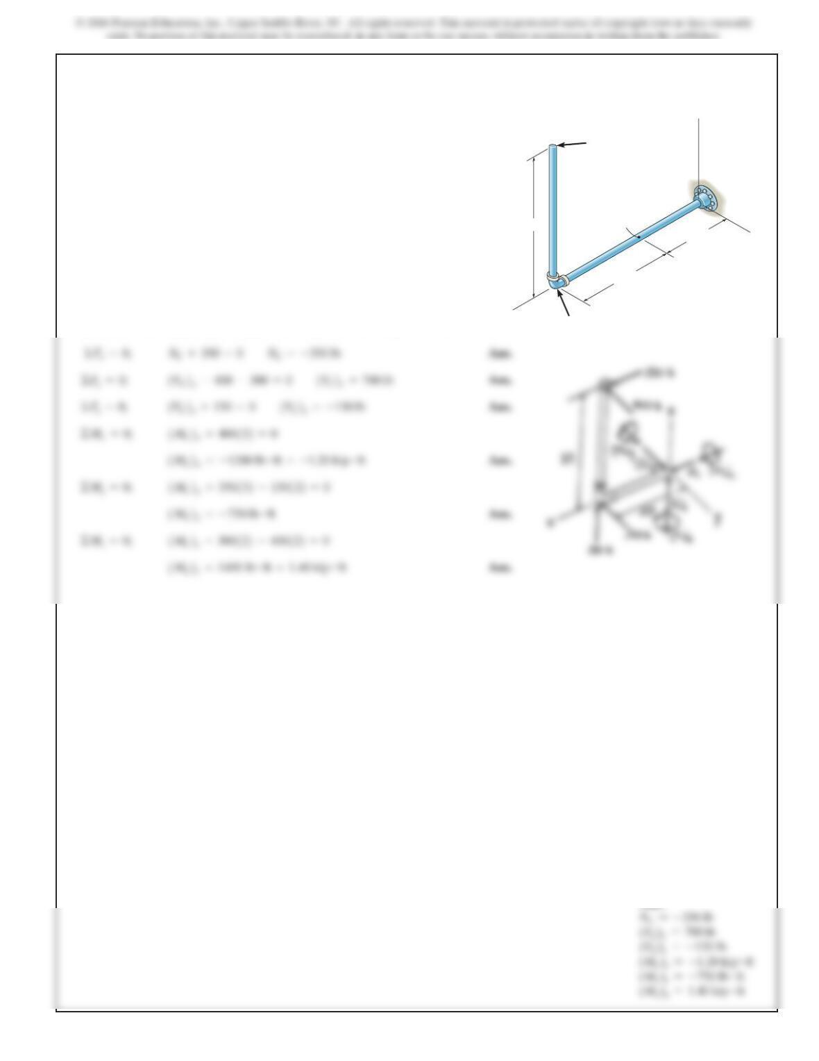
7–41.
Determine the x, y, zcomponents of force and moment at
point Cin the pipe assembly. Neglect the weight of the pipe.
dna ekaT F
2
=5–300j+150k6lb.F
1
=5350i–400j6lb
F
2
2ft
1.5fty
z
x
C
B
3ft
F
1
SOLUTION
Free body Diagram: The support reactions need not be computed.
Internal Forces: Applying the equations of equilibrium to segment BC, we have
Ans:
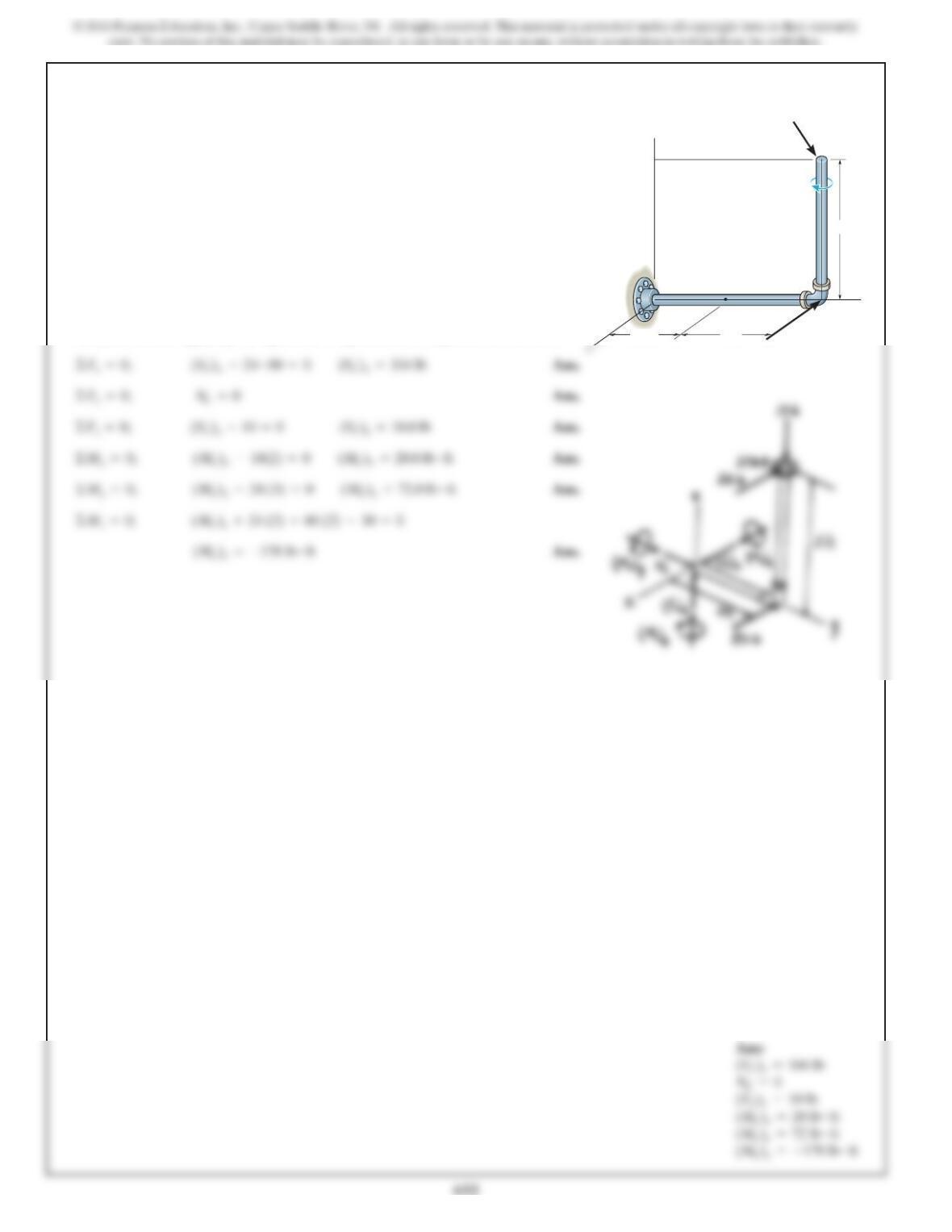
7–42.
SOLUTION
Free body Diagram: The support reactions need not be computed.
Internal Forces: Applying the equations of equilibrium to segment BC, we have
F
1
F
2
2ft
z
y
3ft
C
B
A
M
1.5 ft
Determine the x, y, z components of force and moment at
point C in the pipe assembly. Neglect the weight of the pipe.
The load acting at (0, 3.5 ft, 3 ft) is F
1
= 5–24i – 10k6 lb and
M = {–30k} lb
#
ft and at point (0, 3.5 ft, 0) F
2
= {–80i
} lb.
653
Ans:
SOLUTION
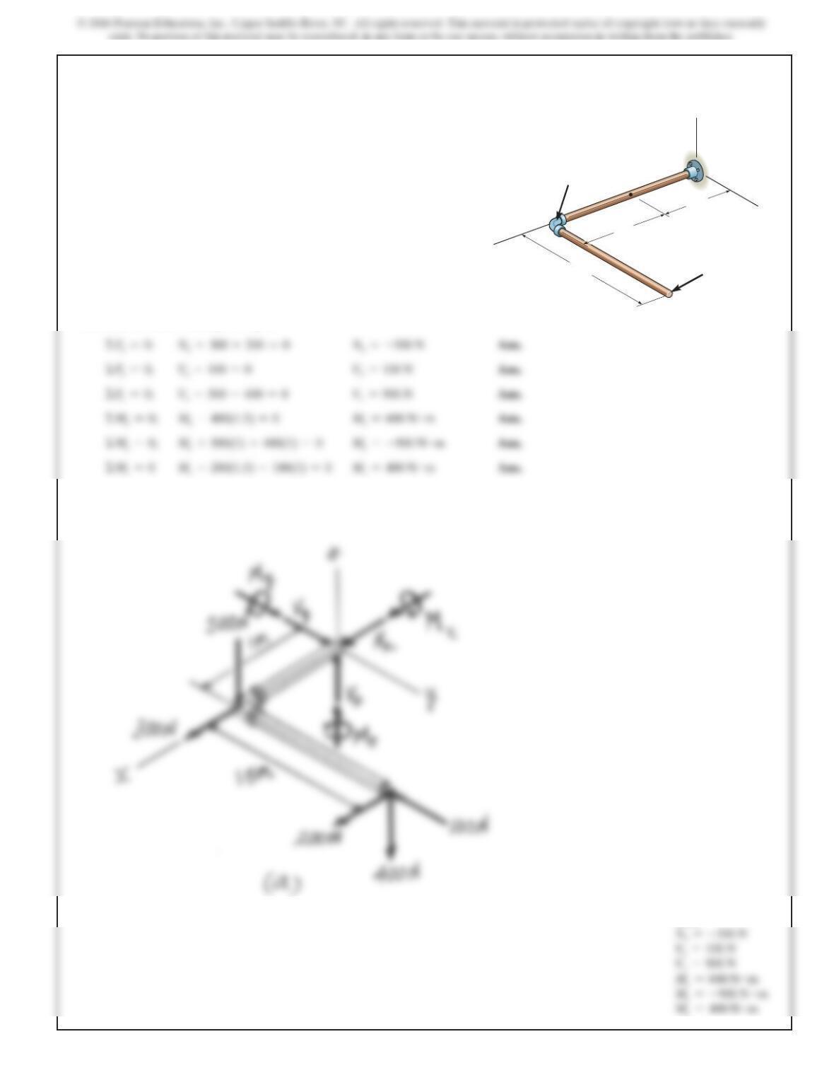
Internal Loadings. Referring to the FBD of the free end segment of the pipe
assembly sectioned through B, Fig. a,
The negative signs indicate that
Nx
and
M
y act in the opposite sense to those shown
in FBD.
7–43.
Determine the x, y, z components of internal loading at a
section passing through point B in the pipe assembly. Neglect
the weight of the pipe. Take F1 =
5
200i – 100j – 400k
6
N
and F2 =
5
300i – 500k
6
N.
x
z
y
B
A
1 m
1.5 m F1
F2
1 m
654
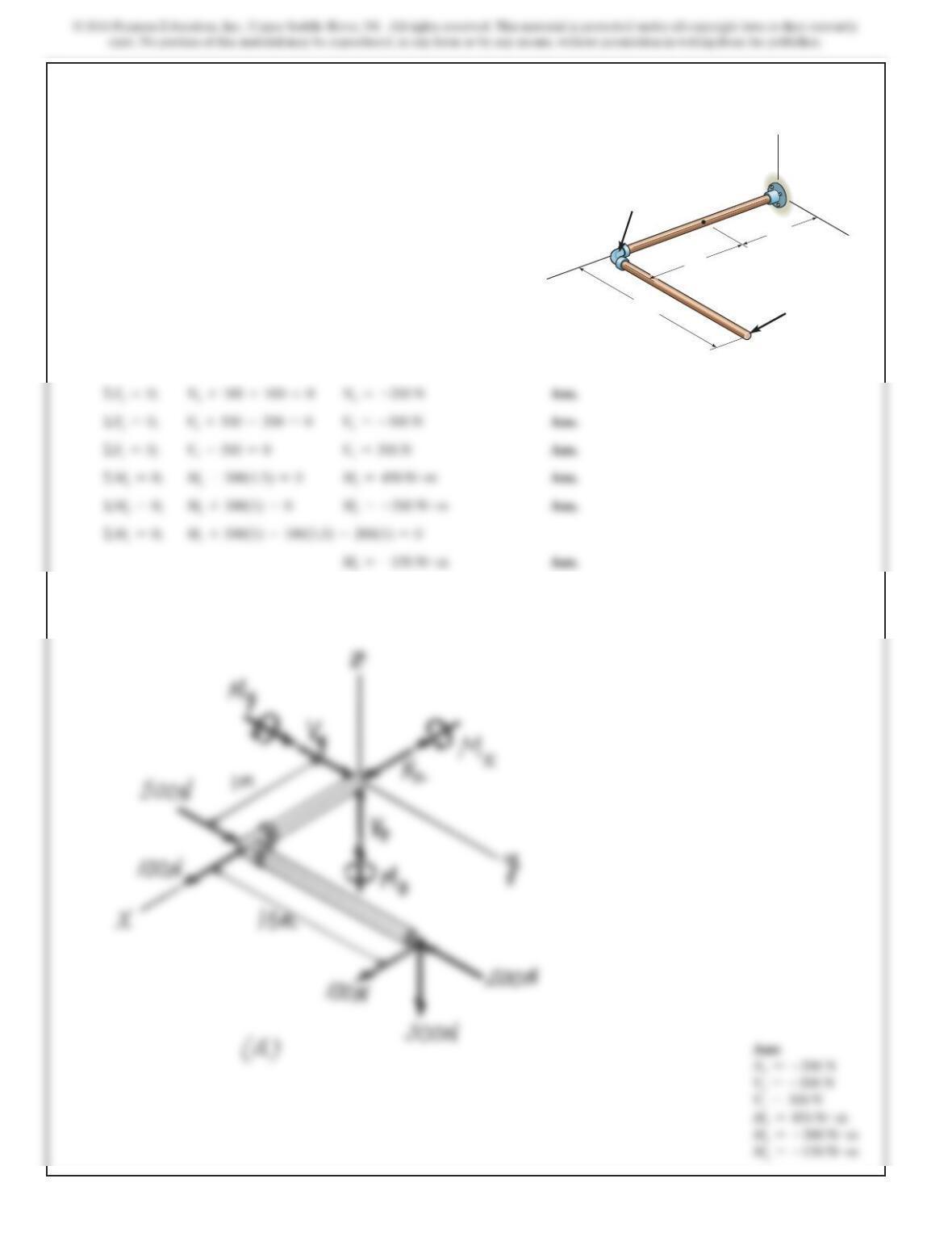
*7–44.
Determine the x, y, z components of internal loading
at a section passing through point B in the pipe
assembly. Neglect the weight of the pipe. Take
F1 =
5
100i – 200j – 300k
6
N and F2 =
5
100i + 500j
6
N.
x
z
y
B
A
1 m
1.5 m F1
F2
1 m
SOLUTION
Internal Loadings. Referring to the FBD of the free end segment of the pipe
assembly sectioned through B, Fig. a
The negative signs indicates that
Nx
,
V
y,
M
y and
Mz
act in the senses opposite to
those shown in FBD.
655
7–45.
SOLUTION
(a)
For
a6x6L
Draw the shear and moment diagrams for the shaft
(
a
)
in
terms of the parameters shown; (b) set
There is a thrust bearing at Aand a journal
bearing at B.
L=6m.
a=2m,P=9 kN,
P
a
AB
L
656
7–45. Continued
(b)
657
7–46.
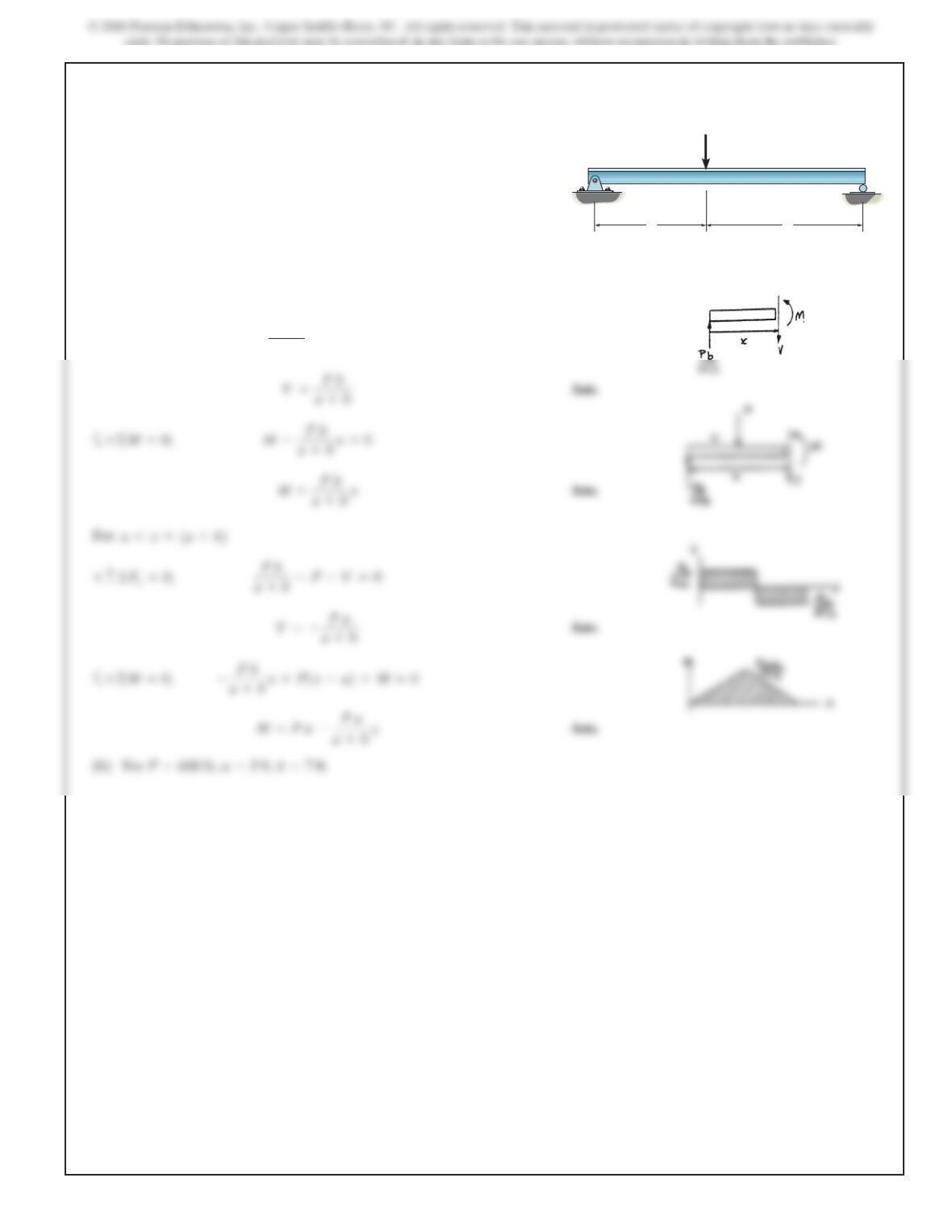
Draw the shear and moment diagrams for the beam (a) in
terms of the parameters shown; (b) set
L=12 ft.
a=5 ft,P=800 lb,
SOLUTION
aa
L
PP
658
7–46. Continued
(b) Set
For
0…x65ft
P=800 lb, a=5ft, L=12 ft
659
7–47.
SOLUTION
(a) For
Pb
a+b–V=0+c©F
y
=0;
0…x6a
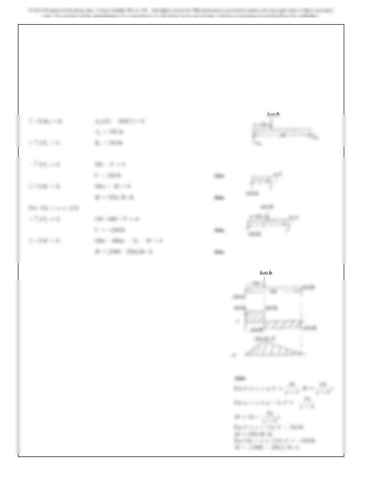
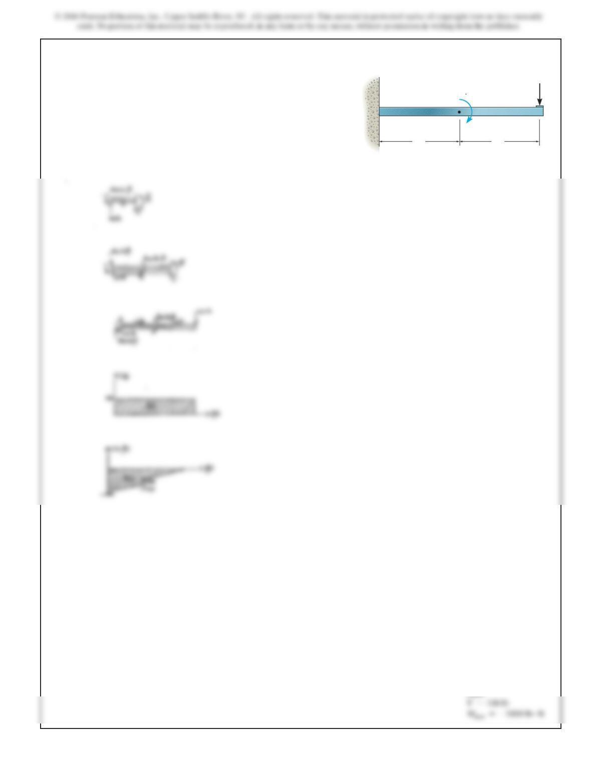
Draw the shear and moment diagrams for the beam (a) in
terms of the parameters shown; (b) set
b=7 ft.
a=5 ft,P=600 lb,
AB
P
ab
660
7–47. Continued
(b)
For
0 … x…5 ft
661
*7–48.
SOLUTION
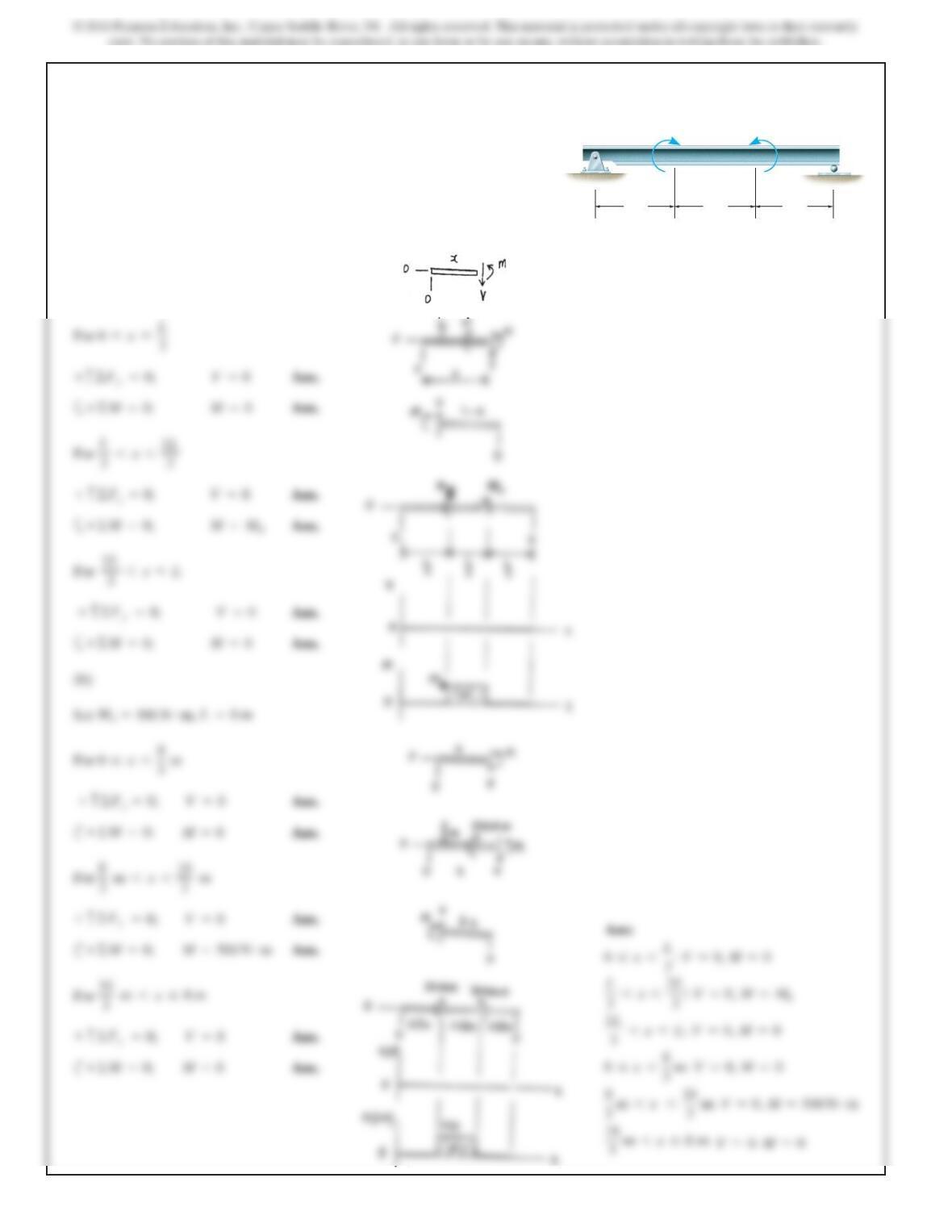
Draw the shear and moment diagrams for the cantilevered
C
B
5ft
100 lb
800 lb ft
5ft
A
beam.
Ans:
662
7–49.
SOLUTION
(a)
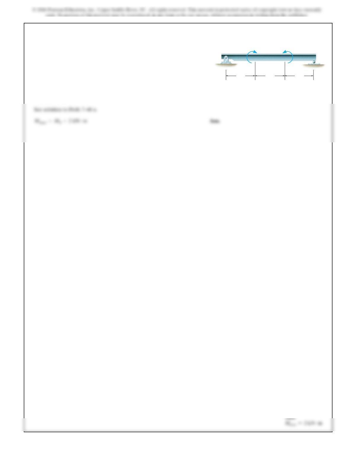
Draw the shear and moment diagrams for the beam (a) in
terms of the parameters shown; (b) set
L=8m.
M
0
=500 N
#
m,
L/3L/3L/3
M
0
M
0
663
7–50.
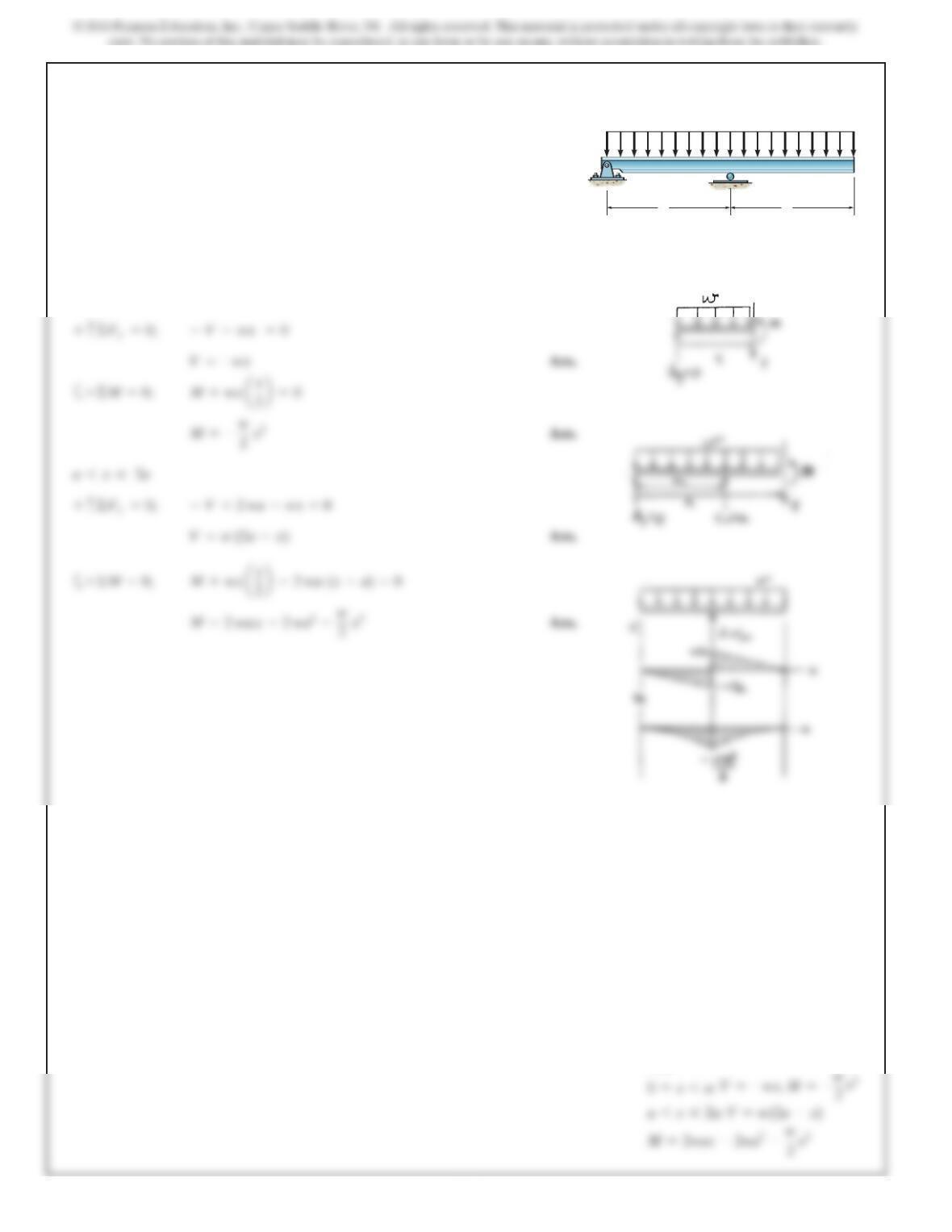
If the beam will fail when the maximum shear
force is or the maximum bending moment is
Determine the magnitude of the
largest couple moments it will support.
M
0
M
max
=2kN
#
m.
V
max
=5kN
L
=9m,
SOLUTION
L/3L/3L/3
M
0
M
0
664
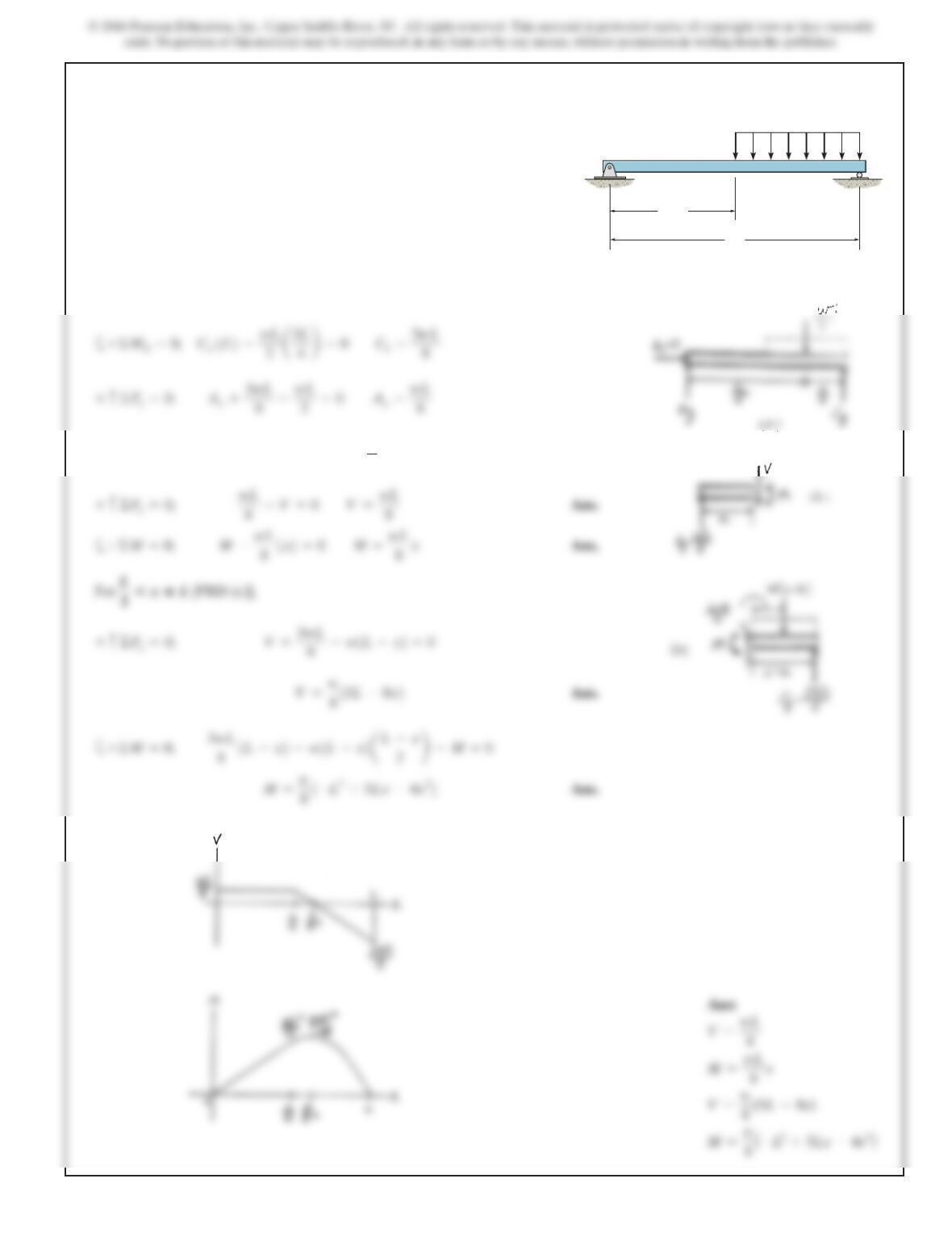
7–51.
SOLUTION
0…x6a
Draw t
h
e s
h
ear an
d
moment
di
agrams for t
h
e
b
eam.
A
BC
a a
w
Ans:
665
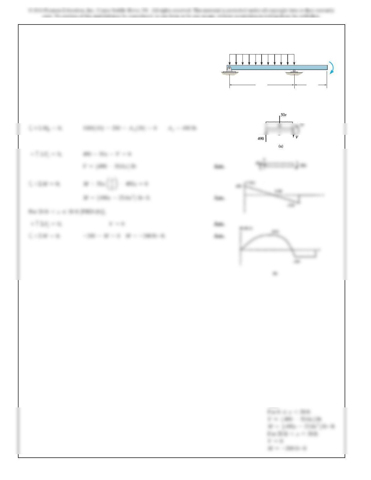
*7–52.
SOLUTION
Support Reactions: From FBD (a),
Shear and Moment Functions: For [FBD (b)],
0◊x<
L
2
Draw the shear and moment diagrams for the beam.
C
w
A
B
L
L
––
2
666
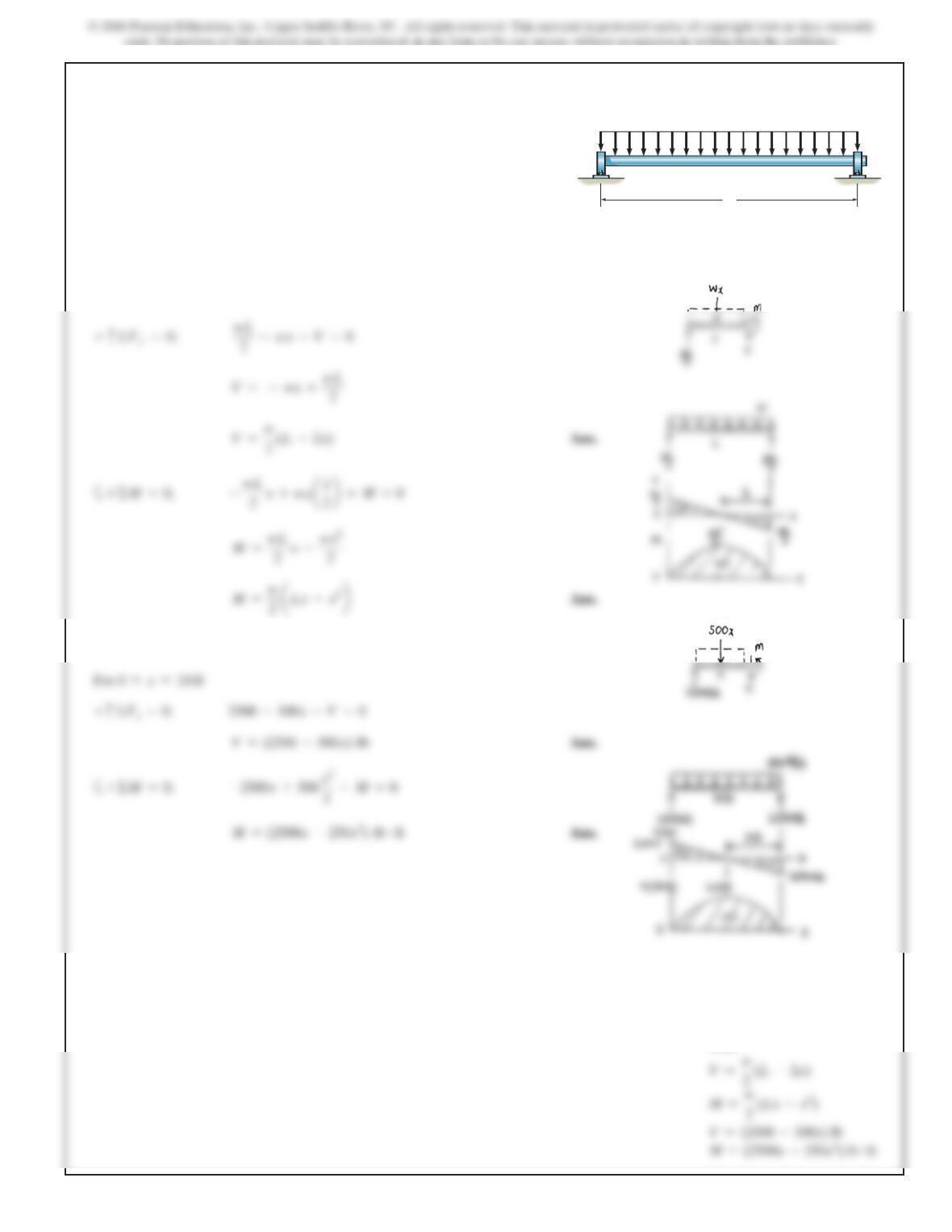
7–53.
Draw the shear and bending-moment diagrams for the beam.
SOLUTION
Support Reactions:
Shear and Moment Functions: For [FBD (a)],
0…x<20 ft
C
A
B
20 ft 10 ft
50 lb/ft
200lb·ft
Ans:
667
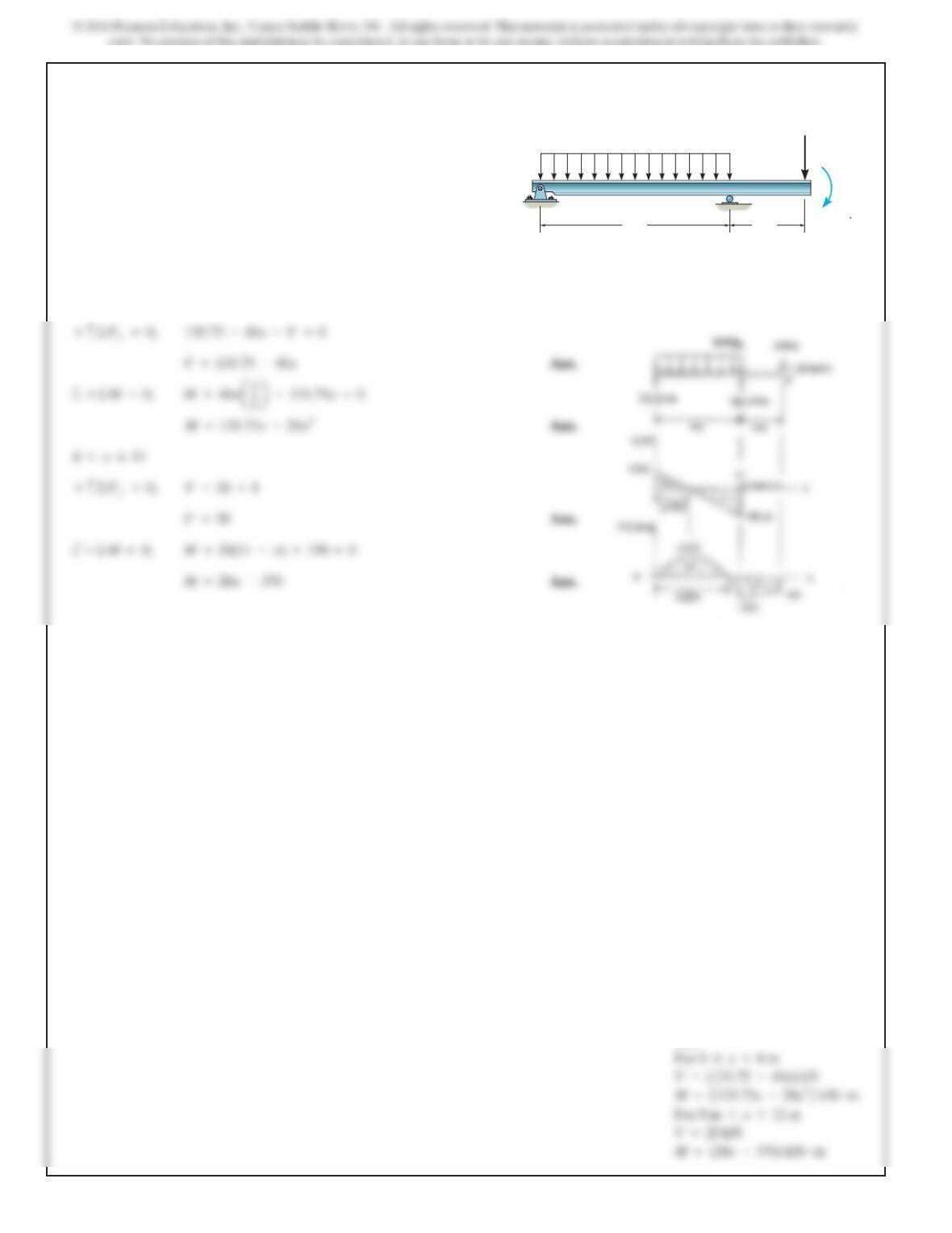
7–54.
SOLUTION
(a) For
(b) Set w= 500 lb/ft, L= 10 ft
0…x…L
Theshaft is supportedbyathrust bearing at Aand a
journal bearing at B. Draw the shear and moment diagrams
for the shaft (a) in terms of the parameters shown; (b) set
L=10 ft.w=500 lb>ft,
L
AB
w
Ans:
668
7–55.
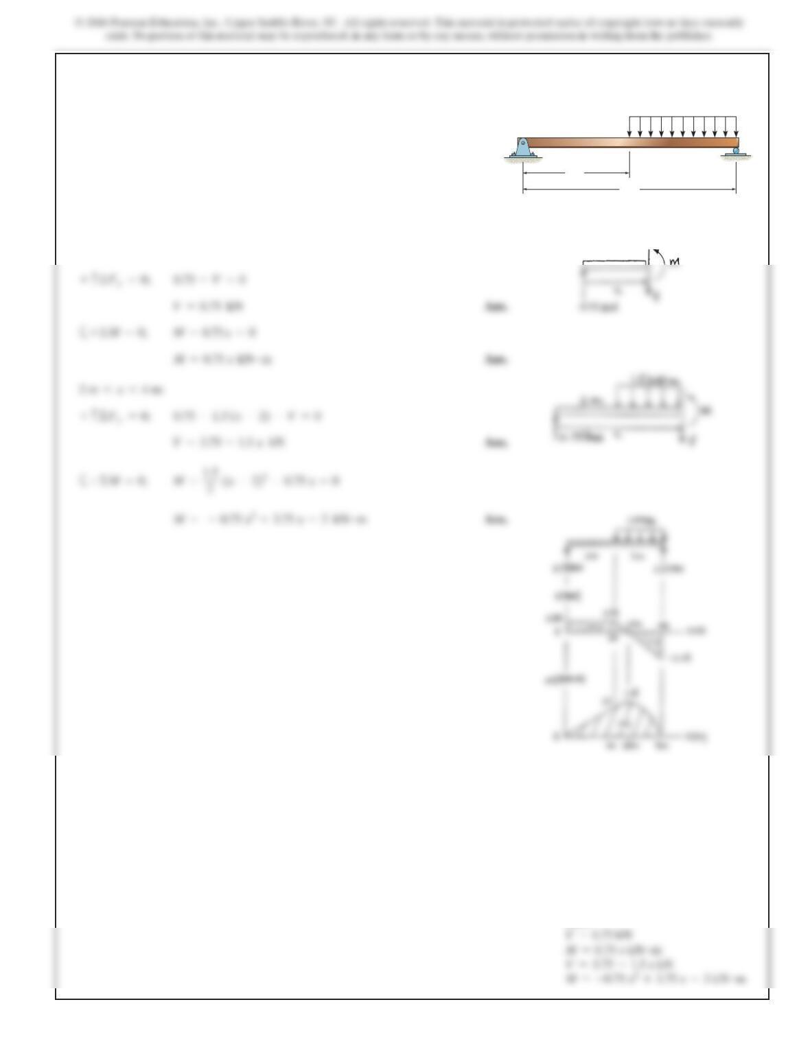
Draw t
h
es
h
ear an
d
moment
di
agrams for t
h
e
b
eam.
SOLUTION
0…x68
40 kN/m
20 kN
150 kN m
A
BC
8m 3m
Ans:
669
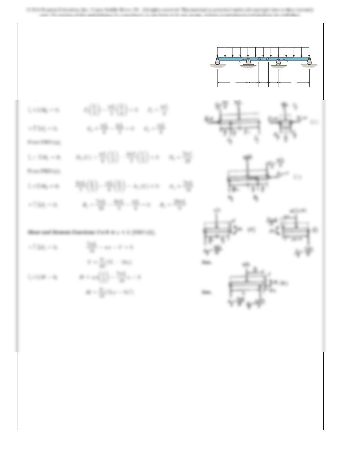
*7–56.
SOLUTION
:
0…x…2m
Draw the shear and moment diagrams for the beam.
2m
4m
1.5 kN/m
ABC
Ans:
670
7–57.
Draw the shear and moment diagrams for the compound
beam. The beam is pin-connected at Eand F.
A
L
w
BEFC
D
L
––
3
L
––
3
L
––
3
L
SOLUTION
Support Reactions: From FBD (b),