328
Ans:
SOLUTION
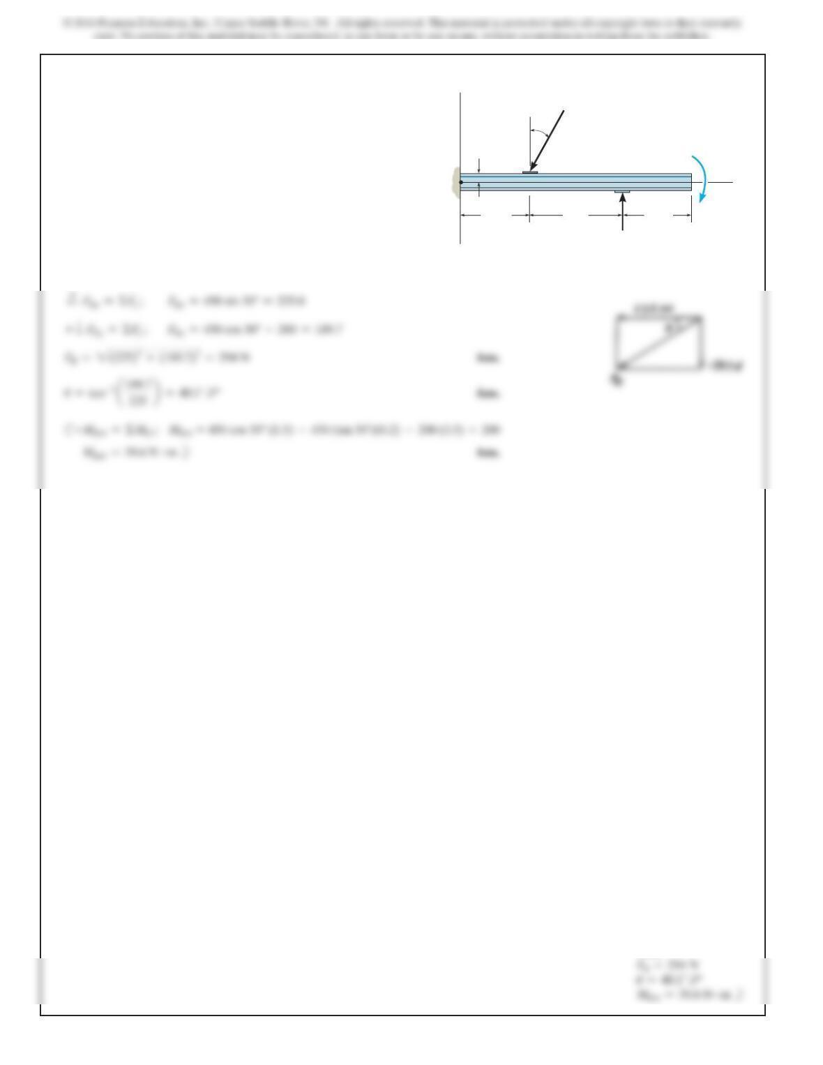
4–101.
Replace the loading system acting on the beam by an
equivalent resultant force and couple moment at point O.30
y
x
450 N
O
200 N
0.2 m 200 N m
2 m
1.5 m 1.5 m
329
SOLUTION
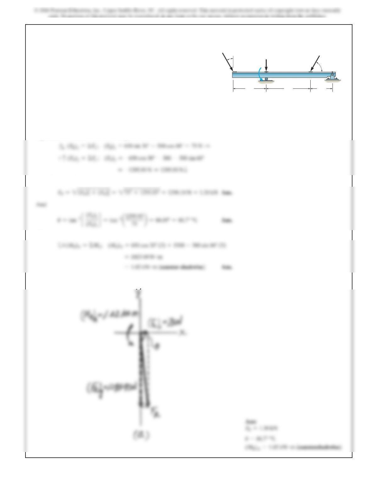
Equivalent Resultant Force And Couple Moment at Point A.
As indicated in Fig. a,
Also,
4–102.
Replace the loading system acting on the post by an
equivalent resultant force and couple moment at point A.
3 m
500 N
30
60
1500 N m
5 m 2 m
650 N
300 N
B
A
330
SOLUTION
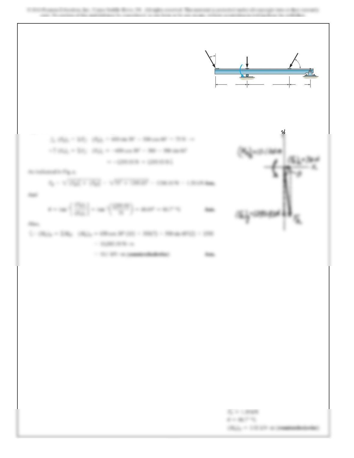
Equivalent Resultant Force And Couple Moment At Point B.
4–103.
Replace the loading system acting on the post by an
equivalent resultant force and couple moment at point B.
3 m
500 N
30
60
1500 N m
5 m 2 m
650 N
300 N
B
A
Ans:
331
Ans:
R
A=
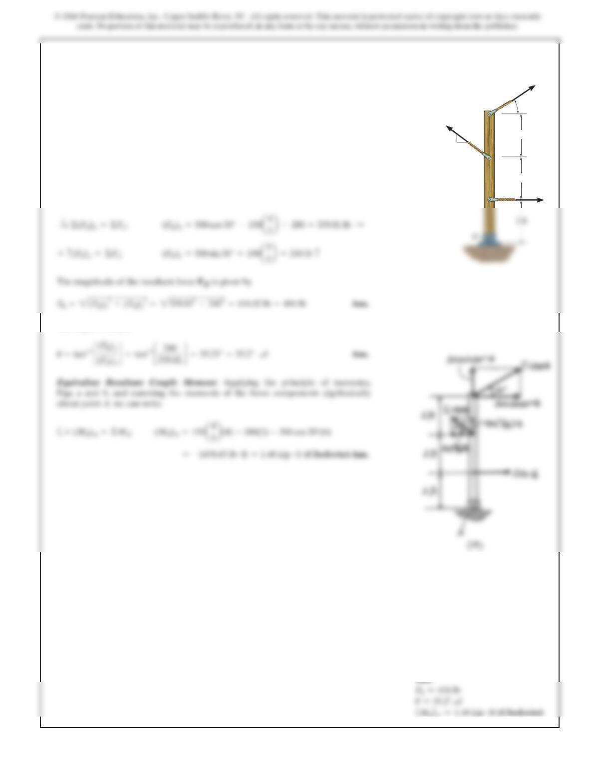
*4–104.
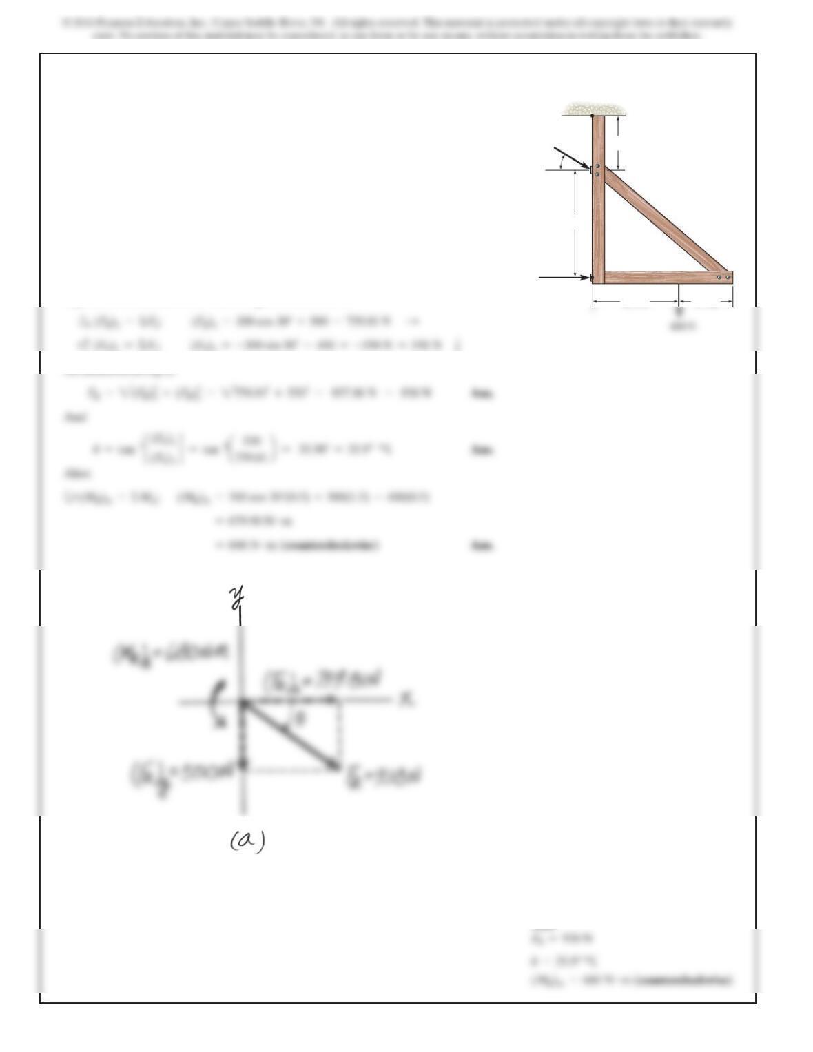
Replace the force system acting on the post by a resultant
force and couple moment at point O.
SOLUTION
Equivalent Resultant Force:Forces F1and F2are resolved into their xand ycom-
ponents,Fig.a.Summing these force components algebraically along the xand y
axes, we have
The angle of is
FR
u
150 lb
300 lb
200 lb
3
4
5
2 ft
2 ft
30
332
SOLUTION
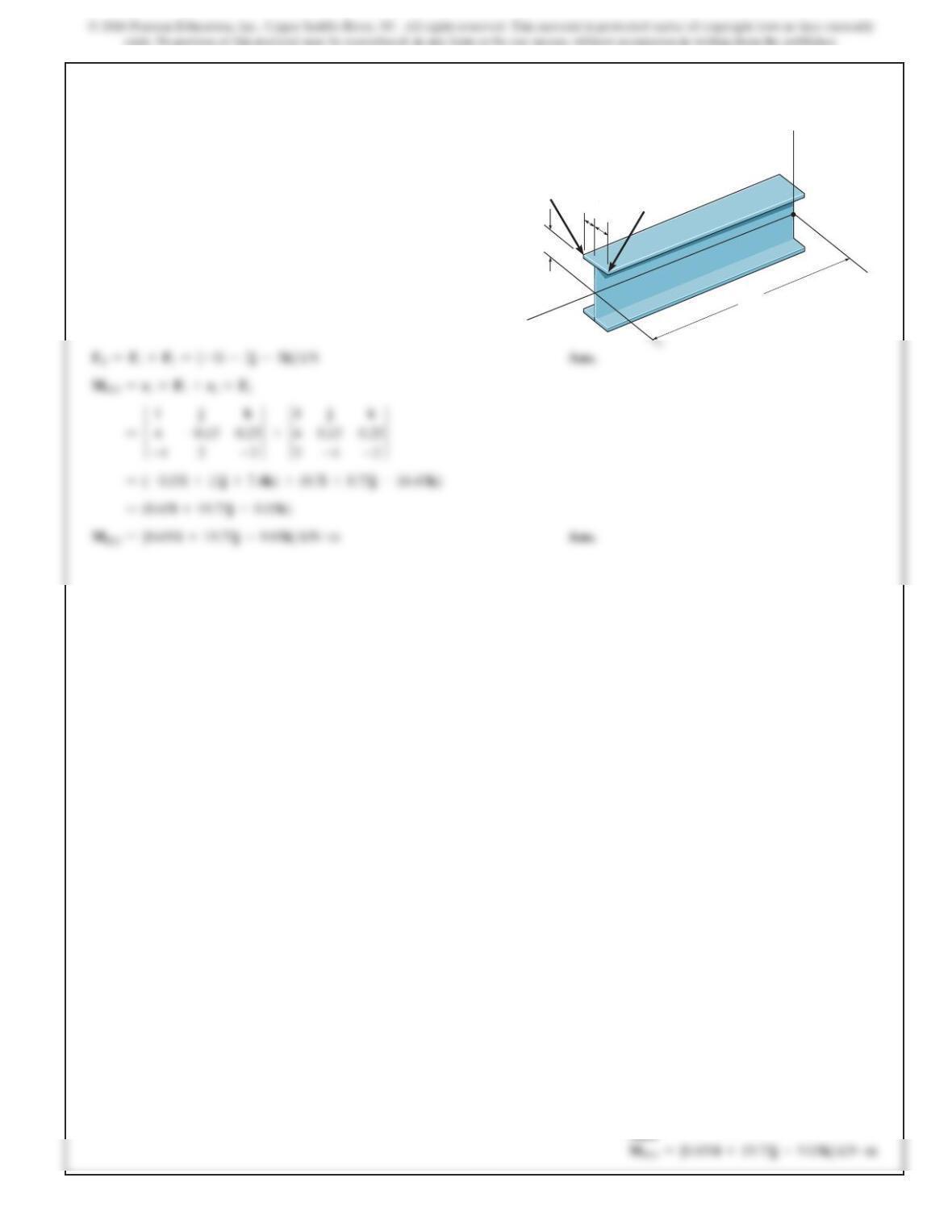
Equivalent Resultant Force And Couple Moment At A.
As indicated in Fig. a,
4–105.
Replace the force system acting on the frame by an
equivalent resultant force and couple moment acting at
point A.
1 m
0.5 m 0.3 m
0.5 m
500 N
300 N
A
30
Ans:
333
SOLUTION
4–106.
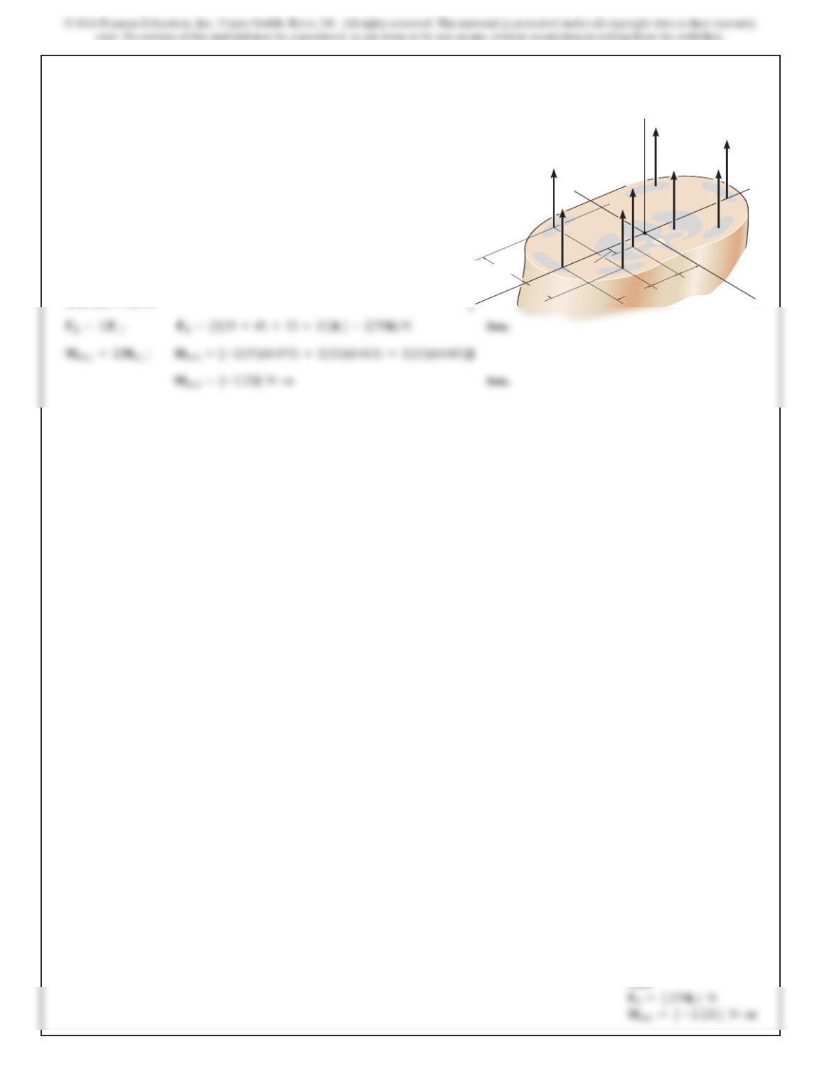
The forces
F1={–4i+2j–3k} kN
and F2
={3i–4j–
2k} kN
act on the end of the beam. Replace these forces by
an equivalent force and couple moment acting at point O.
Ans:
y
z
x
F1150 mm
150 mm F2
250 mm
O
4 m
334
Ans:
4–107.
A
bi
omec
h
an
i
ca
l
mo
d
e
l
of t
h
e
l
um
b
ar reg
i
on of t
h
e
h
uman
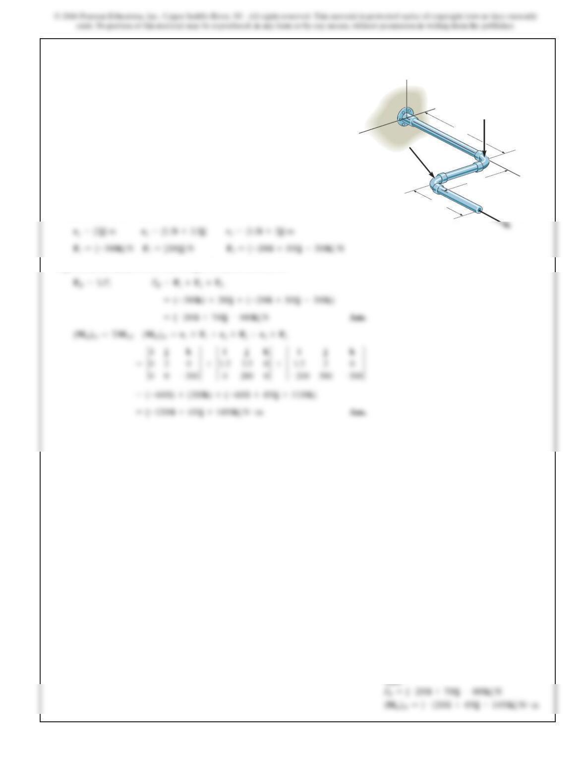
trunk is shown. The forces acting in the four muscle groups
consist of for the rectus,for the
oblique,for the lumbar latissimus dorsi, and
for the erector spinae.These loadings are
symmetric with respect to the y–z plane.Replace this system
of parallel forces by an equivalent force and couple moment
acting at the spine, point O. Express the results in Cartesian
vector form.
F
E=32 N
F
L=23 N
F
O=45 NF
R=35 N
SOLUTION
75 mm
45 mm 50 mm 40 mm
30 mm
15 mm
z
y
F
R
F
O
F
L
F
E
F
R
F
E
F
L
F
O
O
335
SOLUTION
Position And Force Vectors.
F3={–200i+500j–300k} N
Equivalent Resultant Force And Couple Moment At Point O.
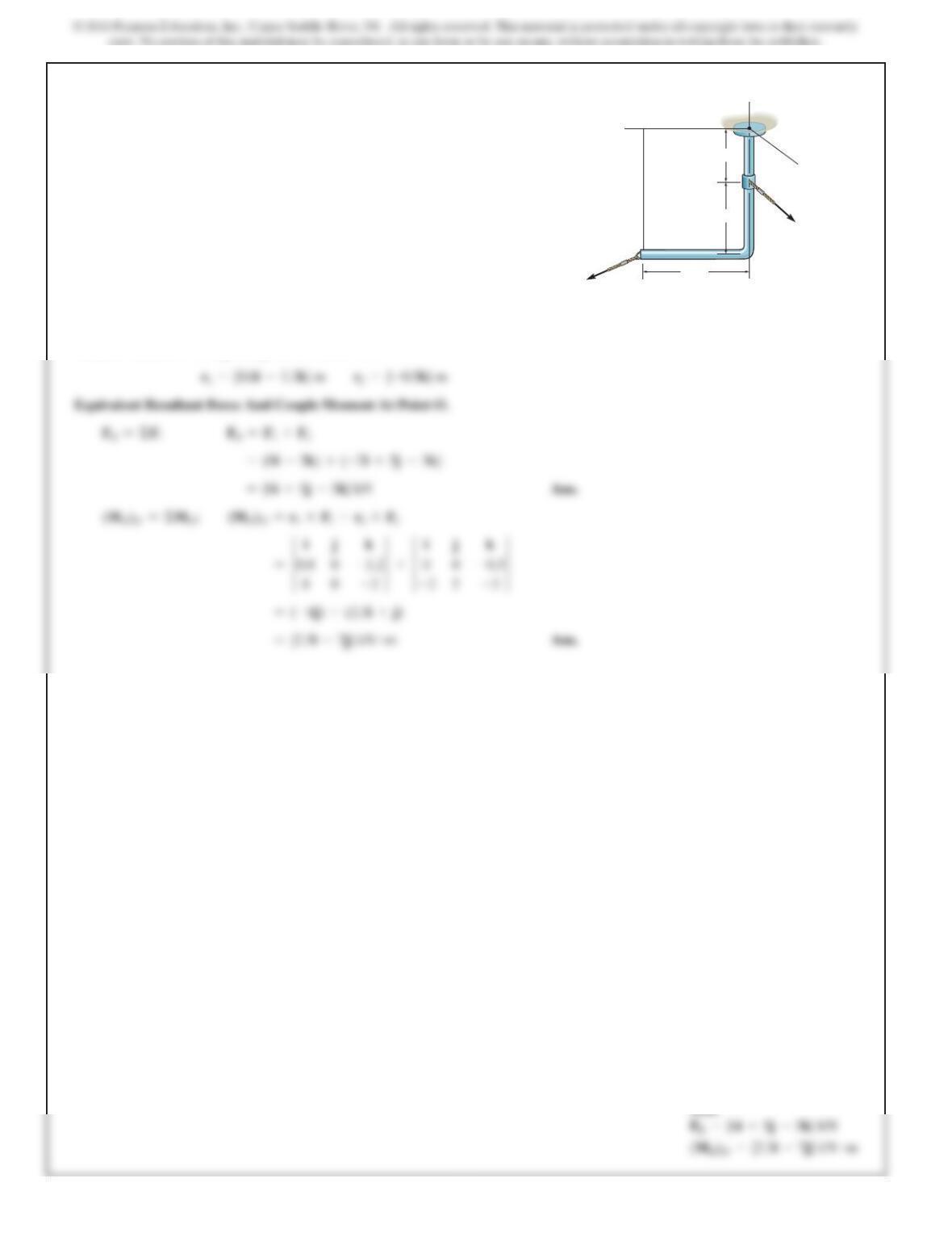
*4–108.
Replace the force system by an equivalent resultant
force and couple moment at point O. Take
F3={–200i+500j–300k} N.
y
O
z
x2 m
F2 = 200 N
F1 = 300 N
1.5 m
1.5 m
F3
336
Ans:
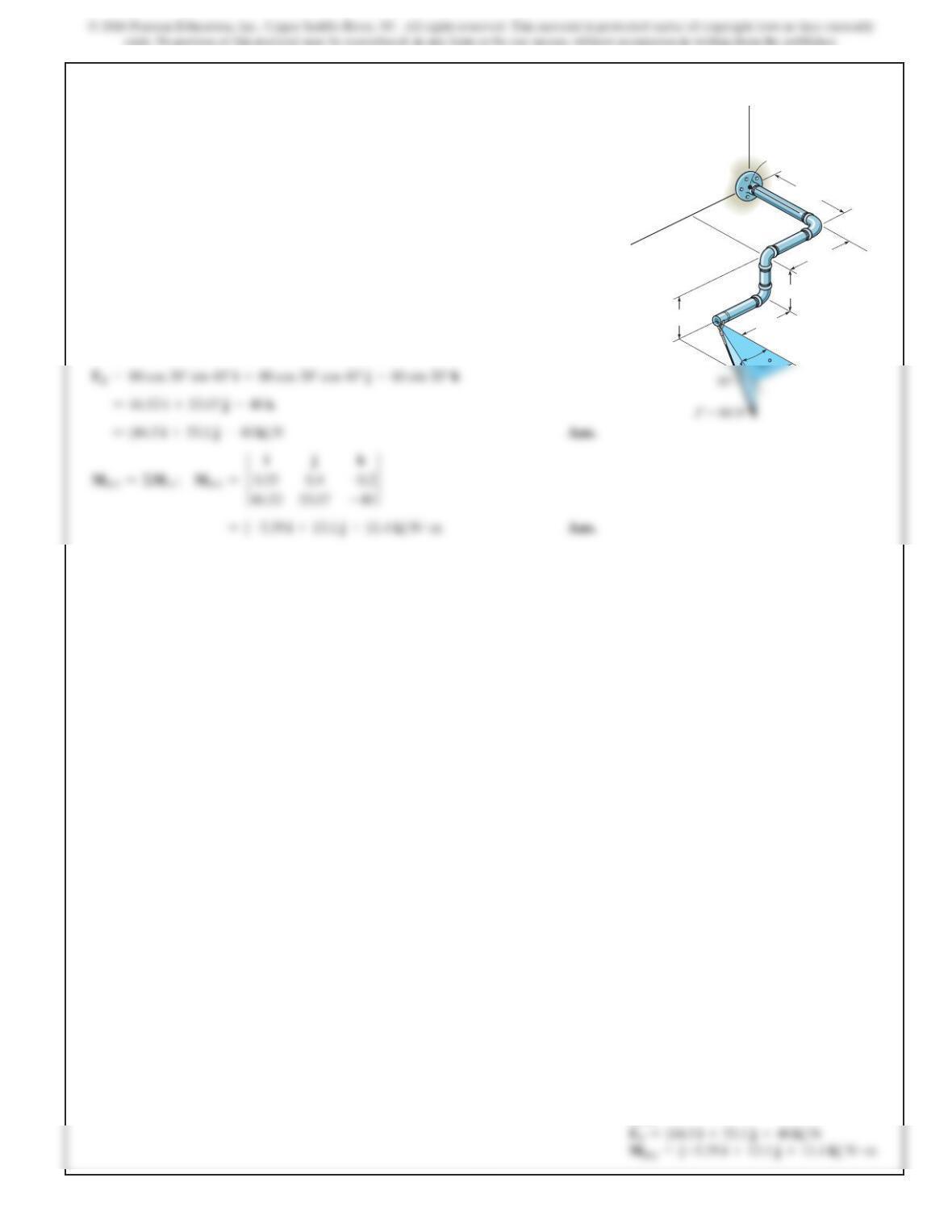
4–109.
Replace the loading by an equivalent resultant force and
couple moment at point O.
SOLUTION
Position Vectors. The required position vectors are
0.8 m
0.5 m
0.7 m
x
y
O
z
F = {–2 i + 5 j – 3 k} kN
F {8 i – 2 k} kN
1
2
337
Ans:
SOLUTION
FR=ΣF ;
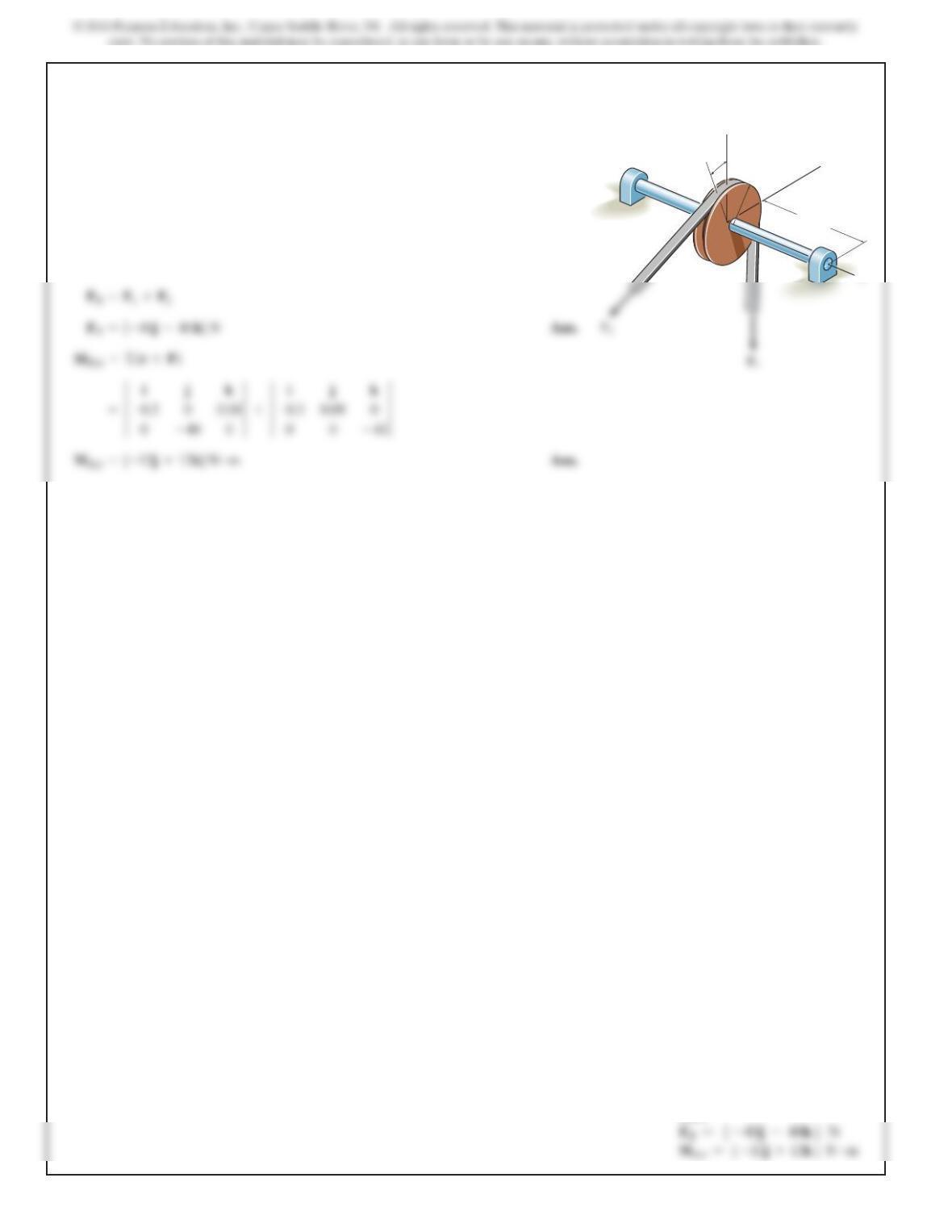
4–110.
Replace the force of F
=
80 N acting on the pipe assembly
by an equivalent resultant force and couple moment at
point A.
[
400 mm
y
300 mm
200 mm
250 mm
200 mm
B
A
z
338
Ans:
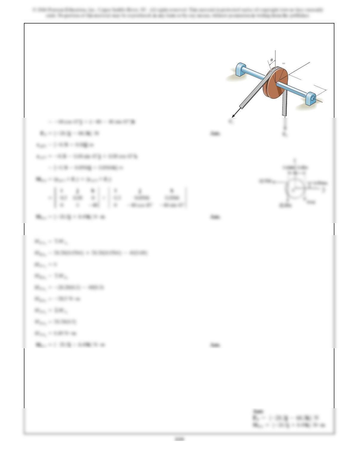
4–111.
T
h
e
b
e
l
tpass
i
ng over t
h
epu
ll
ey
i
ssu
bj
ecte
d
to forces an
d
each having amagnitude of 40 N. acts in the direction.
Replace these forces by an equivalent force and couple
moment at point A.Express the result in Cartesian vector form.
Set so that acts in the direction.–jF2
u=0°
–kF1
F2,
F
1
SOLUTION
x
y
z
300 mm
r80 mm
A
*4–112.
T
h
e
b
e
l
t pass
i
ng over t
h
e pu
ll
ey
i
s su
bj
ecte
d
to two forces
and each having a magnitude of 40 N. acts in the
direction. Replace these forces by an equivalent force and
couple moment at point A. Express the result in Cartesian
vector form. Take u=45°.
–k
F1
F2,
F
1
SOLUTION
Also,
FR=F1+F2
x
y
z
300 mm
r80 mm
A
340
Ans:
4–113.
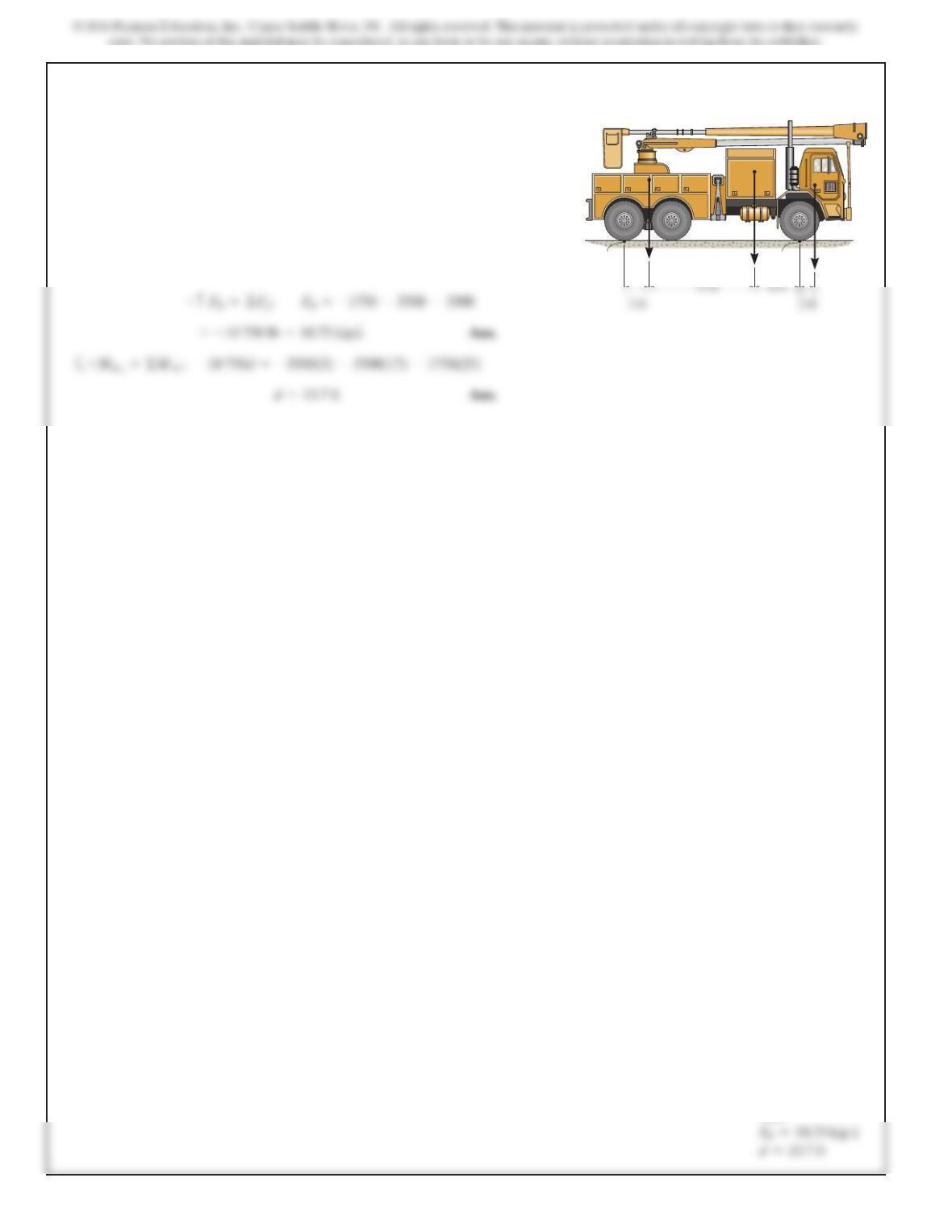
The weights of the various components of the truck are
shown. Replace this system of forces by an equivalent
resultant force and specify its location measured from B.
SOLUTION
AB 3500 lb 5500 lb 1750 lb
341
4–114.
SOLUTION
Equivalent Force:
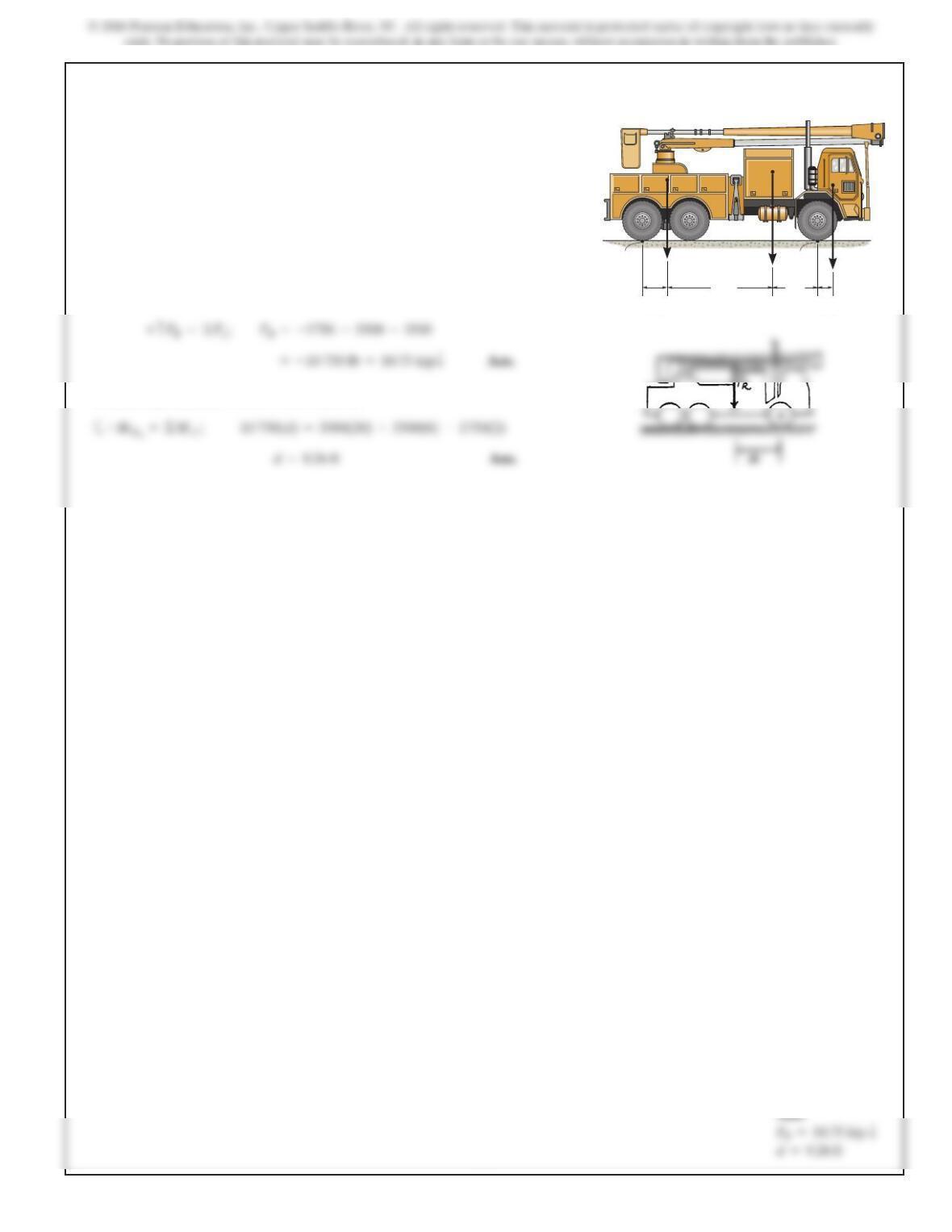
Location of Resultant Force From Point A:
The weights of the various components of the truck are
shown. Replace this system of forces by an equivalent
resultant force and specify its location measured from
point A.
14 ft 6 ft
2ft3ft
AB 3500 lb 5500 lb 1750 lb
342
Ans:
4–115.
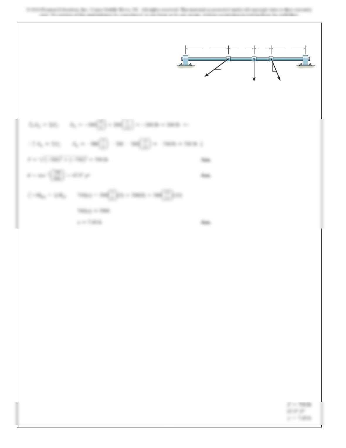
Replace the three forces acting on the shaft by a single
resultant force. Specify where the force acts, measured from
end A.
SOLUTION
5 ft 3 ft 2 ft 4 ft
200 lb
3
4
5
500 lb
260 lb
5
12 13
BA
343
Ans:
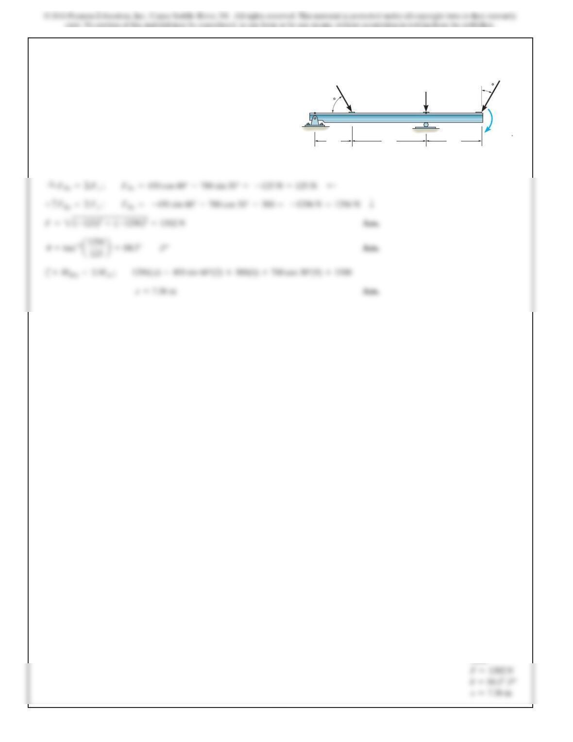
*4–116.
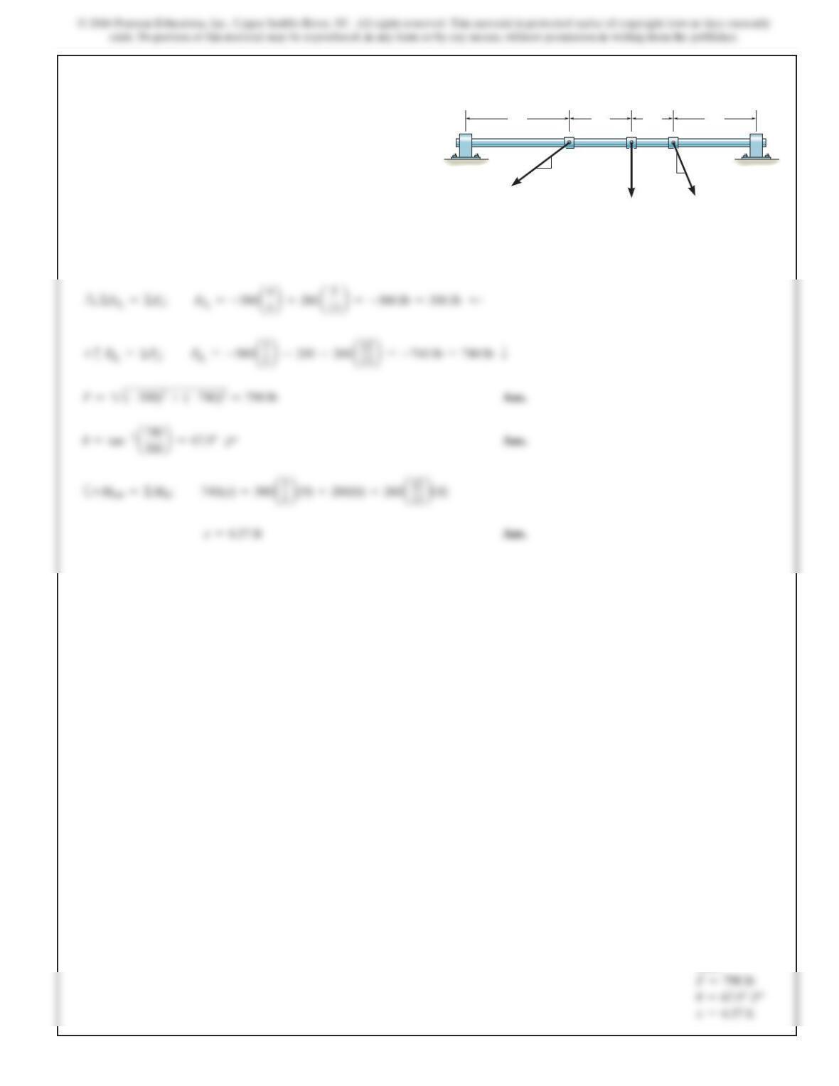
Replace the three forces acting on the shaft by a single
resultant force. Specify where the force acts, measured from
end B.
SOLUTION
5 ft 3 ft 2 ft 4 ft
200 lb
3
4
5
500 lb
260 lb
5
12 13
BA
344
Ans:
4–117.
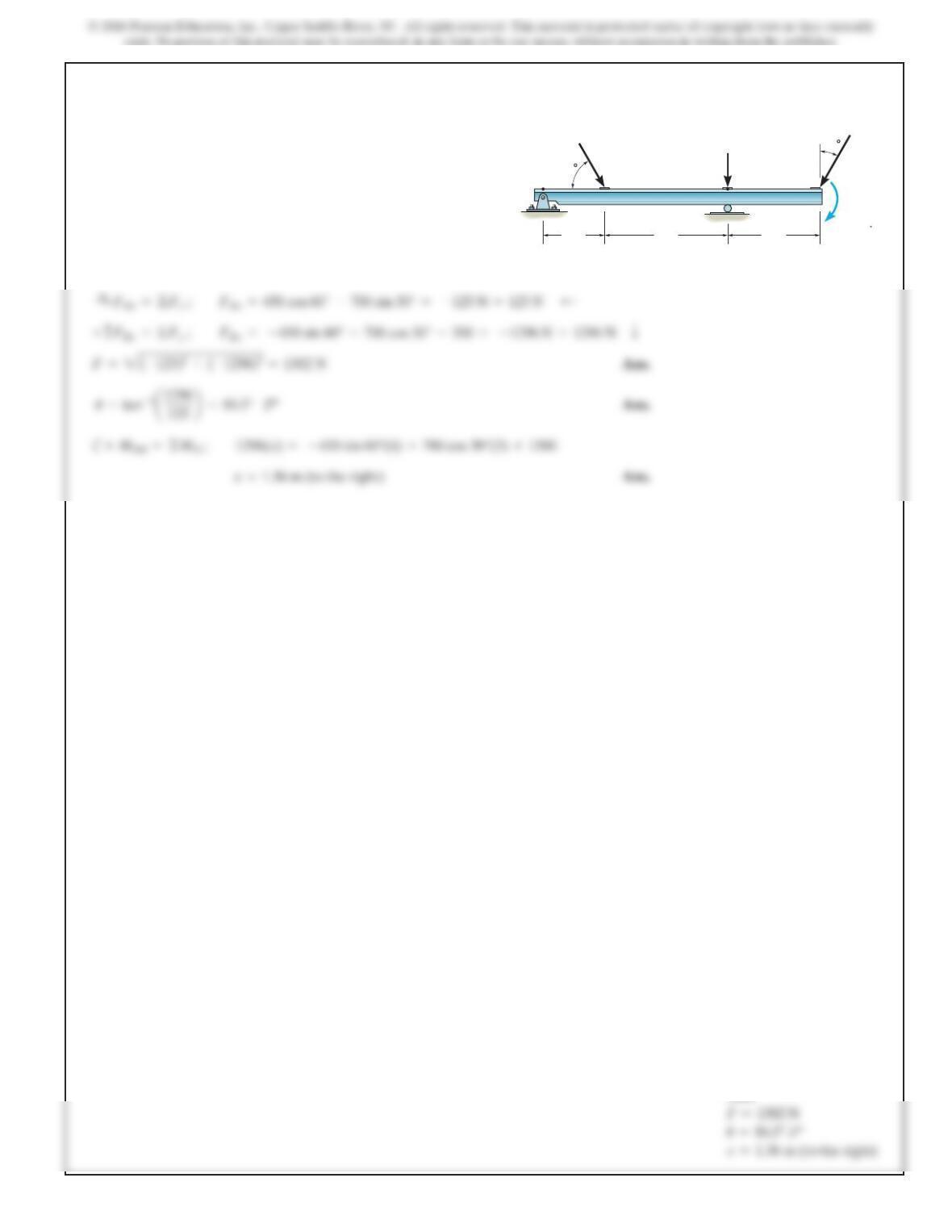
Replace the loading acting on the beam byasingle resultant
force.Specify where the force acts,measured from end A.
SOLUTION
2 m
300 N 30
60
1500 Nm
4 m 3 m
450 N
700 N
A
B
345
Ans:
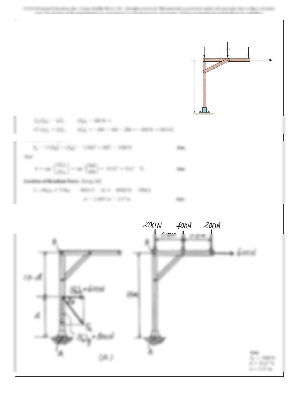
4–118.
Rep
l
ace t
h
e
l
oa
di
ng act
i
ng on t
h
e
b
eam
b
yas
i
ng
l
eresu
l
tant
force.Specify where the force acts,measured from B.
SOLUTION
2 m
300 N 30
60
1500 N m
4 m 3 m
450 N
700 N
A
B
346
SOLUTION
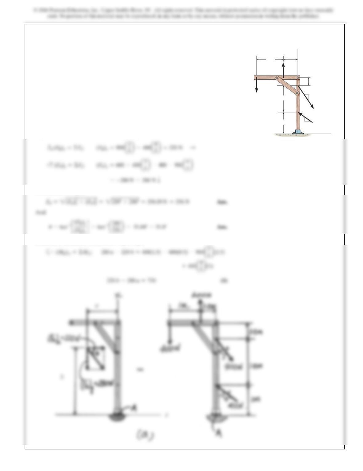
Equivalent Resultant Force. Referring to Fig. a,
As indicated in Fig. a,
4–119.
Replace the loading on the frame by a single resultant force.
Specify where its line of action intersects a vertical line
along member AB, measured from A.
1.5 m
0.5 m 0.5 m
200 N200 N
400 N
600 N
A
B
C
347
*4–120.
Replace the loading on the frame by a single resultant force.
Specify where its line of action intersects a vertical line
along member AB, measured from A.
1 m
B
A
y
0.5 m
1 m
0.5 m
400 N
600 N
54
3
400 N
900 N
1.5 m
x
5
4
3
SOLUTION
Equivalent Resultant Force. Referring to Fig. a
As indicated in Fig. a,
Location of Resultant Force. Referring to Fig. a