2–1.
SOLUTION
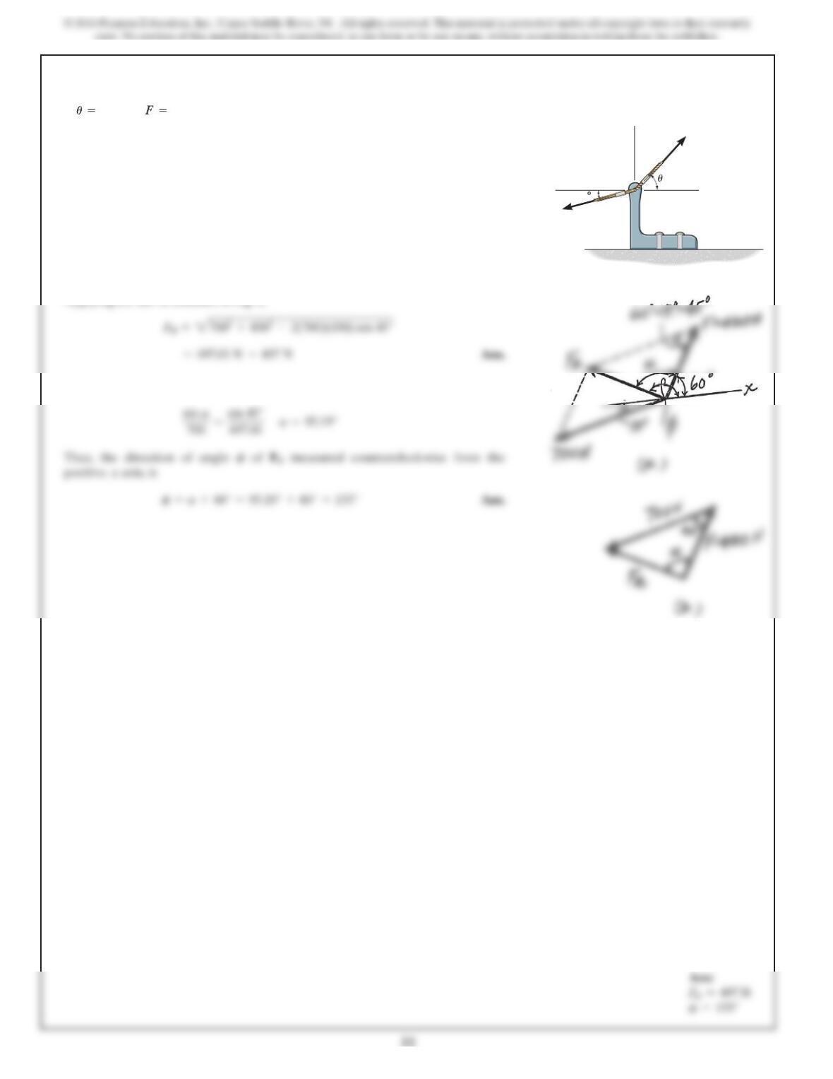
The parallelogram law of addition and the triangular rule are shown in Figs. aand b,
respectively.
Applying the law of consines to Fig. b,
This yields
If and ,determine the magnitude of the
resultant force and its direction, measured counterclockwise
from the positive xaxis.
4
5
0 N60°
x
y
700 N
F
15
2 3
2–2.
SOLUTION
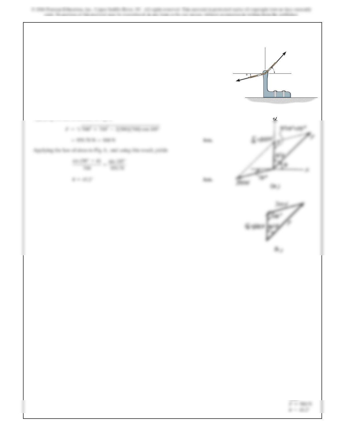
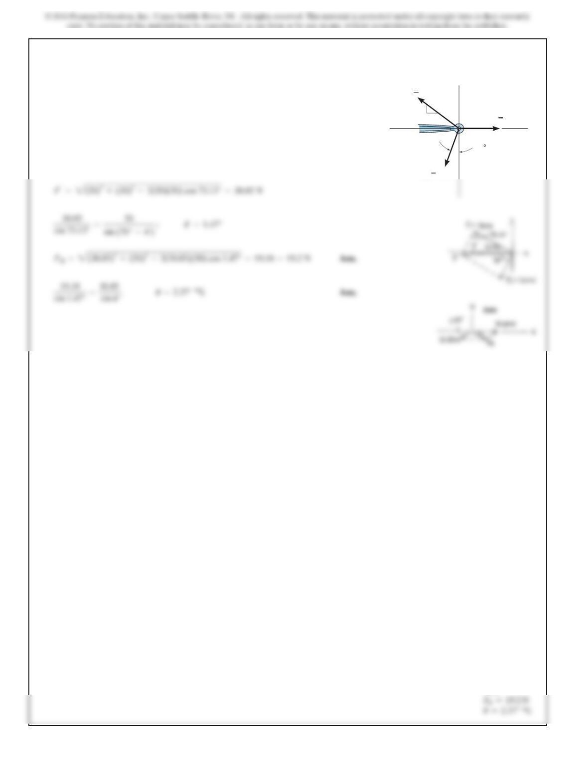
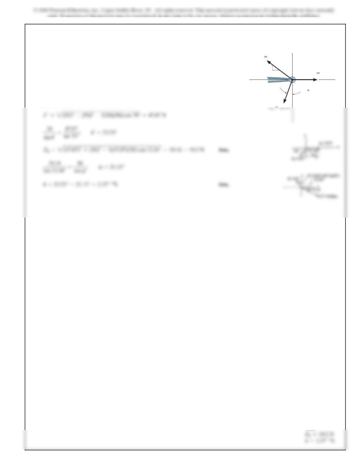
The parallelogram law of addition and the triangular rule are shown in Figs. aand b,
respectively.
Applying the law of cosines to Fig. b,
If the magnitude of the resultant force is to be 500 N,
directed along the positive yaxis, determine the magnitude
of force Fand its direction .u
x
y
700 N
F
u
15
Ans:
2 4
2–3.
SOLUTION
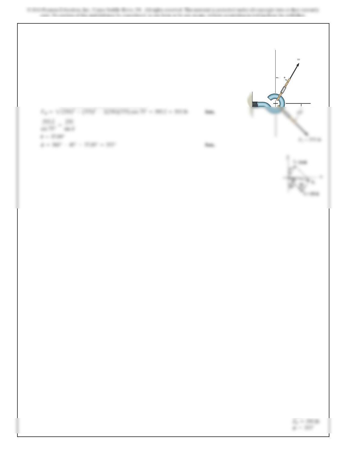
Determine the magnitude of the resultant force
and its direction, measured counterclockwise from the positive
xaxis.
F
R
=F
1
+F
2
y
x
F
1
250 lb
30
Ans:
2 5
*2–4.
SOLUTION
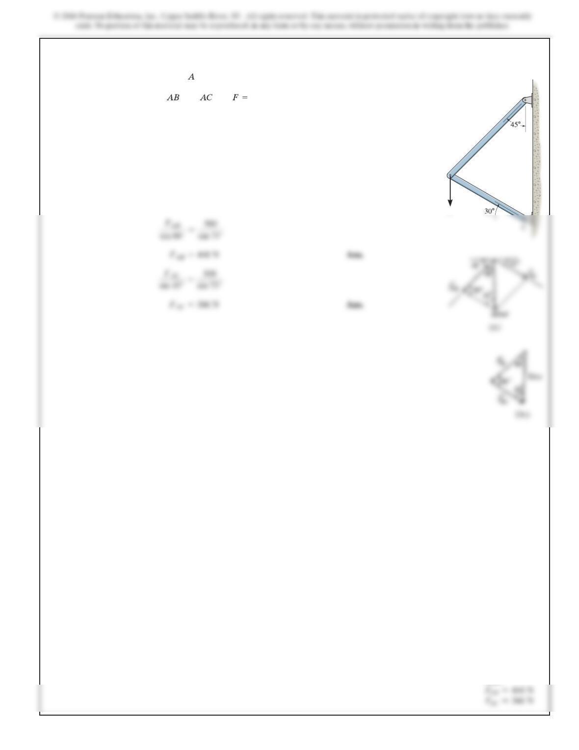
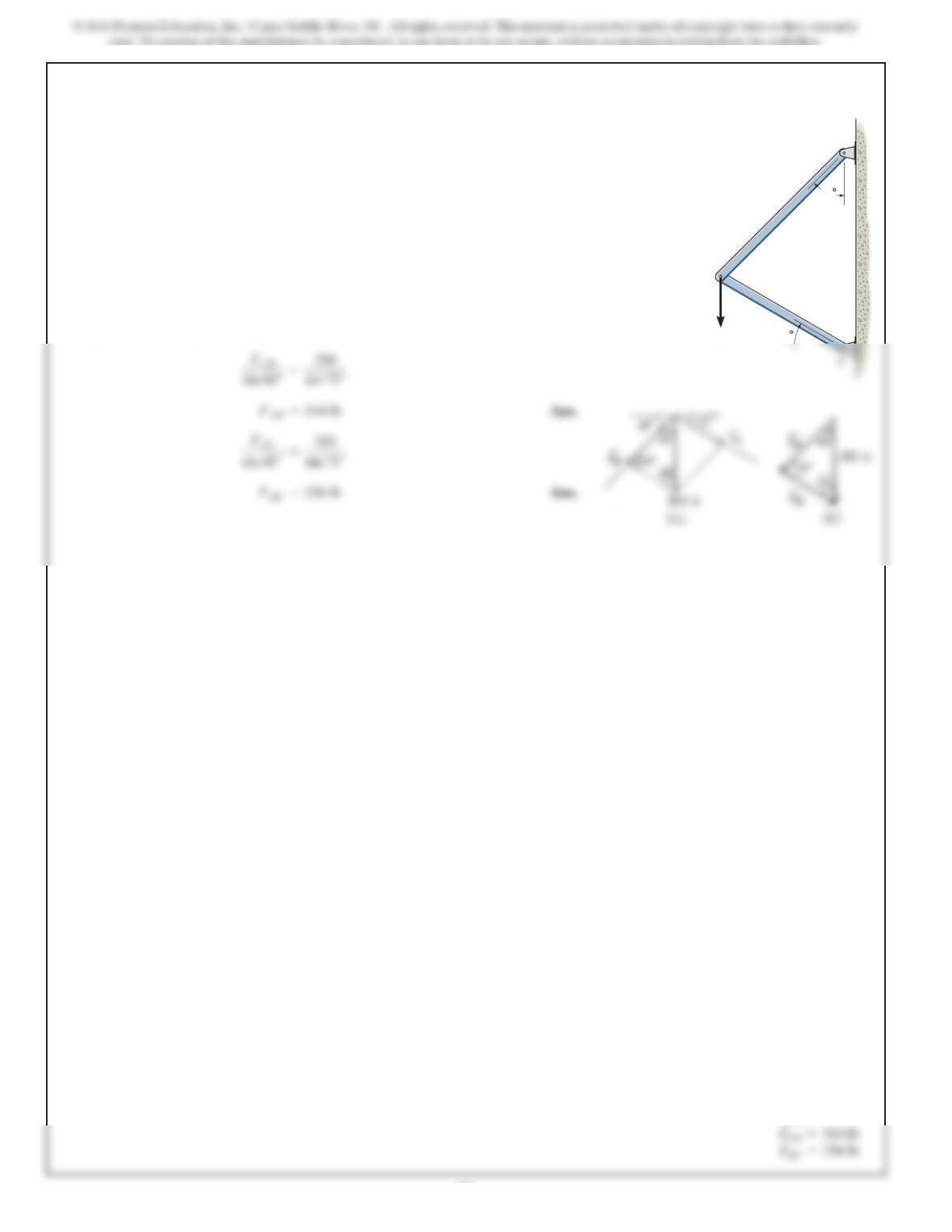
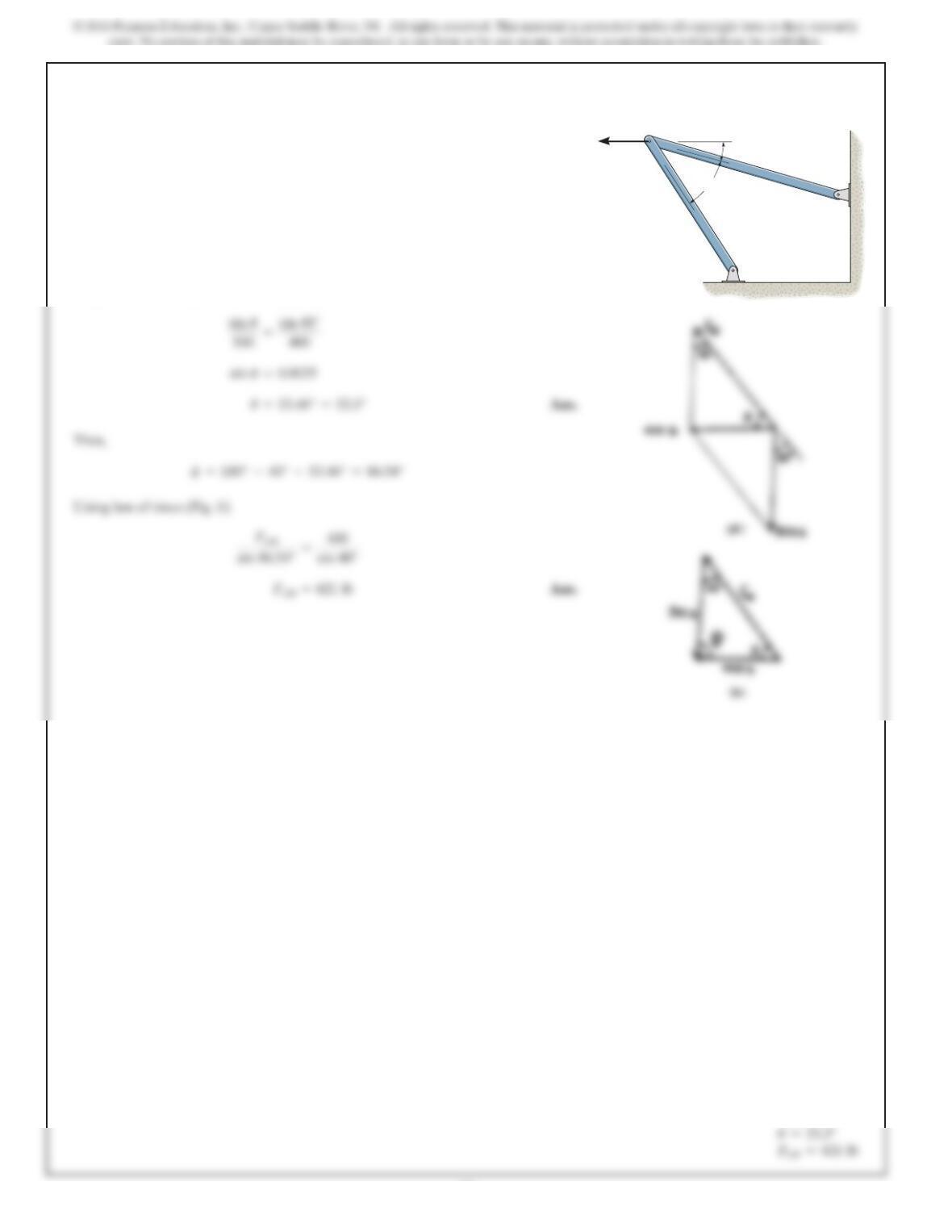
Parallelogram Law: The parallelogram law of addition is shown in Fig. a.
Trigonometry: Using the law of sines (Fig.b), we have
The vertical force acts downward at on the two-membered
frame. Determine the magnitudes of the two components of
directed along the axes of and . Set .
500 NF
F
F
B
A
Ans:
2 6
2–5.
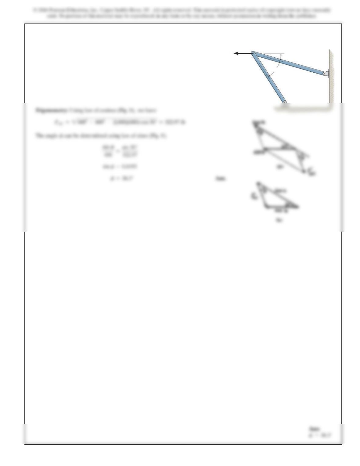
Solve Prob. 2-4 with .F=350 lb
SOLUTION
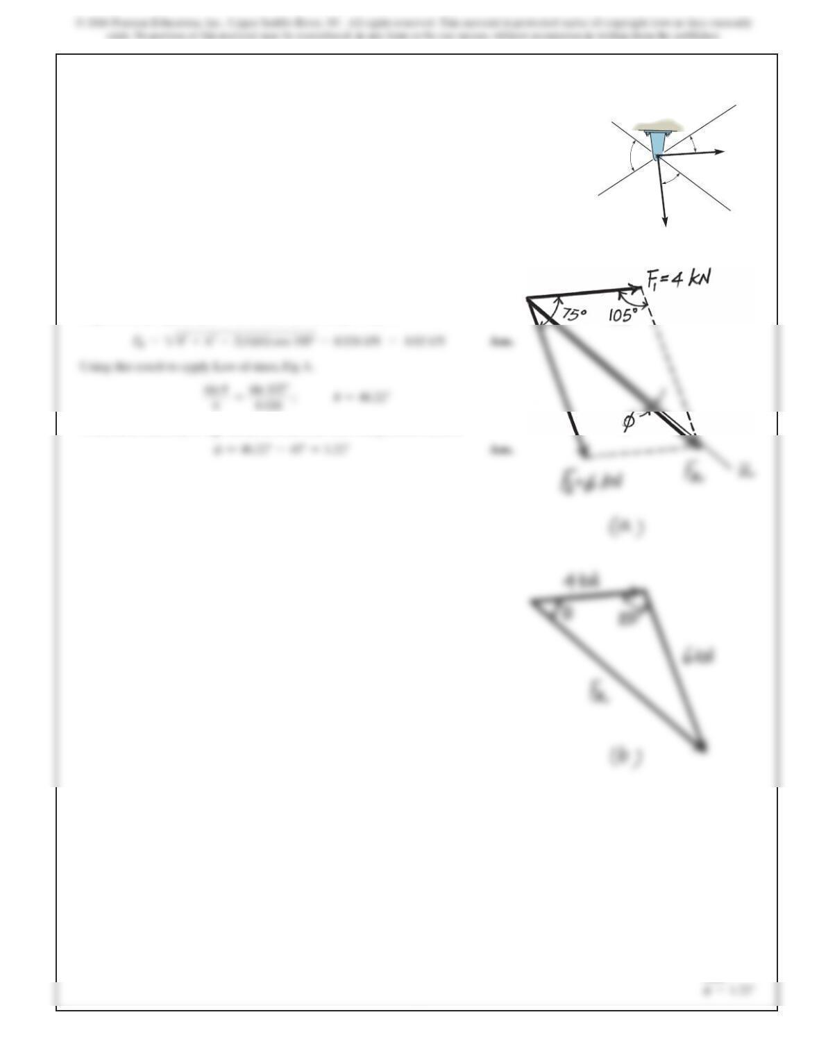
Parallelogram Law: The parallelogram law of addition is shown in Fig. a.
Trigonometry: Using the law of sines (Fig.b), we have
F
B
A
30
45
Ans:
2 7
Ans:
SOLUTION
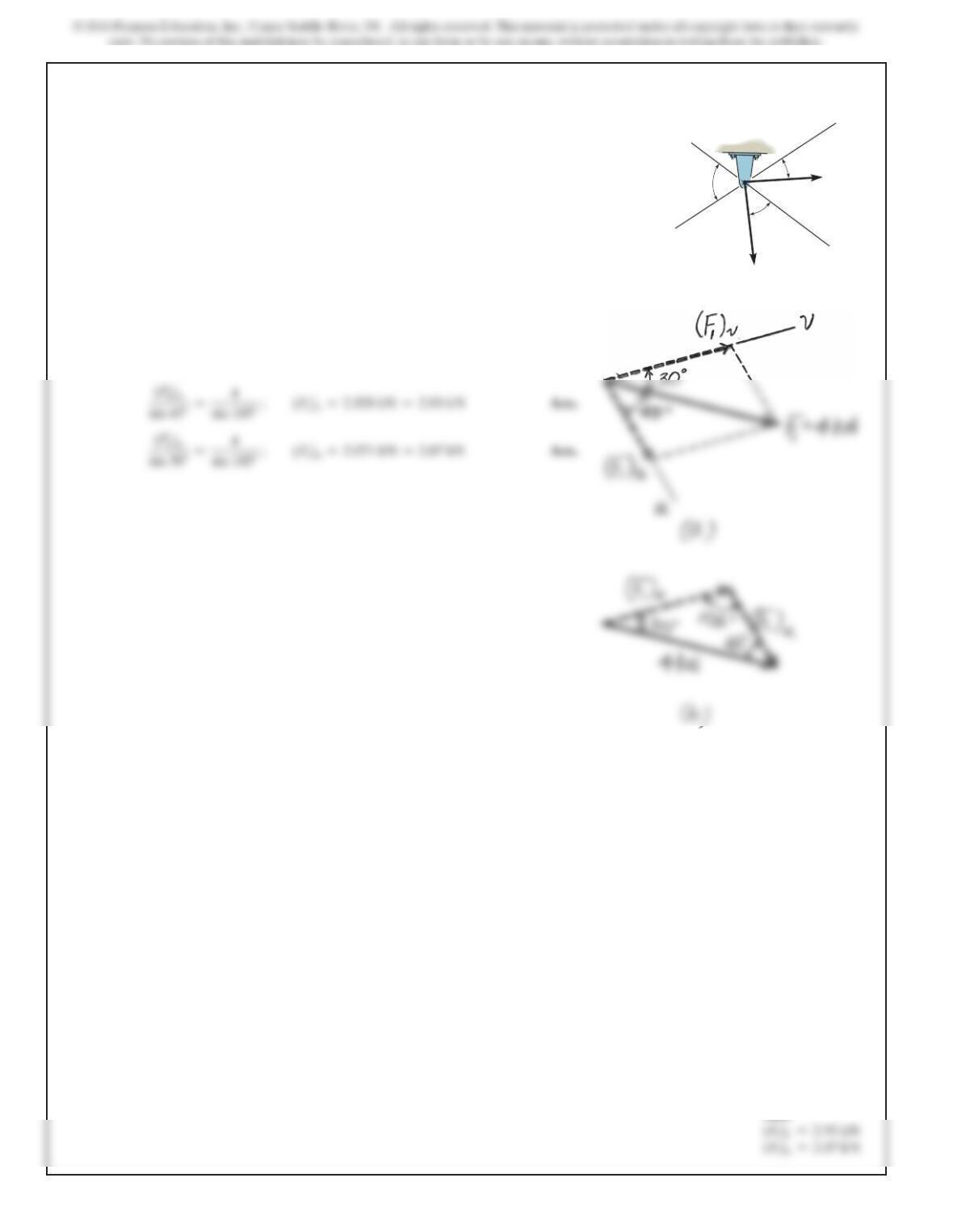
Parallelogram Law. The parallelogram law of addition is shown in Fig. a,
Trigonometry. Applying Law of cosines by referring to Fig. b,
Thus, the direction f of FR measured clockwise from the positive u axis is
2–6.
Determine the magnitude of the resultant force
FR=F1+F2
and its direction, measured clockwise from
the positive u axis.
u
v
75
30
30
F1 4 kN
F2 6 kN
2 8
Ans:
SOLUTION
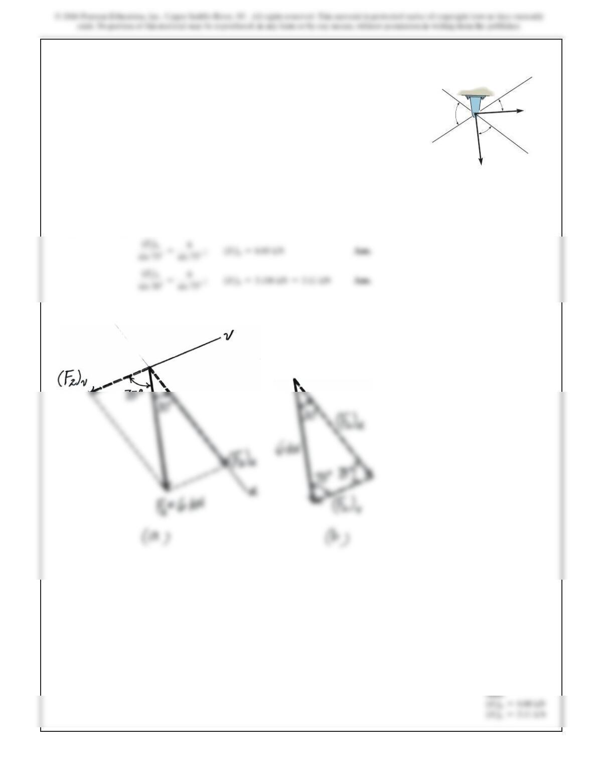
Parallelogram Law. The parallelogram law of addition is shown in Fig. a,
Trigonometry. Applying the sines law by referring to Fig. b.
2–7.
Resolve the force F1 into components acting along the u
and v axes and determine the magnitudes of the components.
u
v
75
30
30
F1 4 kN
F2 6 kN
2 9
SOLUTION
Parallelogram Law. The parallelogram law of addition is shown in Fig. a,
Trigonometry. Applying the sines law of referring to Fig. b,
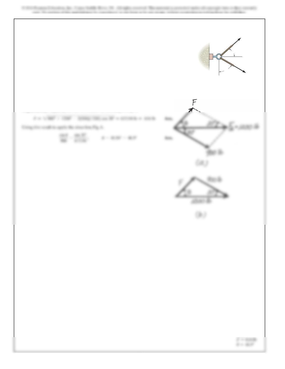
*2–8.
Resolve the force F2 into components acting along the u
and v axes and determine the magnitudes of the components.
u
v
75
30
30
F1 4 kN
F2 6 kN
3 0
Ans:
SOLUTION
Parallelogram Law. The parallelogram law of addition is shown in Fig. a,
Trigonometry. Applying the law of cosines by referring to Fig. b,
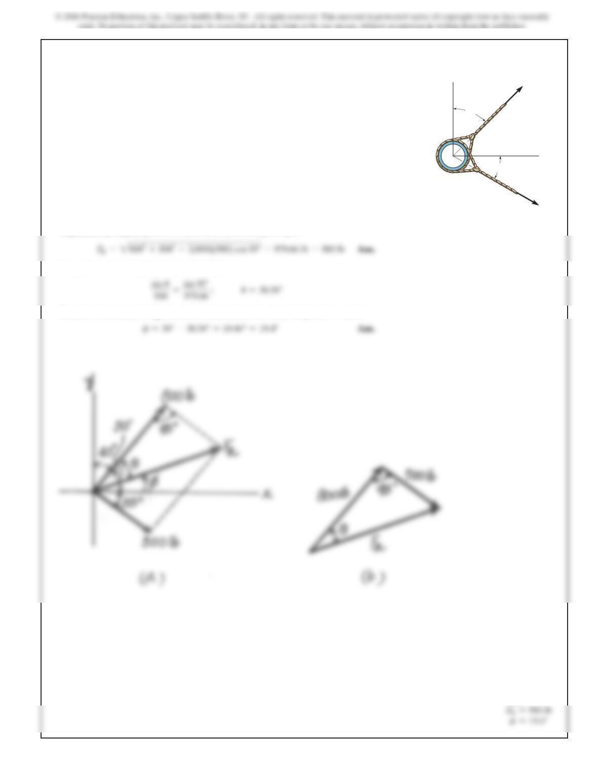
2–9.
If the resultant force acting on the support is to be 1200 lb,
directed horizontally to the right, determine the force F in
rope A and the corresponding angle
u
.
60
900 lb
A
B
F
u
3 1
Ans:
SOLUTION
Parallelogram Law. The parallelogram law of addition is shown in Fig. a,
Trigonometry. Applying the law of cosines by referring to Fig. b,
Using this result to apply the sines law, Fig. b,
Thus, the direction f of FR measured counterclockwise from the positive x axis is
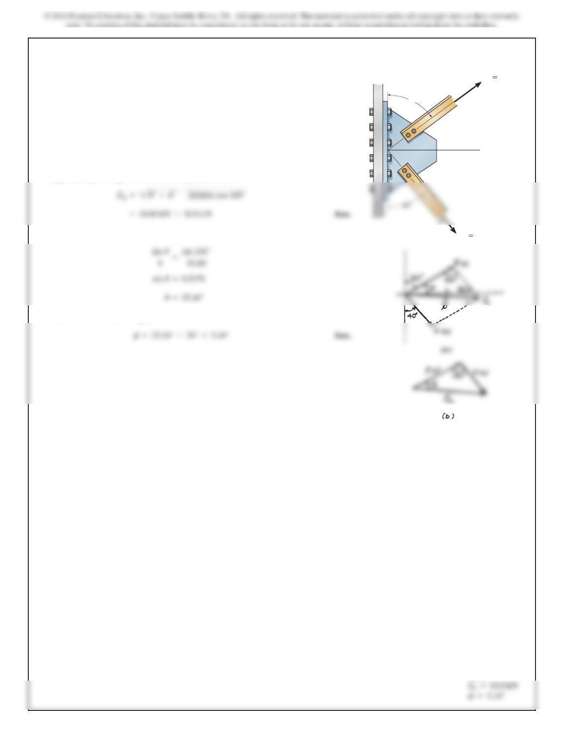
2–10.
Determine the magnitude of the resultant force and its
direction, measured counterclockwise from the positive x axis.
y
x
500 lb
800 lb
35
40
3 2
2–11.
SOLUTION
Parallelogram Law: The parallelogram law of addition is shown in Fig. a.
Trigonometry: Using law of cosines (Fig. b), we have
The angle can be determined using law of sines (Fig. b).
Thus, the direction of FRmeasured from the xaxis is
f
u
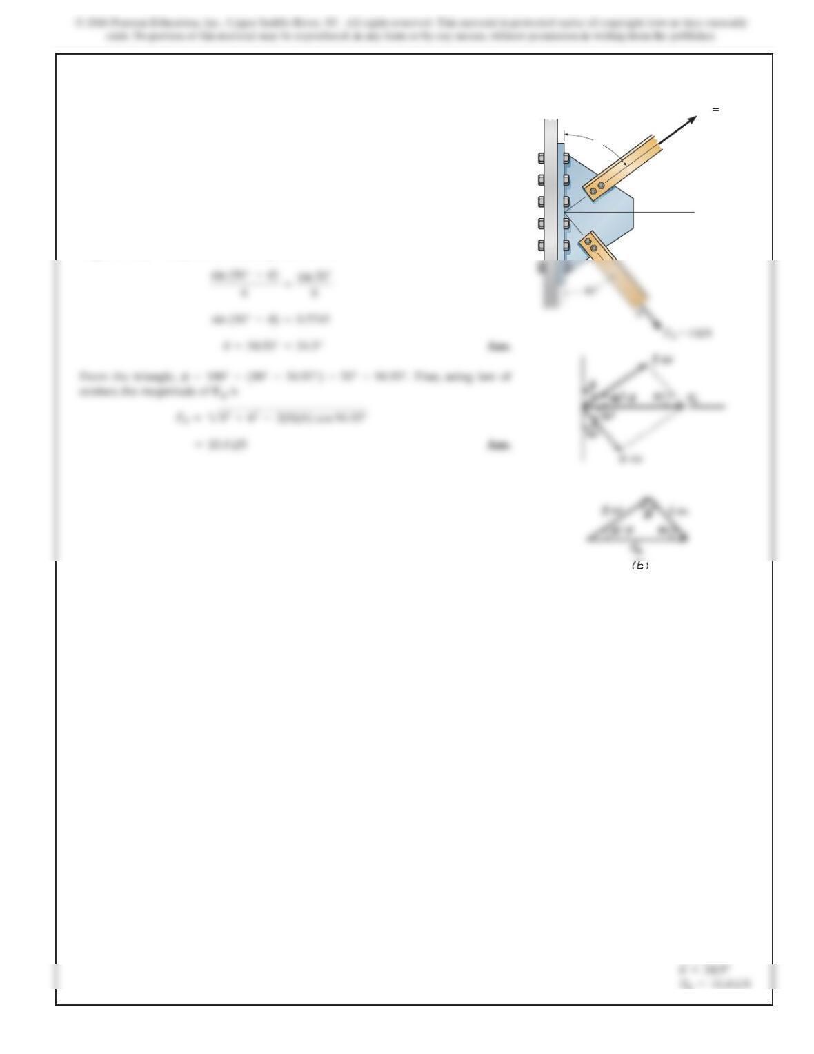
The plate is subjected to the two forces at Aand Bas
shown. If , determine the magnitude of the resultant
of these two forces and its direction measured clockwise
from the horizontal.
u=60°
A
F
A
8kN
F
B
6kN
u
Ans:
3 3
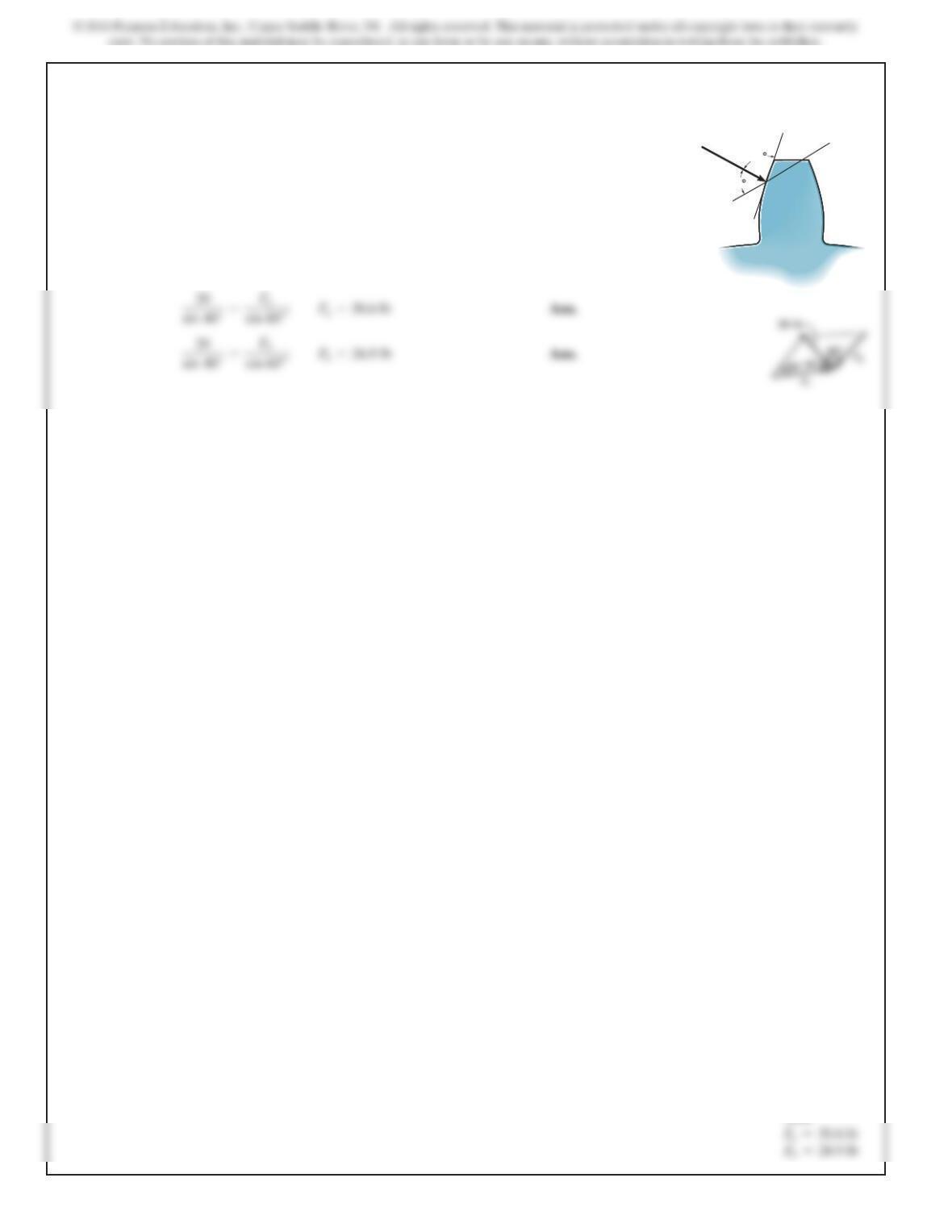
*2–12.
Determ
i
ne t
h
e ang
l
e of for connect
i
ng mem
b
er Ato t
h
e
plate so that the resultant force of FAand FBis directed
horizontally to the right. Also,what is the magnitude of the
resultant force?
u
SOLUTION
Parallelogram Law: The parallelogram law of addition is shown in Fig. a.
Trigonometry: Using law of sines (Fig .b), we have
A
F
A
8kN
u
Ans:
R=10.4 kN
3 4
2–13.
SOLUTION
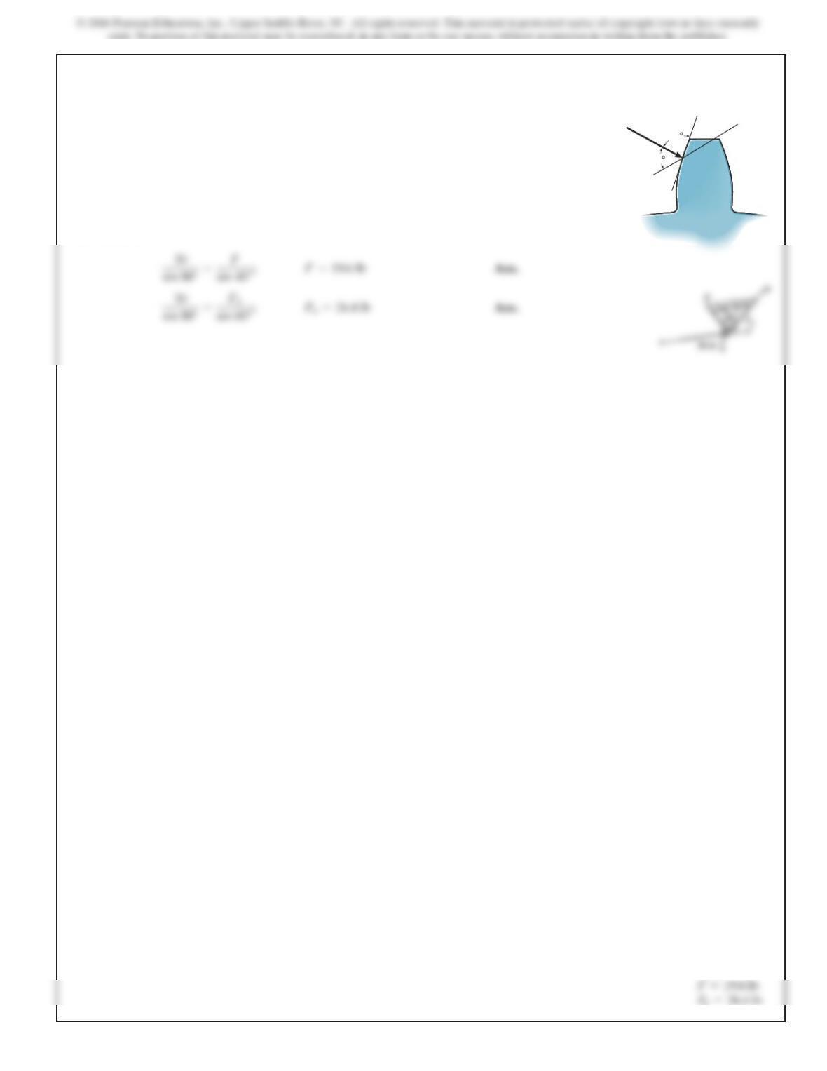
T
h
eforce act
i
ng on t
h
egeartoot
hi
sReso
l
ve
this force into two components acting alongthe linesaa
and bb.
F
=20 lb.
80
60
a
a
b
b
F
Ans:
3 5
2–14.
T
h
e component of force Fact
i
ng a
l
ong
li
ne aa
i
s requ
i
re
d
to
be 30 lb.Determine the magnitude of Fand its component
along line bb.
SOLUTION
80
60
a
a
b
b
F
Ans:
b=26.4
3 6
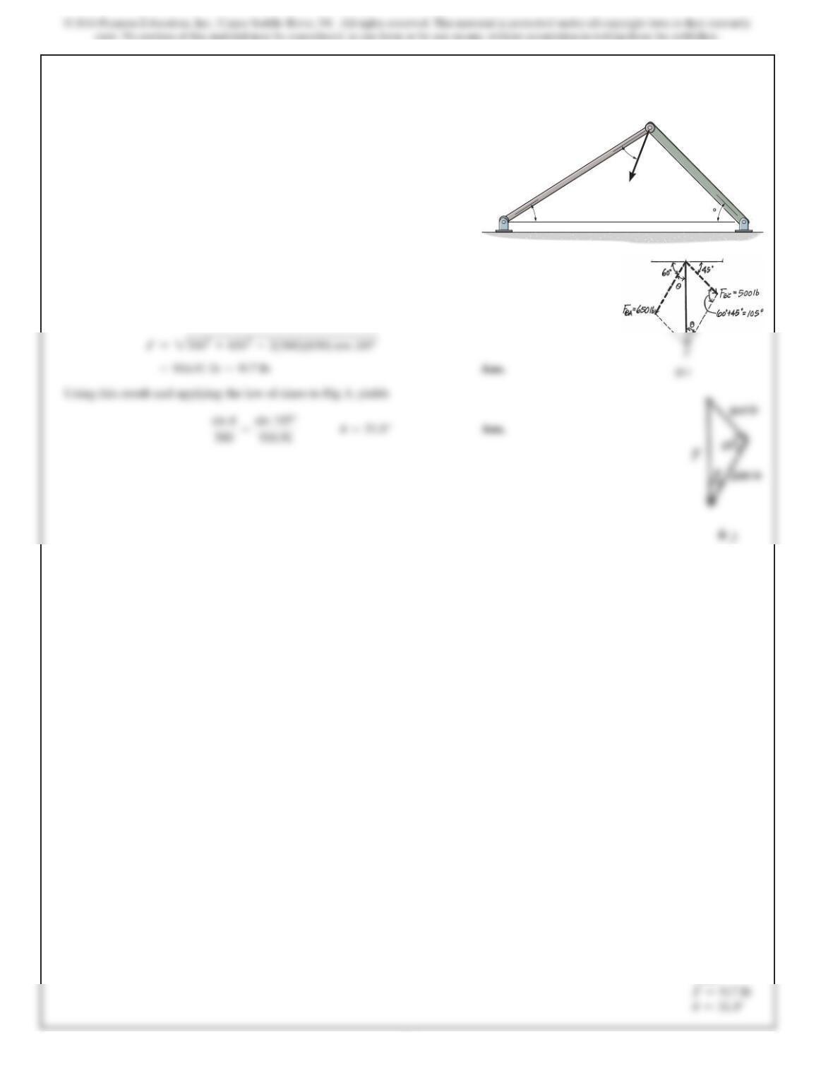
2–15.
SOLUTION
The parallelogram law of addition and triangular rule are shown in Figs. aand b,
respectively.
Applying the law of cosines to Fig. b,
Force Facts on the frame such that its component acting
along member is 650 lb, directed from towards , and
the component acting along member is 500 lb, directed
from towards . Determine the magnitude of Fand its
direction . Set .f=60°u
CB
BC
ABAB
A
B
C
F
45
u
f
Ans:
3 7
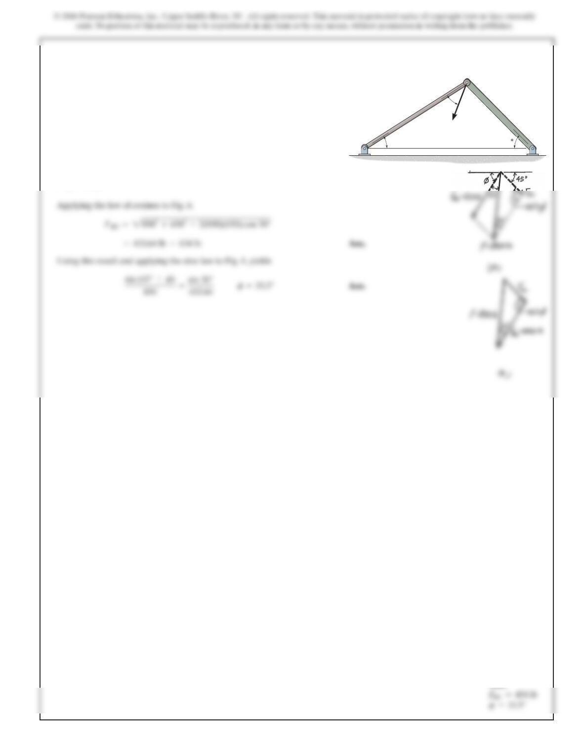
*2–16.
Force Facts on the frame such that its component acting
along member AB is 650 lb, directed from Btowards A.
Determine the required angle and the
component acting along member BC. Set and
.u=30°
F=850 lb
f (0° …f…45°)
SOLUTION
The parallelogram law of addition and the triangular rule are shown in Figs. aand b,
respectively.
A
B
C
F
45
u
f
Ans:
3 8
2–17.
SOLUTION
Determinethe magnitudeand directionofthe resultant
of the three forces by first finding the
resultant and then forming FR=F¿+F3.F¿=F1+F2
FR=F1+F2+F3
y
x
F
2
20 N
F
1
30 N
20
35
4
F
3
50 N
Ans:
3 9
2–18.
Determ
i
ne t
h
emagn
i
tu
d
ean
ddi
rect
i
on of t
h
eresu
l
tant
of the three forces by first finding the
resultant and then forming FR=F¿+F1.F¿=F2+F3
FR=F1+F2+F3
SOLUTION
y
x
F
1
30 N
20
3
5
4
F
3
50 N
Ans:
4 0
2–19.
Determine the design angle for strut AB
so that the 400-lb horizontal force has a component of 500 lb
directed from Atowards C.What is the component of force
acting along member AB?Take .f=40°
u
(0° …
u
…90°)
SOLUTION
Parallelogram Law: The parallelogram law of addition is shown in Fig. a.
Trigonometry: Using law of sines (Fig. b), we have
A
C
B
400 lb
u
f
Ans:
4 1
*2–20.
SOLUTION
Parallelogram Law: The parallelogram law of addition is shown in Fig. a.
Determine the design angle between
struts AB and AC so that the 400-lb horizontal force has a
component of 600 lb which acts up to the left, in the same
direction as from Btowards A.Take .u=30°
f
(0° …
f
…90°)
A
B
400 lb
u
f