Archives: Solution Manual
978-0073398167 Chapter 4 Solution Manual Part 1
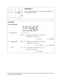
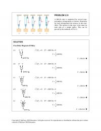
PROBLEM 4.1 For the beam and loading shown, determine (a) the reaction at A, (b) the tension in cable BC. SOLUTION Free–Body Diagram: (a) Reaction at A: 0: 0 xx FAΣ= = 0: (15 lb)(28 in.) (20 lb)(22 in.) (35 […]
978-0073398167 Chapter 3 Solution Manual Part 12
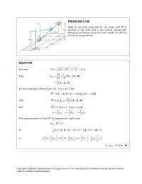
Let the coordinates of Point P be (x in., y in., z in.). Then The requirement that OA and PC be perpendicular implies that Copyright © McGraw–Hill Education. All rights reserved. No reproduction or distribution without the prior written PROBLEM […]
978-0073398167 Chapter 3 Solution Manual Part 11
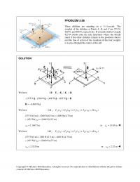
Copyright © McGraw–Hill Education. All rights reserved. No reproduction or distribution without the prior written PROBLEM 3.96 Three children are standing on a 5 5-m raft.× The weights of the children at Points A, B, and C are 375 N, […]
978-0073398167 Chapter 3 Solution Manual Part 10
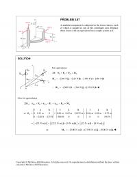
PROBLEM 3.87 A machine component is subjected to the forces shown, each of which is parallel to one of the coordinate axes. Replace these forces with an equivalent force–couple system at A. SOLUTION Copyright © McGraw–Hill Education. All rights reserved. […]
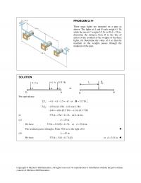
978-0073398167 Chapter 3 Solution Manual Part 9
Copyright © McGraw–Hill Education. All rights reserved. No reproduction or distribution without the prior written consent of McGraw–Hill Education. PROBLEM 3.77 Three stage lights are mounted on a pipe as shown. The lights at A and B each weigh 4.1 […]
978-0073398167 Chapter 3 Solution Manual Part 8
Copyright © McGraw–Hill Education. All rights reserved. No reproduction or distribution without the prior written PROBLEM 3.68 An antenna is guyed by three cables as shown. Knowing that the tension in cable AB is 288 lb, replace the force exerted […]
978-0073398167 Chapter 3 Solution Manual Part 7
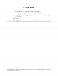
SOLUTION Continued 123 (3.84 2.88 ) 2.40 ( 1.92 1.6 ) (1.92 N m) (1.44 N m) (1.28 N m) MM M M= + + = + − +− − =− ⋅+ ⋅+ ⋅ j k j ik ijk 222 […]
978-0073398167 Chapter 3 Solution Manual Part 6
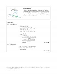
PROBLEM 3.49 Two parallel 60–N forces are applied to a lever as shown. Determine the moment of the couple formed by the two forces (a) by resolving each force into horizontal and vertical components and adding the moments of the […]
978-0073398167 Chapter 3 Solution Manual Part 5
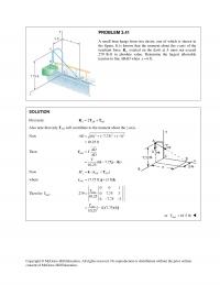
Also note that only TAD will contribute to the moment about the z–axis. or max 61.5 lbT= Copyright © McGraw–Hill Education. All rights reserved. No reproduction or distribution without the prior written consent of McGraw–Hill Education. PROBLEM 3.41 A […]
978-0073398167 Chapter 3 Solution Manual Part 4
PROBLEM 3.31 The 20–in. tube AB can slide along a horizontal rod. The ends A and B of the tube are connected by elastic cords to the fixed point C. For the position corresponding to x = 11 in., determine […]
978-0073398167 Chapter 3 Solution Manual Part 3
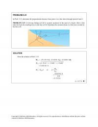
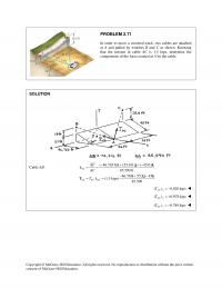
Copyright © McGraw–Hill Education. All rights reserved. No reproduction or distribution without the prior written PROBLEM 3.21 In Prob. 3.15, determine the perpendicular distance from point A to a line drawn through points B and C. PROBLEM 3.15 A 6–ft–long […]
978-0073398167 Chapter 3 Solution Manual Part 2
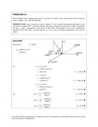
PROBLEM 3.11 Rod AB is held in place by the cord AC. Knowing that the tension in the cord is 1350 N and that c = 360 mm, determine the moment about B of the force exerted by the cord […]
978-0073398167 Chapter 3 Solution Manual Part 1
Copyright © McGraw–Hill Education. All rights reserved. No reproduction or distribution without the prior written PROBLEM 3.1 A 20–lb force is applied to the control rod AB as shown. Knowing that the length of the rod is 9 in. and […]
978-0073398167 Chapter 2 Solution Manual Part 13
Copyright © McGraw–Hill Education. All rights reserved. No reproduction or distribution without the prior written consent of McGraw–Hill Education. PROBLEM 2.107 Knowing that a = 40°, determine the resultant of the three forces shown. SOLUTION 60-lb Force: (60 lb)cos20 56.382 […]
978-0073398167 Chapter 2 Solution Manual Part 12
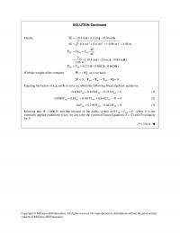
With the weight of the container ,W= −Wj at A we have: 0: 0 AB AC AD WΣ= + + − =F TTT j Equating the factors of i, j, and k to zero, we obtain the following linear algebraic […]
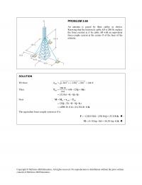
978-0073398167 Chapter 2 Solution Manual Part 11
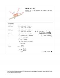
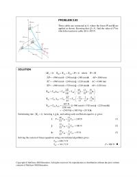
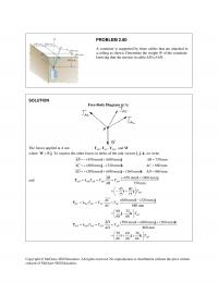
Copyright © McGraw–Hill Education. All rights reserved. No reproduction or distribution without the prior written PROBLEM 2.92 Three cables are connected at A, where the forces P and Q are applied as shown. Knowing that 0,Q= find the value of […]
978-0073398167 Chapter 2 Solution Manual Part 10
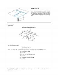
PROBLEM 2.86 Three wires are connected at point D, which is located 18 in. below the T–shaped pipe support ABC. Determine the tension in each wire when a 180–lb cylinder is suspended from point D as shown. SOLUTION Free–Body Diagram […]
978-0073398167 Chapter 2 Solution Manual Part 9
where .W=Wj To express the other forces in terms of the unit vectors i, j, k, we write (450 mm) (600 mm) 750 mm (600 mm) (320 mm) 680 mm (500 mm) (600 mm) (360 mm) 860 mm AB AB […]
978-0073398167 Chapter 2 Solution Manual Part 8
Copyright © McGraw–Hill Education. All rights reserved. No reproduction or distribution without the prior written consent of McGraw–Hill Education. PROBLEM 2.71 In order to move a wrecked truck, two cables are attached at A and pulled by winches B and […]
978-0073398167 Chapter 2 Solution Manual Part 7
Copyright © McGraw–Hill Education. All rights reserved. No reproduction or distribution without the prior written consent of McGraw–Hill Education. PROBLEM 2.61 Solve Problem 2.60, assuming that point A is located 15° north of west and that the barrel of the […]
978-0073398167 Chapter 2 Solution Manual Part 6
Copyright © McGraw–Hill Education. All rights reserved. No reproduction or distribution without the prior written PROBLEM 2.51 A 600–lb crate is supported by several rope- and–pulley arrangements as shown. Determine for each arrangement the tension in the rope. (Hint: The […]
978-0073398167 Chapter 2 Solution Manual Part 5
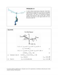
Copyright © McGraw–Hill Education. All rights reserved. No reproduction or distribution without the prior written consent of McGraw–Hill Education. PROBLEM 2.41 A sailor is being rescued using a boatswain’s chair that is suspended from a pulley that can roll freely […]
978-0073398167 Chapter 2 Solution Manual Part 4
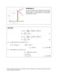
(a) For R to be horizontal, we must have 0. R= Copyright © McGraw–Hill Education. All rights reserved. No reproduction or distribution without the prior written consent of McGraw–Hill Education. PROBLEM 2.31 For the post loaded as shown, determine (a) […]
978-0073398167 Chapter 2 Solution Manual Part 3
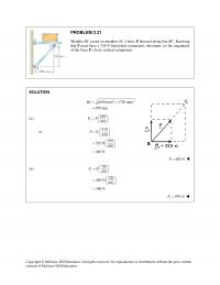
Copyright © McGraw–Hill Education. All rights reserved. No reproduction or distribution without the prior written PROBLEM 2.21 Member BC exerts on member AC a force P directed along line BC. Knowing that P must have a 325–N horizontal component, determine […]
978-0073398167 Chapter 2 Solution Manual Part 2
PROBLEM 2.11 A trolley that moves along a horizontal beam is acted upon by two forces as shown. Determine by trigonometry the magnitude and direction of the force P so that the resultant is a vertical force of 2500 N. […]
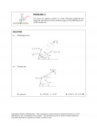
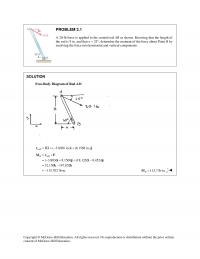
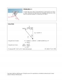
978-0073398167 Chapter 2 Solution Manual Part 1
(a) Parallelogram law: (b) Triangle rule: We measure: 1391 kN, 47.8R α = = ° 1391 N=R 47.8° Copyright © McGraw–Hill Education. This is proprietary material solely for authorized instructor use. Not authorized for sale or distribution in any […]
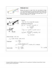
978-0073398167 Chapter 16 Solution Manual Part 7
PROBLEM 16.54 Member AB consists of a single C130 10.4 × steel channel of length 2.5 m. Knowing that the pins at A and B pass through the centroid of the cross section of the channel, determine the factor of […]
978-0073398167 Chapter 16 Solution Manual Part 6
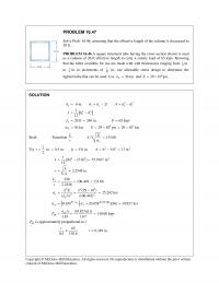
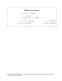
PROBLEM 16.47 Solve Prob. 16.46, assuming that the effective length of the column is decreased to 20 ft. PROBLEM 16.46 A square structural tube having the cross section shown is used as a column of 26–ft effective length to carry […]
978-0073398167 Chapter 16 Solution Manual Part 5
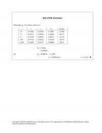
SOLUTION Continued Determine all P for various values of x. x u v P C all (lb)P 1.0 0.73620 0.22240 0.17087 12,920 1.2 0.78513 0.32026 0.24092 26,227 1.1 0.75955 0.26910 0.20473 18,729 1.09 0.75712 0.26423 0.20124 18,075 1.089 0.75687 0.26374 […]
978-0073398167 Chapter 16 Solution Manual Part 4
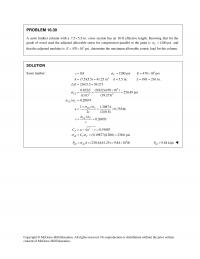
Sawn lumber: 2 0.8 1200 psi 470 10 psi (7.5)(5.5) 41.25 in 5.5 in. 18ft 216 in. / 216/5.5 39.273 C cE A dL Ld = = = × = = = = = = = s 3 22 0.822 […]
978-0073398167 Chapter 16 Solution Manual Part 3
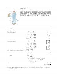
PROBLEM 16.21 Column ABC has a uniform rectangular cross section and is braced in the xz plane at its midpoint C. (a) Determine the ratio b/d for which the factor of safety is the same with respect to buckling in […]
978-0073398167 Chapter 16 Solution Manual Part 2
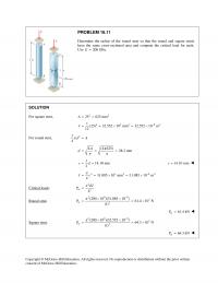
Copyright © McGraw–Hill Education. All rights reserved. No reproduction or distribution without the prior written PROBLEM 16.11 Determine the radius of the round strut so that the round and square struts have the same cross–sectional area and compute the critical […]
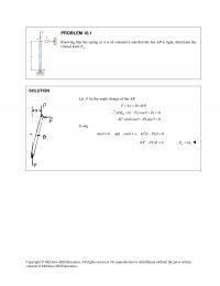
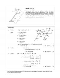
978-0073398167 Chapter 16 Solution Manual Part 1
Let θ be the angle change of bar AB. sinF kx kL θ = = 2 0: cos 0 sin cos sin 0 B M FL Px kL PL θ θθ θ Σ = −= −= Using 2 sin and […]
978-0073398167 Chapter 15 Solution Manual Part 9
Copyright © McGraw–Hill Education. All rights reserved. No reproduction or distribution without the prior written PROBLEM 15.60 For the uniform beam shown, determine the reaction at each of the three supports. SOLUTION Consider C R as redundant and replace loading […]
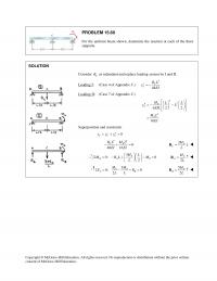
978-0073398167 Chapter 15 Solution Manual Part 8
PROBLEM 15.53 Knowing that beam AE is an S200 27.4× rolled shape and that 17.5 kN, 2.5 m, 0.8 mP La= = = and 200 GPa, E= determine (a) the equation of the elastic curve for portion BD, (b) the […]
978-0073398167 Chapter 15 Solution Manual Part 7
PROBLEM 15.45 The two beams shown have the same cross section and are joined by a hinge at C. For the loading shown, determine (a) the slope at point A, (b) the deflection at point B. Use 6 SOLUTION Using […]
978-0073398167 Chapter 15 Solution Manual Part 6
PROBLEM 15.36 (Continued) Slope at B. 3 15 6.98 10 2148 B θ − = = × 3 6.98 10 rad B θ − = × Deflection at B. 3 28.125 13.09 10 ft 2148 B y − =− […]
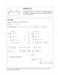
978-0073398167 Chapter 15 Solution Manual Part 5
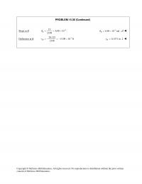
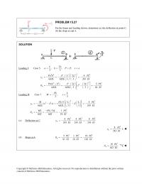
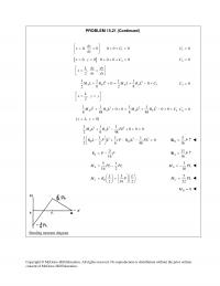
SOLUTION Loading I: Case 5. 2 , ,, 33 LL a b PPxa= = = = 22 22 3 2 22 2 2 24 6 6 3 3 243 () 2 2 5 6 6 3 3 81 C A […]
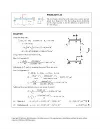
978-0073398167 Chapter 15 Solution Manual Part 4
Copyright © McGraw–Hill Education. All rights reserved. No reproduction or distribution without the prior written PROBLEM 15.21 (Continued) 1 0, 0 0 0 0 dy xC dx = = ++ = 10C= [ ] 2 0, 0000 […]
978-0073398167 Chapter 15 Solution Manual Part 3
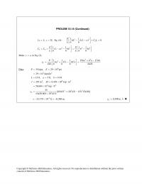
PROLEM 15.14 (Continued) 33 3 11 [ , 0] Eq. (4): ( ) 0 66 P x L y bL L L a C L L = = − −+= 32 32 13 1 1 11 () […]
978-0073398167 Chapter 15 Solution Manual Part 2
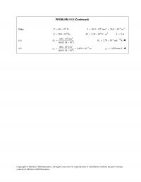
Data: 60 10 N,P= × 26.9 10 mm 26.9 10 mI =×=× 9 200 10 PaE= × 62 5.38 10 N mEI =×⋅ 2mL= (a) 32 6 (60 10 )(2) (16)(5.38 10 ) A θ × =× 3 2.79 10 […]
978-0073398167 Chapter 15 Solution Manual Part 1
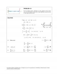
PROBLEM 15.1 For the loading shown, determine (a) the equation of the elastic curve for the cantilever beam AB, (b) the deflection at the free end, (c) the slope at the free end. SOLUTION 0: ( ) 0 J M […]
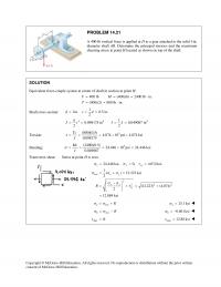
978-0073398167 Chapter 14 Solution Manual Part 9
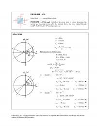
hk θ θθ ≤≤ uv 45 98.13 θ °≤ ≤ ° Also, 135 188.13 and 225 278.13 θθ °≤ ≤ ° °≤ ≤ ° Copyright © McGraw–Hill Education. All rights reserved. No reproduction or distribution without the prior written […]
978-0073398167 Chapter 14 Solution Manual Part 8
Copyright © McGraw–Hill Education. All rights reserved. No reproduction or distribution without the prior written PROBLEM 14.67 (Continued) ave 1( ) 35.69 MPa 2xy σ σσ = += 2 2 9.40 MPa 2 xy xy R σσ τ − […]
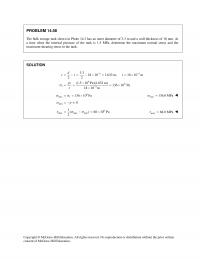
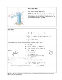
978-0073398167 Chapter 14 Solution Manual Part 7
Copyright © McGraw–Hill Education. All rights reserved. No reproduction or distribution without the prior written PROBLEM 14.58 The bulk storage tank shown in Photo 14.3 has an outer diameter of 3.3 m and a wall thickness of 18 mm. At […]
978-0073398167 Chapter 14 Solution Manual Part 6
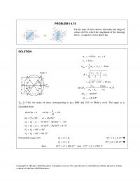
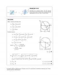
PROBLEM 14.48 Determine the principal planes and the principal stresses for the state of plane stress resulting from the superposition of the two states of stress shown. SOLUTION Mohr’s circle for 2nd stress state: 00 00 0 11 cos 2 […]
978-0073398167 Chapter 14 Solution Manual Part 5
PROBLEM 14.39 Solve Prob. 14.23, using Mohr’s circle. PROBLEM 14.23 The steel pipe AB has a 102–mm outer diameter and a 6–mm wall thickness. Knowing that arm CD is rigidly attached to the pipe, determine the principal stresses and 3 […]
978-0073398167 Chapter 14 Solution Manual Part 4
Copyright © McGraw–Hill Education. All rights reserved. No reproduction or distribution without the prior written consent of McGraw–Hill Education. PROBLEM 14.30 Solve Prob. 14.14, using Mohr’s circle. PROBLEM 14.13 through 14.16 For the given state of stress, determine the normal […]
978-0073398167 Chapter 14 Solution Manual Part 3
PROBLEM 14.21 A 400–lb vertical force is applied at D to a gear attached to the solid l–in. diameter shaft AB. Determine the principal stresses and the maximum shearing stress at point H located as shown on top of the […]
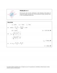
978-0073398167 Chapter 14 Solution Manual Part 2
Copyright © McGraw–Hill Education. All rights reserved. No reproduction or distribution without the prior written PROBLEM 14.11 For the given state of stress, determine (a) the orientation of the planes of maximum in–plane shearing stress, (b) the maximum in–plane shearing […]