Archives: Solution Manual
978-0073398167 Chapter 8 Solution Manual Part 4
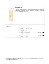
Copyright © McGraw–Hill Education. All rights reserved. No reproduction or distribution without the prior written consent of McGraw–Hill Education. PROBLEM 8.27 The 1.4–kip load P is supported by two wooden members of uniform cross section that are joined by the […]
978-0073398167 Chapter 8 Solution Manual Part 3
(a) Shearing stress in pin at C. 2 τ =BC P F A 22 2 (0.8) 0.5026 in 44 8.9658 8.92 (2)(0.5026) P Ad ππ τ = = = = = 8.92 ksi τ = Copyright © McGraw–Hill Education. […]
978-0073398167 Chapter 8 Solution Manual Part 2
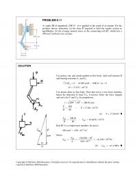
Use piston, rod, and crank together as free body. Add wall reaction H and bearing reactions Ax and Ay. 3 0 : (0.280 m) 1500 N m 0 5.3571 10 N Σ = − ⋅= = × A MH H […]
978-0073398167 Chapter 8 Solution Manual Part 1
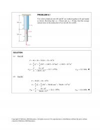
Copyright © McGraw–Hill Education. All rights reserved. No reproduction or distribution without the prior written PROBLEM 8.1 Two solid cylindrical rods AB and BC are welded together at B and loaded as shown. Knowing that 150d= mm and 2 30d= […]
978-0073398167 Chapter 7 Solution Manual Part 8
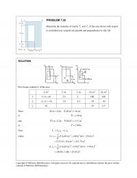
1 108 60 6480×= 54 349,920 2 172 36 1296 2 −× × =− 46 –59,616 Σ 5184 290,304 Then 23 : (5184 mm ) 290,304 mmX A xA XΣ=Σ = or 56.0 mmX= Now 12 () () xx x […]
978-0073398167 Chapter 7 Solution Manual Part 7
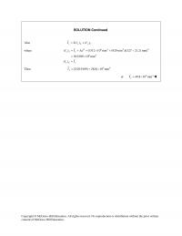
SOLUTION Continued Also 2() () y yL yC II I= + where 2 64 2 2 64 ( ) 0.512 10 mm (929 mm )[(127 21.2) mm] 10.9109 10 mm () yL y yC y I I Ad II =+= […]
978-0073398167 Chapter 7 Solution Manual Part 6
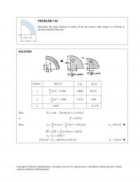
1 (4.5) 15.904 4 = 1.9099 30.375 2 2 (3) 7.069 4 π −=− 1.2732 –9.00 Σ 8.835 21.375 Copyright © McGraw–Hill Education. All rights reserved. No reproduction or distribution without the prior written PROBLEM 7.40 Determine the polar moment […]
978-0073398167 Chapter 7 Solution Manual Part 5
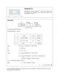
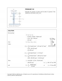
Copyright © McGraw–Hill Education. All rights reserved. No reproduction or distribution without the prior written consent of McGraw–Hill Education. PROBLEM 7.35 Determine the moments of inertia x I and y I of the area shown with respect to centroidal axes […]
978-0073398167 Chapter 7 Solution Manual Part 4
Copyright © McGraw–Hill Education. All rights reserved. No reproduction or distribution without the prior written consent of McGraw–Hill Education. PROBLEM 7.25 Determine the moment of inertia and the radius of gyration of the shaded area with respect to the x […]
978-0073398167 Chapter 7 Solution Manual Part 3
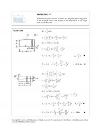
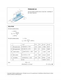
PROBLEM 7.17 Determine the polar moment of inertia and the polar radius of gyration Copyright © McGraw–Hill Education. All rights reserved. No reproduction or distribution without the prior written consent of McGraw–Hill Education. of the rectangle shown with respect to […]
978-0073398167 Chapter 7 Solution Manual Part 2
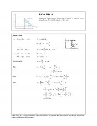
PROBLEM 9.10 Determine the moment of inertia and the radius of gyration of the shaded area shown with respect to the x axis. Then 12 2 sin 4 22( 2) h yh x y xh aa hxa a π = […]
978-0073398167 Chapter 7 Solution Manual Part 1
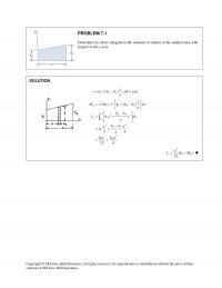
Copyright © McGraw–Hill Education. All rights reserved. No reproduction or distribution without the prior written PROBLEM 7.1 Determine by direct integration the moment of inertia of the shaded area with respect to the y axis. SOLUTION 1 21 ( ); […]
978-0073398167 Chapter 6 Solution Manual Part 15
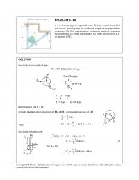
PROBLEM 6.106 A 3–ft–diameter pipe is supported every 16 ft by a small frame like that shown. Knowing that the combined weight of the pipe and its contents is 500 lb/ft and assuming frictionless surfaces, determine the components (a) of […]
978-0073398167 Chapter 6 Solution Manual Part 14
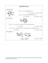
SOLUTION Continued Free body: Joint B: 0: (800 lb)cos16.26 0 y BC FFΣ = − − °= 768.0 lb 768 lb BC BC F FC=−= 0: 3613.8 lb (800 lb) sin16.26° 0 x BD FF Σ= + + = […]
978-0073398167 Chapter 6 Solution Manual Part 13
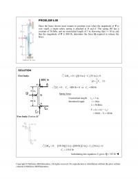
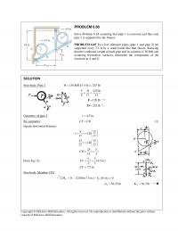
PROBLEM 6.90 Since the brace shown must remain in position even when the magnitude of P is very small, a single safety spring is attached at D and E. The spring DE has a constant of 50 lb/in. and an […]
978-0073398167 Chapter 6 Solution Manual Part 12
Free body: Piston: 0 : ( ) 0 ( ) = y BC y BC y F FP FP = −= ∑ Since BC is two–force member: () () 75 , () () 75 250 250 ( ) =0.3 BC […]
978-0073398167 Chapter 6 Solution Manual Part 11
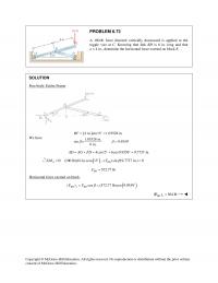
PROBLEM 6.73 A 100–lb force directed vertically downward is applied to the toggle vise at C. Knowing that link BD is 6 in. long and that a = 4 in., determine the horizontal force exerted on block E. SOLUTION Free […]
978-0073398167 Chapter 6 Solution Manual Part 10
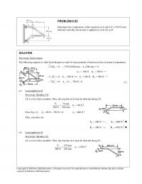
8 15 17 17 25 15 17 17 25 5 15 3 r r CD r CD CD r r += = = = From Eq. (1): 55 (4.5 in.) 33 7.5 in. CF r […]
978-0073398167 Chapter 6 Solution Manual Part 9
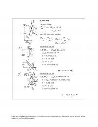
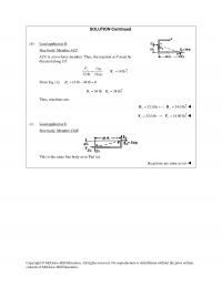
SOLUTION Continued (b) Load applied at D. Free body: Member ACF. directed along CF. 7 in. 14 lb 32 lb 16 in. From Eq. (1): 14 lb 48 lb 0 y B+−= 34 lb 34 lb yy BB= = Thus, […]
978-0073398167 Chapter 6 Solution Manual Part 8
CE is a two-force member. Thus, the reaction at E must be directed along CE. 75 mm 90 N 300 N 250 mm yy EE= = From Eq. (1): 90 N 750 N 0 y A+− = 660 N y […]
978-0073398167 Chapter 6 Solution Manual Part 7
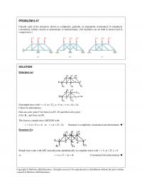
Nonsimple truss with 4,r= 12,m= 8n= so 16 2 .rm n+= = Check for determinacy: One can solve joint F for forces in EF, FG and then solve joint E for y E and force in DE. This leaves a […]
978-0073398167 Chapter 6 Solution Manual Part 6
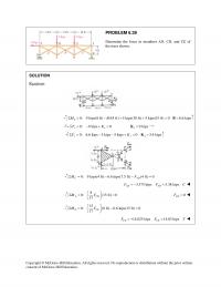
Copyright © McGraw–Hill Education. All rights reserved. No reproduction or distribution without the prior written PROBLEM 6.39 Determine the force in members AD, CD, and CE of the truss shown. SOLUTION Reactions: 0: 9 kips(8 ft) (45 ft) 5 kips(30 […]

978-0073398167 Chapter 6 Solution Manual Part 5
Copyright © McGraw–Hill Education. All rights reserved. No reproduction or distribution without the prior written PROBLEM 6.29 Determine the force in members DE and DF of the truss shown when P = 20 kips. SOLUTION Reactions: 2.5P= =CK 7.5 tan […]
978-0073398167 Chapter 6 Solution Manual Part 4
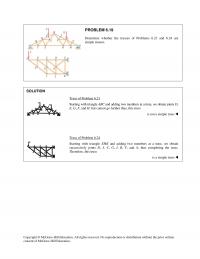
Starting with triangle EHK and adding two members at a time, we obtain successively joints D, J, C, G, I, B, F, and A, thus completing the truss. Therefore, this truss Copyright © McGraw–Hill Education. All rights reserved. No reproduction […]
978-0073398167 Chapter 6 Solution Manual Part 3
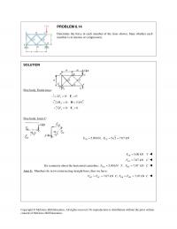
PROBLEM 6.14 Determine the force in each member of the truss shown. State whether each member is in tension or compression. SOLUTION Free body: Entire truss: 0: 0 xx FΣ= =F 0: 5 kN F MΣ= =H 0: 0 yy […]
978-0073398167 Chapter 6 Solution Manual Part 2
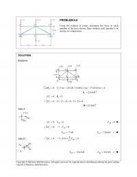
PROBLEM 6.8 Using the method of joints, determine the force in each member of the truss shown. State whether each member is in tension or compression. SOLUTION Reactions: 0: (3 m) (24 kN 8 kN)(1.5 m) (7 kN)(3 m) 0 […]
978-0073398167 Chapter 6 Solution Manual Part 1
PROBLEM 6.1 Using the method of joints, determine the force in each member of the truss shown. State whether each member is in tension or compression. SOLUTION Free body: Entire truss 0: 0 0 x xx FCΣ= = =C 0: […]
978-0073398167 Chapter 5 Solution Manual Part 10
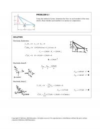
SOLUTION Continued Then 2 22 1ft 2 2 (1.25312 in. ) 144 in. 0.054678 ft s A π = × = Finally Number of gallons 400 0.054678= × 21.87 gallons= Order 22 gallons consent of McGraw–Hill Education. Copyright © […]
978-0073398167 Chapter 5 Solution Manual Part 9
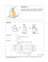
Copyright © McGraw–Hill Education. All rights reserved. No reproduction or distribution without the prior written consent of McGraw–Hill Education. PROBLEM 5.72 A brass collar, of length 2.5 in., is mounted on an aluminum rod of length 4 in. Locate the […]
978-0073398167 Chapter 5 Solution Manual Part 8
I Rectangular plate (5.25)(3)(0.5) 7.875= 0.25− 2.625 1.9688− 20.672 II Rectangular plate (3)(1.5)(0.75) 3.375= 0.75 1.5 2.5313 5.0625 III –(Half cylinder) 2 (0.95) (0.75) 1.063 2 π −=− 1.097 1.5 1.1664− 1.595− IV Half cylinder 2 (1.5) (0.5) 1.767 2 […]
978-0073398167 Chapter 5 Solution Manual Part 7
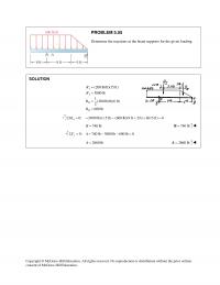
Copyright © McGraw–Hill Education. All rights reserved. No reproduction or distribution without the prior written consent of McGraw–Hill Education. PROBLEM 5.55 Determine the reactions at the beam supports for the given loading. SOLUTION I I II II (200 lb/ft)(15 ft) […]
978-0073398167 Chapter 5 Solution Manual Part 6
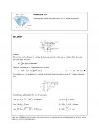
Volume: The volume can be obtained by rotating the triangular area shown through π radians about the y axis. The area of the triangle is: ( )( ) 2 152 60 1560 mm 2 A= = Applying the theorems of […]
978-0073398167 Chapter 5 Solution Manual Part 5
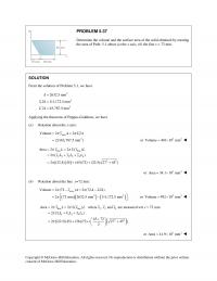
Determine the volume and the surface area of the solid obtained by rotating the area of Prob. 5.1 about (a) the x axis, (b) the line x = 72 mm. Copyright © McGraw–Hill Education. All rights reserved. No reproduction or […]
978-0073398167 Chapter 5 Solution Manual Part 4
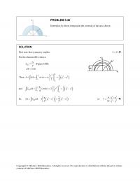
Copyright © McGraw–Hill Education. All rights reserved. No reproduction or distribution without the prior written PROBLEM 5.30 Determine by direct integration the centroid of the area shown. SOLUTION First note that symmetry implies 0x= For the element (EL) shown […]
978-0073398167 Chapter 5 Solution Manual Part 3
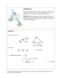
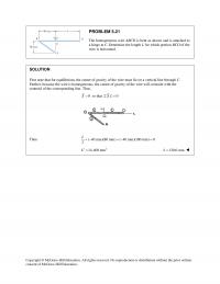
PROBLEM 5.21 The homogeneous wire ABCD is bent as shown and is attached to a hinge at C. Determine the length L for which portion BCD of the wire is horizontal. First note that for equilibrium, the center of gravity […]
978-0073398167 Chapter 5 Solution Manual Part 2
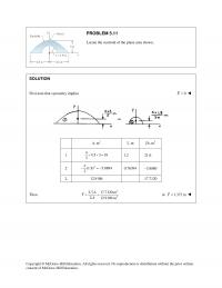
Locate the centroid of the plane area shown. Copyright © McGraw–Hill Education. All rights reserved. No reproduction or distribution without the prior written PROBLEM 5.11 SOLUTION First note that symmetry implies 0X= 2 ,mA ,my 3 ,myA 1 44.5 […]
978-0073398167 Chapter 5 Solution Manual Part 1
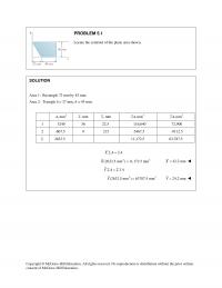
Area 1: Rectangle 72 mm by 45 mm. Area 2: Triangle b = 27 mm, h = 45 mm. 2 , mmA , mmx , mmy 3 ,mmxA 3 ,mmyA 1 3240 36 22.5 116,640 72,900 2 -607.5 9 215 […]
978-0073398167 Chapter 4 Solution Manual Part 14
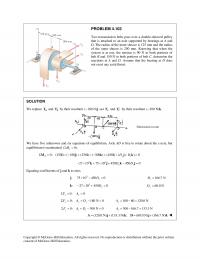
PROBLEM 4.103 Two transmission belts pass over a double–sheaved pulley that is attached to an axle supported by bearings at A and D. The radius of the inner sheave is 125 mm and the radius of the outer sheave is […]
978-0073398167 Chapter 4 Solution Manual Part 13
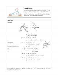
PROBLEM 4.95 Two slender rods of negligible weight are pin-connected at C and attached to blocks A and B, each of weight W. Knowing that 80 θ = ° and that the coefficient of static friction between the blocks and […]
978-0073398167 Chapter 4 Solution Manual Part 12
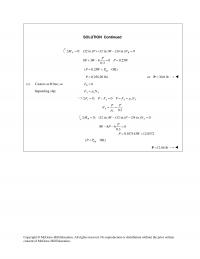
SOLUTION Continued 0: (32 in.) (12 in.) (24 in.) 0 AB M PW NΣ= + − = 8 3 6 0 0.25 0.3 P PW P W +− = = tip ( 0.25 OK)P WP= < 0.25(120 lb)P= or 30.0 […]
978-0073398167 Chapter 4 Solution Manual Part 11
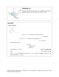
PROBLEM 4.78 Determine whether the block shown is in equilibrium and find the magnitude and direction of the friction force when P = 80 lb. SOLUTION Assume equilibrium: 0: (50 lb)sin 30 (80 lb)cos 40 0 x FFΣ = + […]
978-0073398167 Chapter 4 Solution Manual Part 10
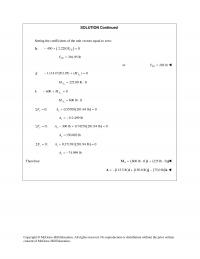
SOLUTION Continued Setting the coefficients of the unit vectors equal to zero: ( ) : 450 2.2283 0 CE F−+ =k 201.95 lb CE F= or 202 lb CE F= : 1.11417(201.95) ( ) 0 A M− +=j y 225.00 […]
978-0073398167 Chapter 4 Solution Manual Part 9
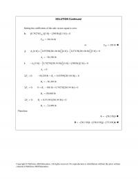
Setting the coefficients of the unit vectors equal to zero: Copyright © McGraw–Hill Education. All rights reserved. No reproduction or distribution without the prior written SOLUTION Continued ( ) ( ) ( )( ) : 0.74278 3 ft 300 lb […]
978-0073398167 Chapter 4 Solution Manual Part 8
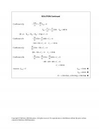
SOLUTION Continued Coefficient of j: 240 240 0 13 17 BD TT−+ = 17 17 (520) 680 lb 13 13 BD BD TT T= = = 0: 320 0 AD AE BF CΣ= + + − + =F TTT j […]
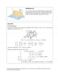
978-0073398167 Chapter 4 Solution Manual Part 7
propped against column CD. It rests at A and B on small wooden blocks and against protruding nails. Neglecting friction at all surfaces of contact, determine the reactions at A, B, and C. Equating the coefficients of the unit vectors […]
978-0073398167 Chapter 4 Solution Manual Part 6
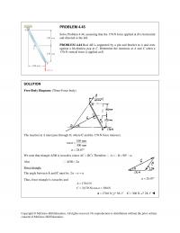
PROBLEM 4.45 Solve Problem 4.44, assuming that the 170–N force applied at B is horizontal and directed to the left. PROBLEM 4.44 Rod AB is supported by a pin and bracket at A and rests against a frictionless peg at […]
978-0073398167 Chapter 4 Solution Manual Part 5
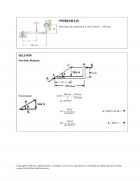
Copyright © McGraw–Hill Education. All rights reserved. No reproduction or distribution without the prior written PROBLEM 4.36 Determine the reactions at A and B when a = 150 mm. SOLUTION Free–Body Diagram: Force triangle 80 mm 80 mm tan 150 […]
978-0073398167 Chapter 4 Solution Manual Part 4
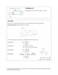
PROBLEM 4.27 Determine the reactions at B and C when a = 30 mm. Copyright © McGraw–Hill Education. All rights reserved. No reproduction or distribution without the prior written SOLUTION Since CD is a two–force member, the force it exerts […]
978-0073398167 Chapter 4 Solution Manual Part 3
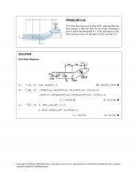
PROBLEM 4.20 Two slots have been cut in plate DEF, and the plate has been placed so that the slots fit two fixed, frictionless pins A and B. Knowing that P = 15 lb, determine (a) the force each pin […]
978-0073398167 Chapter 4 Solution Manual Part 2
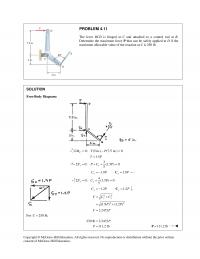
Copyright © McGraw–Hill Education. All rights reserved. No reproduction or distribution without the prior written PROBLEM 4.11 The lever BCD is hinged at C and attached to a control rod at B. Determine the maximum force P that can be […]