Archives
978-1337094740 Chapter 1
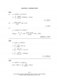
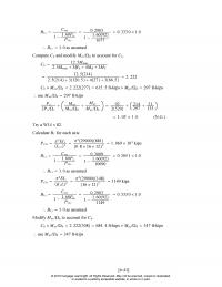
1.5-3 A Pf P A (. ) / . . 0510 4 02043 250 250 02043 1224 2 in. For lb, psi 2 CHAPTER 1 – INTRODUCTION 1.5-1 (a) A (. ) / .0550 4 02376 […]
978-1337094740 Chapter 10 Part 1
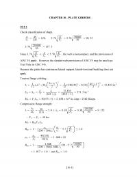
CHAPTER 10 –PLATE GIRDERS 10.4–1 5. 70 29, 000 50 137. 3 Since 3. 76 E Fy h tw 5. 70 E Fy , the web is noncompact, and the provisions of AISC F4 apply. However, the slender-web provisions of […]
978-1337094740 Chapter 10 Part 2
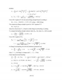
modulus: Ix1 12 twh32Af htf 2 21 12 3/8733257. 573 2. 5 2 2 awhctw bfctfc 733/8 232. 50. 476 1 10 From AISC Equation F5-6, Rpg 1−aw 1200 300aw tw Fy hc −5. 7 E ≤1. 0 1−0. 4761 […]
978-1337094740 Chapter 10 Part 3
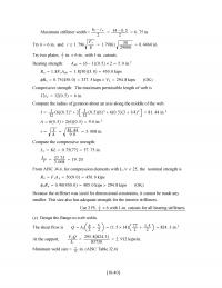
Maximum stiffener width bf−tw 214 −0. 5 26. 75 in. Compute the compressive strength: LcKL 0. 757757. 75 in. Lc r57. 75 3. 008 19. 20 From AISC J4.4, for compression elements with Lc/r25, the nominal strength is RnFyAg509. 0450. […]
978-1337094740 Chapter 2
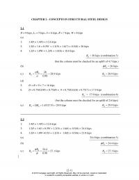
CHAPTER 2 – CONCEPTS IN STRUCTURAL STEEL DESIGN 2-1 D = 9 kips, Lr = 5 kips, S = 6 kips, R = 7 kips, W = 8 kips (a) 1: 1.4D = 1.4(9) = 12.6 kips 3: 1.2D + […]
978-1337094740 Chapter 3 Part 1
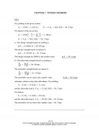
CHAPTER 3 –TENSION MEMBERS 3.2–1 For yielding of the gross section, For rupture of the net section, Ae3/87−13 16 2. 180 in.2 PnFuAe582. 108122. 3 kips a) The design strength based on yielding is tPn0. 9094. 585. 05 kips The […]
978-1337094740 Chapter 3 Part 2
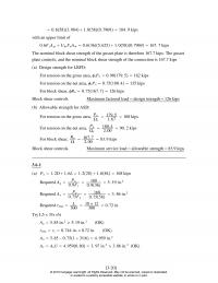
with an upper limit of 0. 6FyAgv UbsFuAnt 0. 6365. 6251. 0580. 7969167. 7 kips The nominal block shear strength of the gusset plate is therefore 167.7 kips. The gusset plate controls, and the nominal block shear strength of the […]
978-1337094740 Chapter 4 Part 1
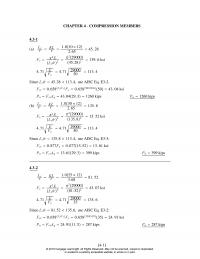
CHAPTER 4 –COMPRESSION MEMBERS 4.3–1 2. 65 45. 28 Fe2E Lc/r2229000 45. 282139. 6 ksi 4. 71 E Fy 4. 71 29000 50 113. 4 Since Lc/r45. 28 113. 4, use AISC Eq. E3-2. Fcr 0. 658Fy/FeFy0. 65850/139.65043. 04 ksi […]
978-1337094740 Chapter 4 Part 2
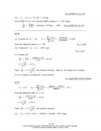
UseanHSS10x8x1/4 (b) PaDL33 82 115 kips 4.7–8 (a) Column AB:GA10, GB∑Icol/Lcol ∑Ig/Lg 2510/20 0. 991 2303/12 From the alignment chart, Kx≈1. 90 Kx1. 90 (b) Column BC:GCGB0. 991 and Kx1. 31 (c) Column AB: Lcx rx KxL 1. 9012 12 […]
978-1337094740 Chapter 5 Part 1
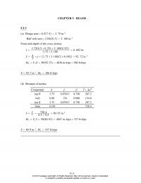
CHAPTER 5 –BEAMS 5.2–1 (a) Flange area 0. 57. 53. 75 in.2 3. 75 3. 188 6. 682 in. ZA 2a3. 75 3. 18826. 68292. 72 in.3 MpFyZ5092. 724636 in-kips 386 ft-kips Z92. 7 in.3,Mp386 ft-kips (b) Moment of inertia: […]
978-1337094740 Chapter 5 Part 2
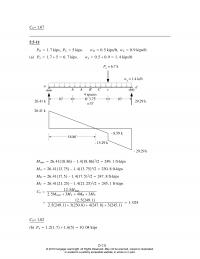
Cb1.67 5.5–11 =15′ 18.86′ 26.41 k 29.29 k 26.41 k – 29.29 k – 8.59 k – 15.29 k Mmax 26. 4118. 86−1. 418. 862/2 249. 1 ft-kips MA26. 4113. 75−1. 413. 752/2 230. 8 ft-kips MB26. 4117. 5−1. 417. […]
978-1337094740 Chapter 5 Part 3
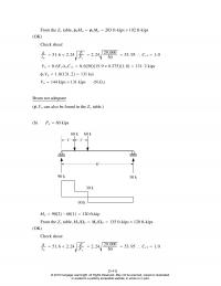
From the Zxtable, bMnbMp203 ft-kips 192 ft-kips (OK) Vu144 kips 131 kips (N.G.) Beam not adequate (vVncan also be found in the Zxtable.) (b) Pa60 kips 6′ 90 k 30 k 1′ 1′ 60 k 60 k 30 k -30 […]
978-1337094740 Chapter 5 Part 4
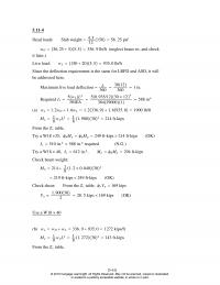
5.11–4 Dead loads: Slab weight 4. 5 12 15056. 25 psf wD56. 25 55. 5336. 9 lb/ft (neglect beam wt. and check it later.) Ix510 in.4588 in.4required (N.G.) Try a W18 40, Ix612 in.4,MnbMp294 ft-kips Check beam weight: Mu214 1 […]
978-1337094740 Chapter 5 Part 5
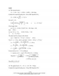
5.14–4 (a) The factored load is 0. 65 0. 853A1 1212 A1 ≥104, A127. 34 in.2 Check upper limit: c1. 7fc´A10. 651. 7327. 3490. 6 kips 104 kips (N.G.) Let c1. 7fc´A1Pu,0.651. 73A1104 A131. 37 in.2 The plate must be […]
978-1337094740 Chapter 6 Part 1
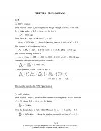
CHAPTER 6 –BEAM–COLUMNS 6.2–1 (a) LRFD solution: From Manual Table 6-2, the compressive design strength of a W12 106 with Fy50 ksi and LcKyL1. 0 14 14 feet is cPn1130 kips From Table 6-2, for Lb14 ft and Cb1. 0, […]
978-1337094740 Chapter 6 Part 2
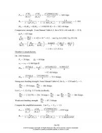
Pe1y2EIy K1L22EIy KyL2229000116 12 1221601 kips B1yCmy 1−Pr/Pe1yCmy 1−1. 00Pu/Pe1y1. 0 1−28. 0/16011. 018 Muy B1Mnty B2Mℓty 1. 018100. 80102. 6 ft-kips Compressive strength: From Manual Table 6-2, for a W10 60 with KL 12 ft, cPn633 kips Pu cPn […]
978-1337094740 Chapter 6 Part 3
Pa 2Pn/c Max Mnx/b May Mny/b 92 2520214 297 31 135 1. 03 1. 0 (N.G.) Try a W14 82. Calculate B1for each axis: Pe1x2EIx Lcx2229000881 0. 8 16 1221. 069 104kips B1xCmx 0. 3009 0. 305 1 1.0 1−1. […]
978-1337094740 Chapter 6 Part 4
br 2Pr Lb 18 125. 776 kips/in. 2. 00 2311. 9 The length of the brace is L18 12/sin21. 80 °581. 6 in. Let AE Lcos2 2Pr Lb 5. 776 A5. 776L Ecos25. 776581. 6 29000 cos221. 8 °0. […]
978-1337094740 Chapter 7 Part 1
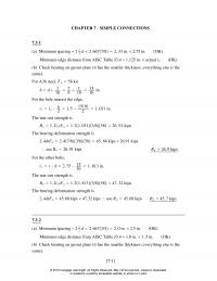
CHAPTER 7 –SIMPLE CONNECTIONS 7.3–1 (a) Minimum spacing 22 3d2. 6677/82. 33 in. 2.75 in. (OK) Minimum edge distance from AISC Table J3.4 1.125 in. actual ℓe(OK) 2. 4dtFu2. 47/83/85845. 68 kips 26.91 kips ∴use Rn26. 91 kips Rn26. 9 […]
978-1337094740 Chapter 7 Part 2
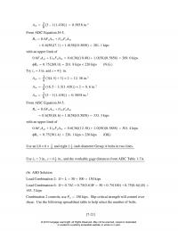
Ant 3 83−11. 438 0. 585 8 in.2 0. 6FyAgv UbsFuAnt 0. 63610. 881. 0580. 5858269. 0 kips Rn0. 75269. 0201. 8 kips 220 kips (N.G.) Try ℓe3 in. and s41 2in. Agv 3 834. 53212. 38 in.2 Anv 3 […]
978-1337094740 Chapter 7 Part 3
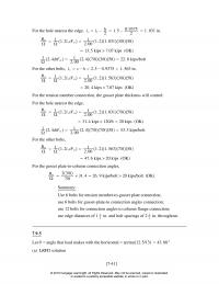
For the hole nearest the edge, ℓcℓ e−h 21. 5 −0. 9375 21. 031 in. Rn 1 1. 2ℓctFu1 2. 00 1. 21. 0313/858 Summary: Use 6 bolts for tension member-to-gusset plate connection; use 6 bolts for gusset-plate-to connection angles […]
978-1337094740 Chapter 7 Part 4
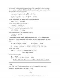
will be used. To determine the required length of the longitudinal welds, investigate 3. 712 28. 29 in. length of longitudinal welds 28. 29 −5 211. 65 in. For the second option, the strength of the longitudinal welds is 0. […]
978-1337094740 Chapter 8 Part 1
CHAPTER 8 –ECCENTRIC CONNECTIONS 8.2–1 Direct shear components: Px3 5159kips, Py4 51512 kips 8.2–2 Eccentricity: ex33410 in., ey5. 5 22. 75 in. ∑x2y2262323262102. 752255. 6 in.2 (a) Direct shear components: PxPucos 30 ° 0. 866 Pu,PyPusin 30 ° 0. 5Pu […]
978-1337094740 Chapter 8 Part 2
Let 0. 062 5Ru29. 82, Ru477 kips The reaction capacity is therefore based on the slip-critical strength. Ru111 kips (b) ASD solution 0. 1Ra7. 380, Ra73. 8 kips Tension: ∑MNA 2rt36236rt MaPae2. 25Ra From 36rt2. 25Ra,rt0. 062 5Ra Interaction of […]
978-1337094740 Chapter 8 Part 3
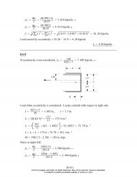
f2xMy J68. 991. 5 28. 67 3. 610 kips/in. 8.4–8 If eccentricity is not considered, f1x150 2677. 895 kips/in. 6″ 2.50″ 7″ 3.5″ 3.5″ x Load when eccentricity is considered: Locate centroid with respect to right side. x […]
978-1337094740 Chapter 8 Part 4
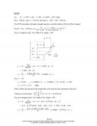
8.4–19 For D 3(w 3/16 in.), Cmin C P 1 u Dℓ 0. 751. 55. 0 239 2. 7 Try a C-shaped weld. Use Table 8-8, Angle 30°. 60º kl l = 9″ 8″ xl ex8−9/2 tan 60 […]
978-1337094740 Chapter 8 Part 5
Shear areas: Agv 1 41. 5 32. 51 492. 25 in.2 Anv 1 0. 6FyAgv UbsFuAnt 0. 6362. 251. 0580. 281364. 92 kips The nominal block shear strength is therefore 64.92 kips. The design block shear strength is Rn0. 7564. […]
978-1337094740 Chapter 8 Part 6
Base metal shear strength of column web: Rupture: Rn0. 45Futw20. 45650. 3702 21. 7 kips/in. 3.00 kips/in. Base metal shear strength of stiffener: Yielding: Rn0. 6Fytst 20. 6363/8216. 2 kips/in. 3.00 kips/in. Rupture: Rn0. 45Futst 20. 45583/8219. 6 kips/in. 3.00 […]
978-1337094740 Chapter 9 Part 1
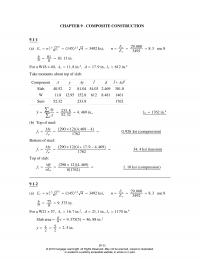
CHAPTER 9 –COMPOSITE CONSTRUCTION 9.1–1 (a) Ecwc 1.5 fc´1451.5 43492 ksi, nEs 29, 000 b n81 810. 13 in. For a W18 40, As11. 8 in.2,d17. 9 in., Ix612 in.4 Take moments about top of slab: Component AyAyĪdĪAd2 Slab 40.52 […]
978-1337094740 Chapter 9 Part 2
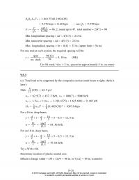
Min. longitudinal spacing 4d40. 52. 0 in. Min. transverse spacing 4d40. 52. 0 in. Max. longitudinal spacing 8t8432 in. (upper limit 36 in.) For one stud at each section, the required spacing will be sspan no. studs 4012 94 5. […]
978-1337094740 Chapter 9 Part 3
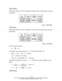
LRFD Solution: Interpolate in Table 3-19. First, interpolate vertically (create an intermediate row), then horizontally. 378.400 428.488 439.135 442.424 305.000 405.000 416.000 bMn439 ft-kips ASD Solution: Interpolate in Table 3-19. First, interpolate vertically (create an intermediate row), then horizontally. Y2 […]
978-1337094740 Chapter 9 Part 4
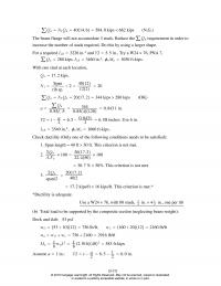
∑QnN1Qn4014. 6584. 0 kips 662 kips (N.G.) The beam flange will not accomodate 3 studs. Reduce the ∑Qnrequirement in order to increase the number of studs required. Do this by using a larger shape. 0. 85fc´b344 0. 8541200. 843 1 […]