Base metal shear strength of column web:
Rupture: Rn0. 45Futw20. 45650. 3702
8.8–1
(a) LRFD solution
Factored shear and moment:
Vu1. 20. 25 271. 60. 75 2740. 5 kips
Mu1. 20. 25 671. 60. 75 67100. 5 ft-kips
Is required moment strength at least 60% of available moment strength?
Tensile strength: Ab0. 752/4 0. 441 8 in.2
RnFntAb0. 75900. 441829. 82 kips/bolt 22.6 kips/bolt (OK)
Shear load per bolt 40. 5/4 10. 13 kips (compression side bolts)
Bearing strength: Assume that the bearing deformation strength of 2.4dtFucontrols and
[8-94]
© 2018 Cengage Learning®. All Rights Reserved. May not be scanned, copied or duplicated,
or posted to a publicly accessible website, in whole or in part.
that column flange thickness controls (tf0. 435 in.).
Is required moment strength at least 60% of available moment strength?
Mn
Mp
82. 8 ft-kips, 0. 6082. 849. 7 ft-kips
8.8–2
LRFD solution
Factored shear and moment:
Vu1. 20. 25 531. 60. 75 5379. 5 kips
Mu1. 20. 25 1341. 60. 75 134201. 0 ft-kips
Is required moment strength at least 60% of available moment strength?
8.8–3
LRFD solution
From the Zxtables, for a W18 40,
MubMpx 294 ft-kips
VuvVn169 kips
Fth0h12294 12
0. 759019. 64 15. 110. 979 in.
Try db1 inch.
[8-96]
© 2018 Cengage Learning®. All Rights Reserved. May not be scanned, copied or duplicated,
or posted to a publicly accessible website, in whole or in part.
Moment strength based on bolt strength:
PtFtAb9012/4 70. 69 kips/bolt
6. 02 17. 02 in.
Try bp7 in. Compute the required plate thickness:
s1
215. 11 1
21
2. 475 19. 64 1
2−1
22
3. 5 15. 1122. 475
119. 1
Required tp1. 11Mn
bFyYp
1. 113528
0. 936119. 11. 01 in.
Try tp1¼ inch.
0. 6FuAn0. 750. 6585. 781150. 9 kips 101.6 kips (OK)
Check bolt shear. The compression side bolts must be capable of resisting the entire
vertical shear.
Abdb
2
Recompute the plate dimensions. For 1¼-inch diameter bolts,
minimum ℓe15
8in.
The minimum plate width is
g2ℓe3. 50 21. 6256. 75 in.
Tearout: Rn1. 2ℓctFu0. 751. 23. 0871. 2558201. 4 kips
Bearing deformation: 2. 4dtFu0. 752. 41. 251. 2558163. 1 kips
Since the inner bolts are not near an edge or adjacent bolts, the outer bolts control for
[8-98]
© 2018 Cengage Learning®. All Rights Reserved. May not be scanned, copied or duplicated,
or posted to a publicly accessible website, in whole or in part.
bearing. However, the shear strength of 49. 69 kip/bolt controls for each bolt.
8222 1 5
825 1
8in.
UseaPL1¼72′−11
8
′′
and four 1¼-inch diameter Group A fully-tightened bolts at each flange.
1. 392D11. 73 1. 5 203. 1, D8. 29 sixteenths
From AISC Table J2.4, the minimum weld size is ¼ in. (based on the thickness of the
1. 392D20. 6Fytw
1. 39220. 6500. 315
1. 39223. 39 sixteenths
1. from mid-depth to the compression flange:
2. from the inner row of tension bolts plus 2dbto the compression flange:
1. 392D8. 425 2169, D7. 21 sixteenths (w½ in.)
From AISC Table J2.4, the minimum weld size is 3/16 in.
Use a ½-inch fillet weld on each side of the web
between mid-depth and the compression flange.
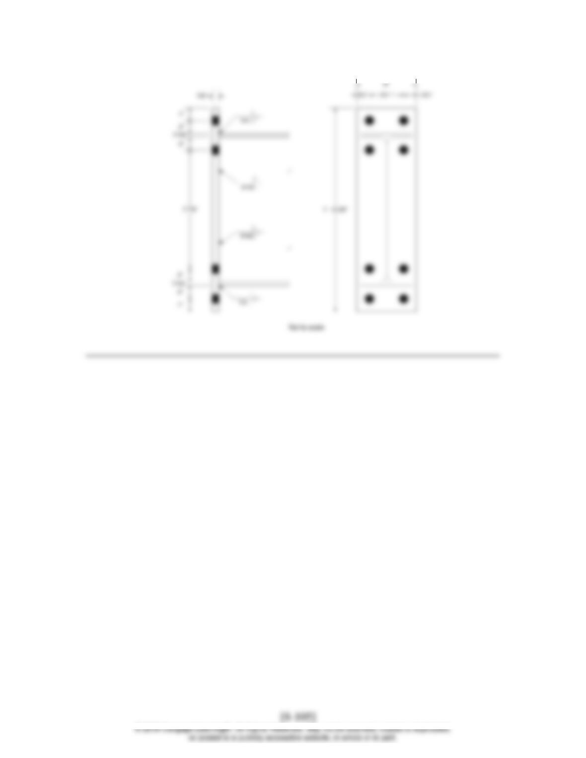
The design is summarized in the figure below.
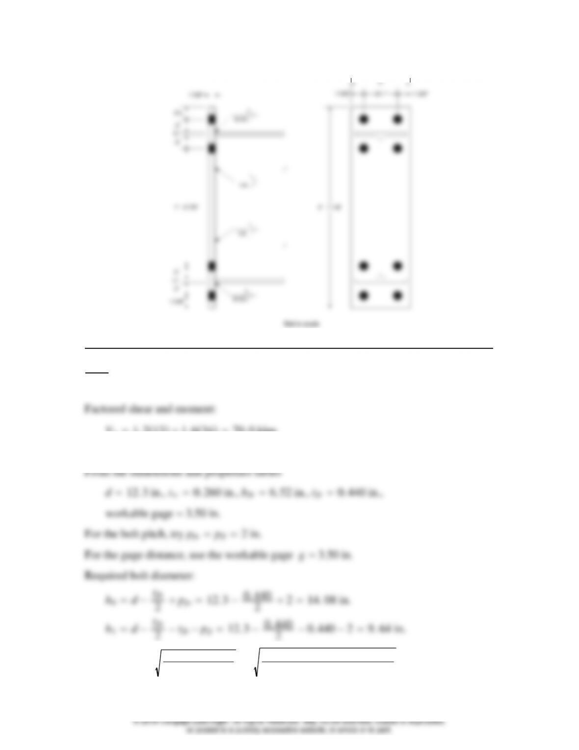
7″
9/16
2″
1 5/8″
Not to scale
8.8–4
LRFD solution
Vu1. 2131. 63470. 0 kips
Mu1. 2201. 648100. 8 ft-kips
dbReq′d2Mu
Fth0h12100. 8 12
0. 759014. 08 9. 640. 694 in.
[8-101]
© 2018 Cengage Learning®. All Rights Reserved. May not be scanned, copied or duplicated,
or posted to a publicly accessible website, in whole or in part.
s1
2bpg1
27. 523. 5
2. 565 in. pfi ∴use the original value of pfi 2. 0 in.
Ypbp
pfi
1
sh01
pfo
−1
gh1pfi s
29. 64 1
21
2. 565 14. 08 1
2−1
22
3. 5 9. 6422. 565
81. 99
Required tp1. 11Mn
bFyYp
1. 111415
0. 903681. 990. 769 in.
87. 52 −23
41
85. 049 in.2
0. 6FuAn0. 750. 6585. 049132 kips 51 kips (OK)
[8-102]
© 2018 Cengage Learning®. All Rights Reserved. May not be scanned, copied or duplicated,
or posted to a publicly accessible website, in whole or in part.
Check bolt shear. The compression side bolts must be capable of resisting the entire
vertical shear.
2
ℓcpfo tfb pfi −h20. 440 2−13/16 3. 628 in.
Tearout: Rn1. 2ℓctFu0. 751. 23. 6287/858165. 7 kips
Bearing deformation: 2. 4dtFu0. 752. 43/47/85868. 51 kips
Since the inner bolts are not near an edge or adjacent bolts, the outer bolts control.
Shear controls overall.
881′−63
8
4-inch diameter Group A fully-tightened bolts at
each flange.
AISC Design Guide 4 recommends that the minimum design flange force should be
1. 392D12. 78 1. 5 102. 0, D3. 82 sixteenths
From AISC Table J2.4, the minimum weld size is 3/16 in. (based on the thickness of
1. 392D20. 6Fytw
1. 39220. 6500. 260
1. 39222. 80 sixteenths
Minimum size 3/16 in., based on web thickness.
1. from mid-depth to the compression flange:
2. from the inner row of tension bolts plus 2dbto the compression flange:
1. 392D5. 71 270, D4. 40 sixteenths
Use a 5/16-inch fillet weld on each side of the web between mid-depth and
the compression flange.
The design is summarized in the following figure .
[8-104]
© 2018 Cengage Learning®. All Rights Reserved. May not be scanned, copied or duplicated,
or posted to a publicly accessible website, in whole or in part.
8″