Let 0. 062 5Ru29. 82, Ru477 kips
The reaction capacity is therefore based on the slip-critical strength. Ru111 kips
(b) ASD solution
0. 1Ra7. 380, Ra73. 8 kips
Tension:
Let 0. 062 5Ra19. 88, Ra318 kips
The reaction capacity is therefore based on the slip-critical strength. Ra73. 8 kips
8.3–8
Assume that tension controls. Select bolt size based on tension, then check the other
Required diameter db4Ab
40. 5744
0. 855 2 in.
Try 7
8-in. diameter bolts, with Ab7/82/4 0. 601 3 in.2
Slip-critical strength will control over shear. In this type of connection, the tensile
22−15/16
21. 531 in.
Rn1. 2ℓctFu0. 751. 21. 5310. 59065
52. 8 kips 8.88 kips (OK)
2. 4dtFu0. 752. 47/80. 5906560. 4 kips/bolt 52.8 kips
From 42rt903, rt21. 5 kips
[8-22]
© 2018 Cengage Learning®. All Rights Reserved. May not be scanned, copied or duplicated,
or posted to a publicly accessible website, in whole or in part.
Total tensile load per bolt 4. 7 21. 5 26. 2 kips. Let
Fnt 26. 2
Ab
Ab26. 2
DuTbnb
1. 1339100. 940 5
kscRn/0. 940511. 5310. 84 kips/bolt 60/10 6 kips/bolt (OK)
Check bearing (flange of WT controls). h11
89
8in.
8.3–9
(a) Factored load: Neglect the beam weight initially, and account for it later.
wu1. 2wD1. 6wL1. 646. 4 kips/ft
Mu1
8wuL21
86. 4302720 ft-kips
Let 35. 79NbVu: 35. 79Nb97. 4 Nb2. 72
Try 4 bolts in beam-to-angle connection and 8 bolts in angle-to-column connection.
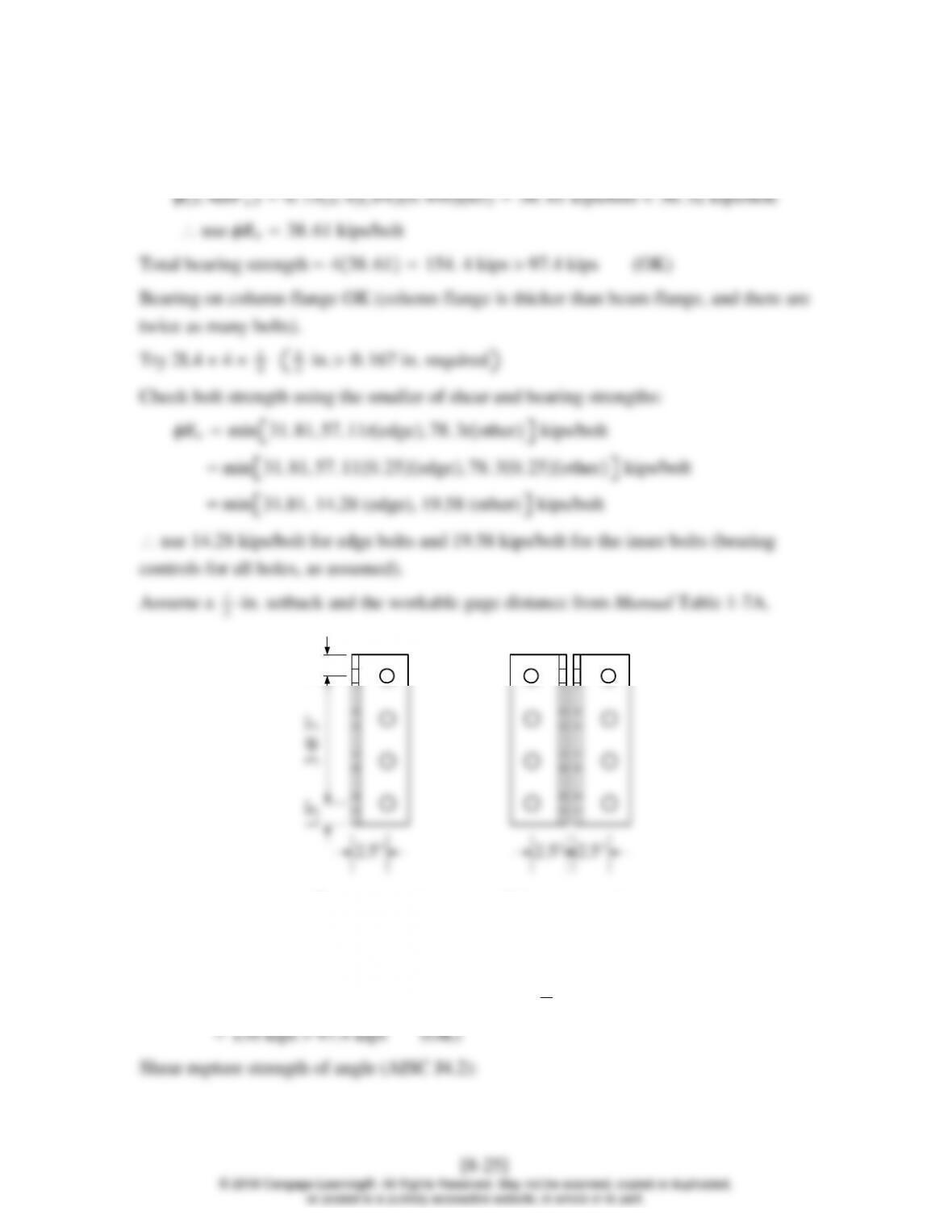
Use a minimum spacing of 3d33/42. 25 in.
Minimum edge distance from AISC Table J3.4 1in.
Let 584. 0tVu97. 4 t0. 167 in.
[8-24]
© 2018 Cengage Learning®. All Rights Reserved. May not be scanned, copied or duplicated,
or posted to a publicly accessible website, in whole or in part.
Check beam web. tw0. 440 in. There are no edge bolts. For the other bolts,
Rn1. 2ℓctFu0. 751. 22. 1880. 4406556. 32 kips/bolt
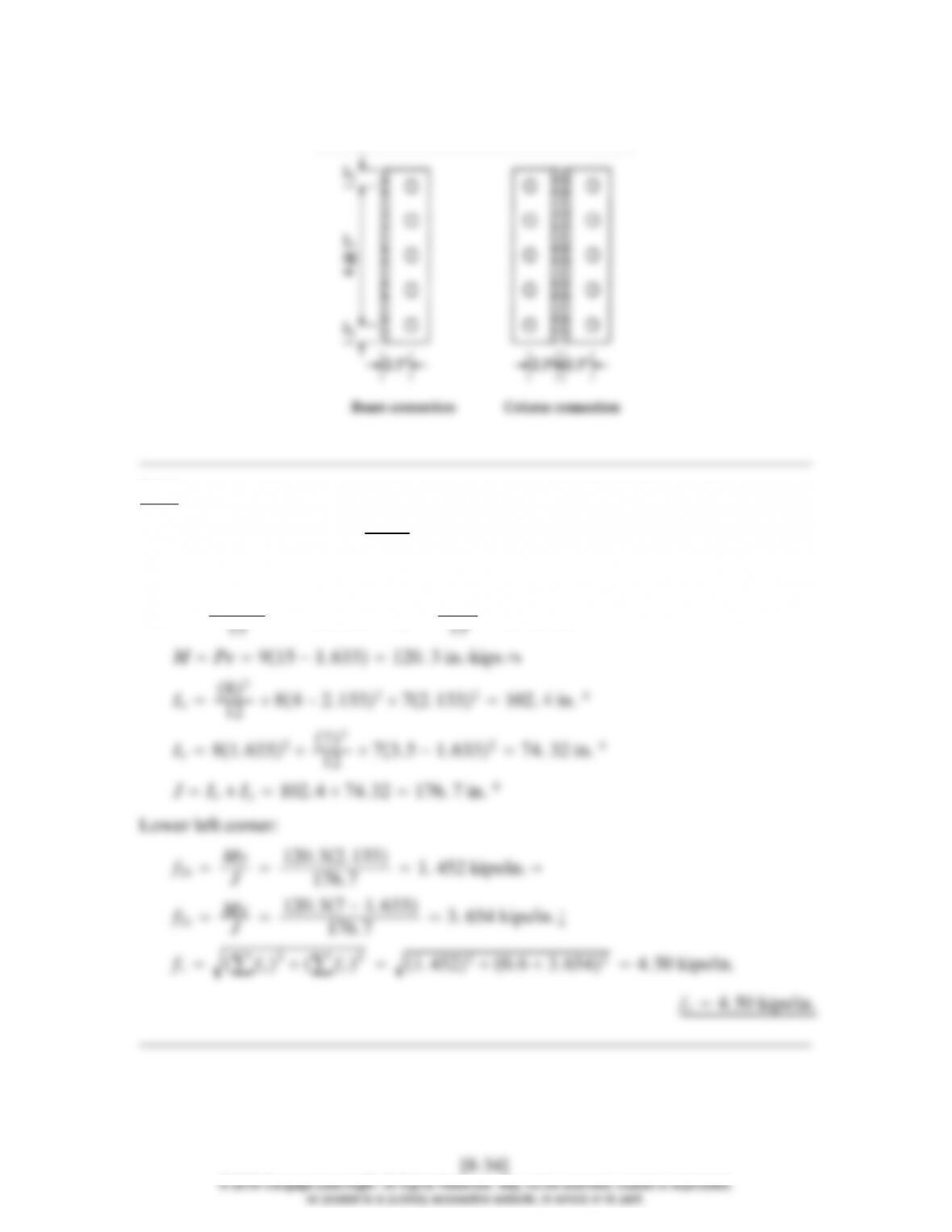
Beam connection Column connection
Shear yield strength of angles (AISC J4.2):
Rn0. 60FyAg21. 00. 603612 1
42
0. 6FyAgv UbsFuAnt 0. 6365. 251. 0580. 5313144. 2 kips
Rn0. 75144. 2108 kips 97. 4 kips (OK)
Use 2L4 41
4as shown, with four 3
4-in. diameter A325
bearing-type bolts in the beam web, and eight 3
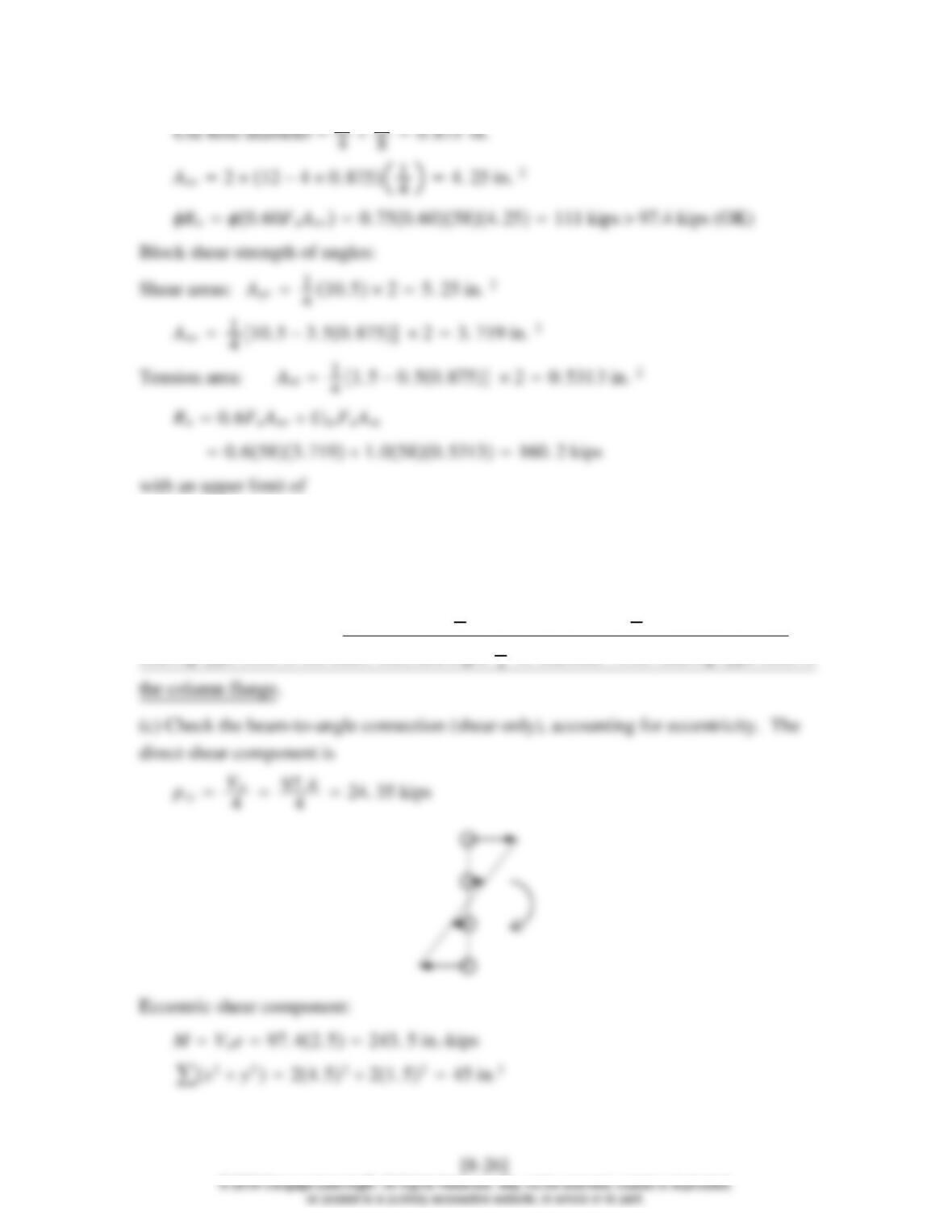
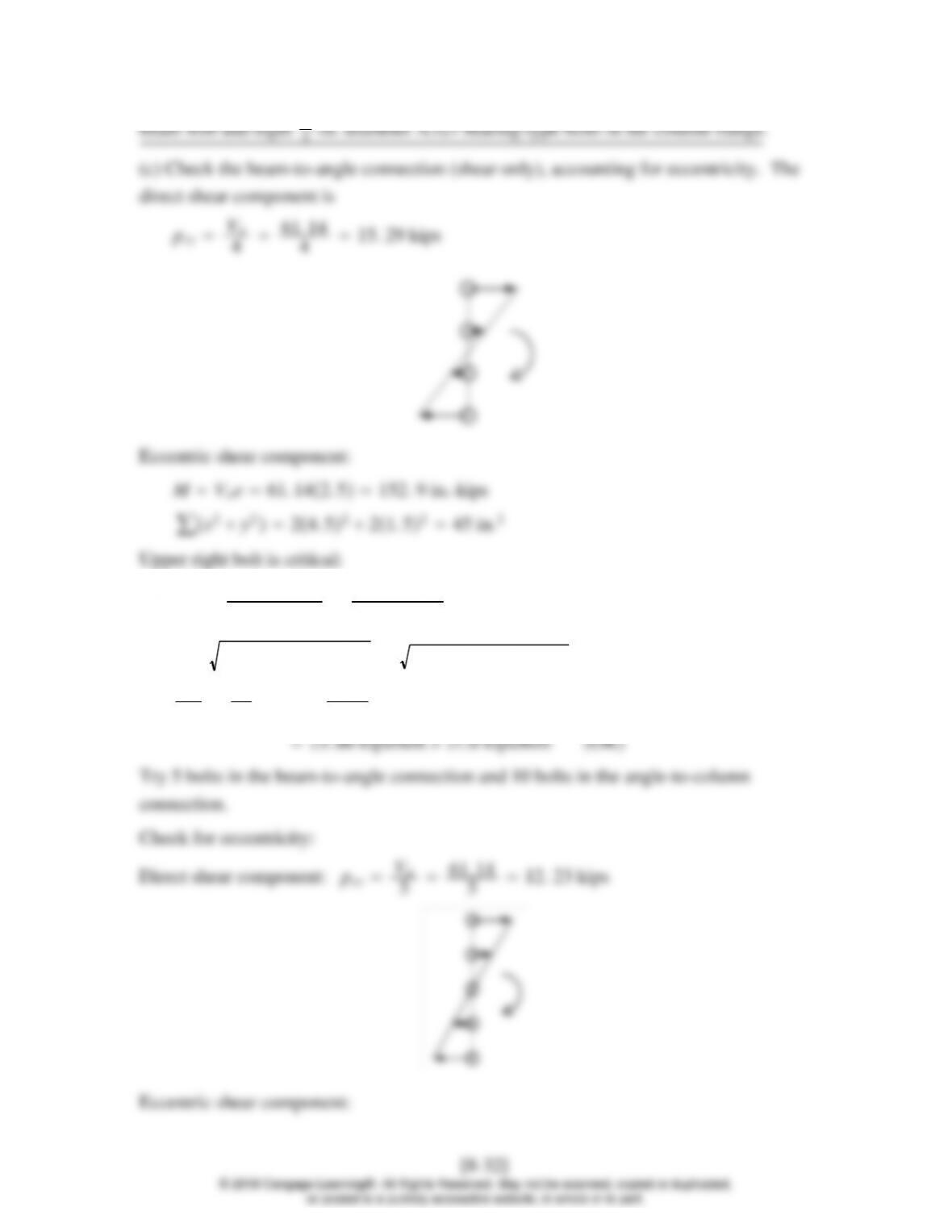
Upper right bolt is critical:
pmx My
∑x2y2243. 54. 5
45 24. 35 kips
p∑px2∑py224. 35224. 35234. 4 kips
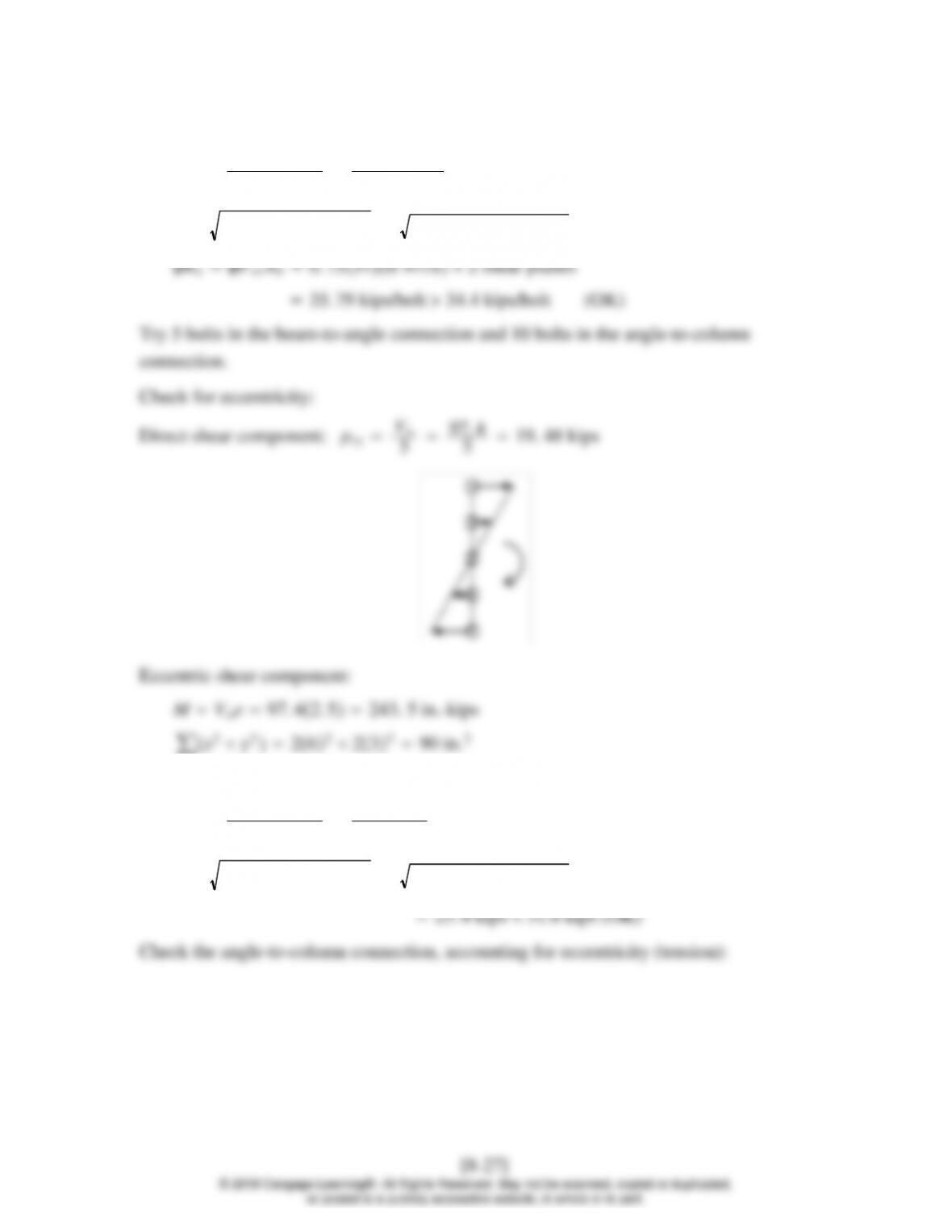
Upper right bolt is critical:
pmx My
∑x2y2243. 56
90 16. 23 kips
p∑px2∑py216. 23219. 482
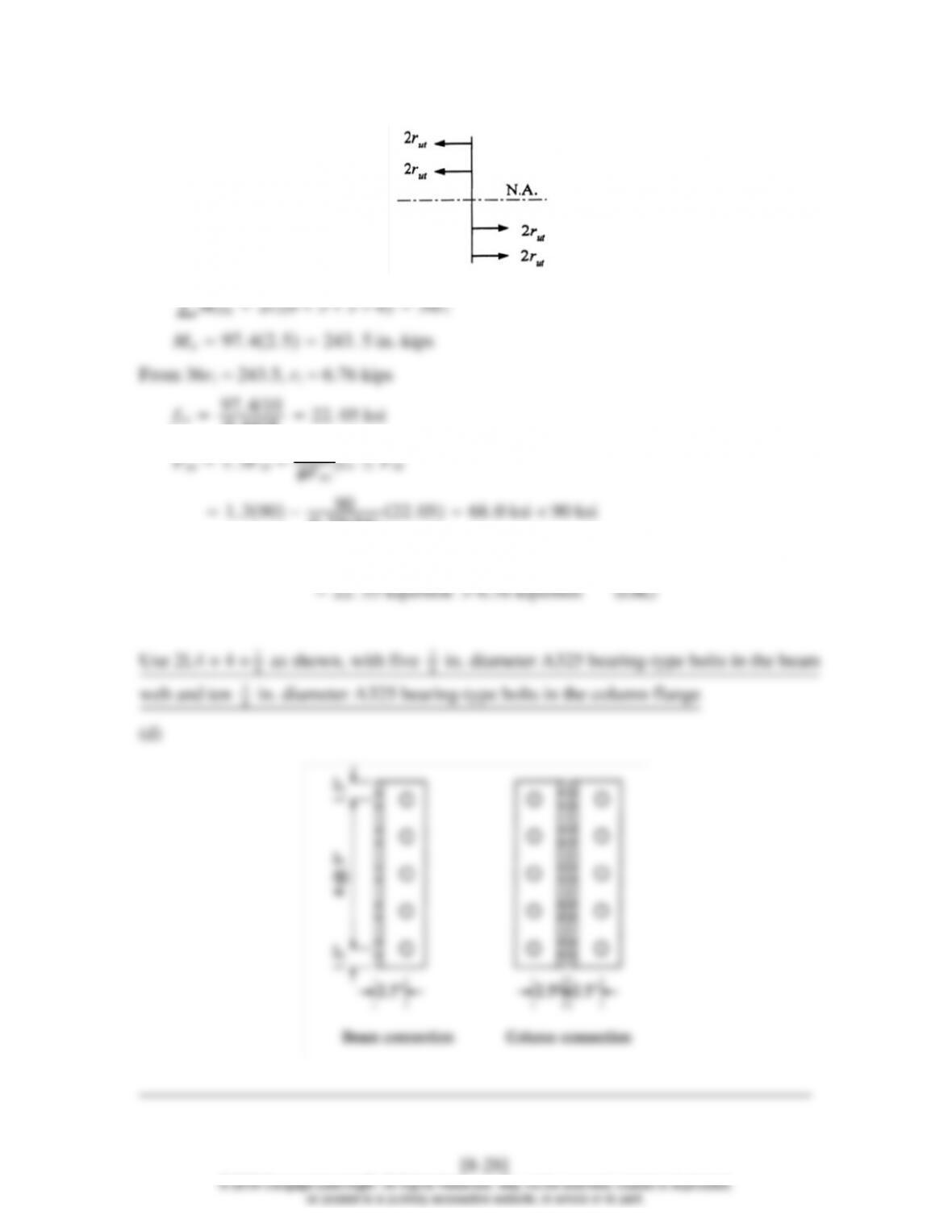
0. 4418 22. 05 ksi
′1. 3Fnt −Fnt
0. 755422. 0568. 0 ksi 90 ksi
RnFnt
′Ab0. 7568. 00. 4418
8.3–10
(a) Neglect the beam weight initially, and account for it later.
wa4kips/ft
Ma1
8waL21
84302450 ft-kips
Let 23. 86NbVa: 23. 86Nb61. 14 Nb2. 56
Try 4 bolts in beam-to-angle connection and 8 bolts in angle-to-column connection.
Use a minimum spacing of 3d33/42. 25 in.
Minimum edge distance from AISC Table J3.4 1in.
Try s3 in. and ℓe11
Let 388.4t Va 61. 14 t 0.157 in.
Check beam web. tw 0.440 in. There are no edge bolts. For the interior bolts,
Rn
1
1. 2LctFu1
2. 00 1. 22. 1880. 4406537. 55 kips/bolt
1
2. 4dtFu1
2. 00 2. 43/40. 4406525. 74 kips/bolt 37. 55 kips/bolt
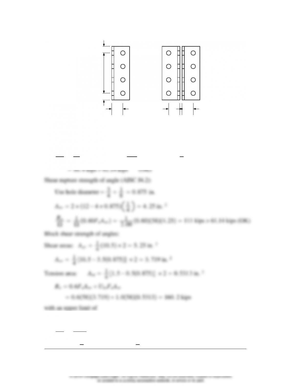
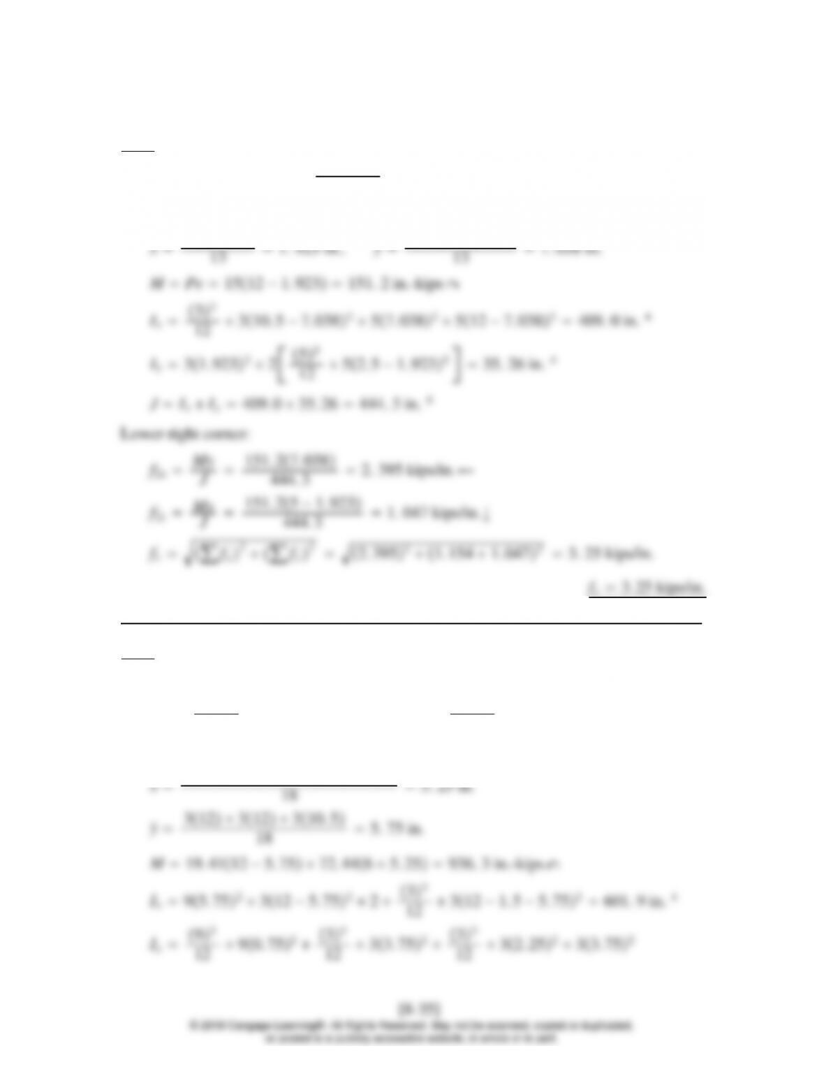
3 @ 3″
2.5″
1.5″1.5″
2.5″ 2.5″
Beam connection Column connection
Shear yield strength of angles (AISC J4.2):
Rn
1
0. 60FyAg21
1. 5 0. 603612 1
42
0. 6FyAgv UbsFuAnt 0. 6365. 251. 0580. 5313144. 2 kips
Rn
1
2. 00 144. 272. 1 kips 61. 14 kips (OK)
Use 2L4 41
4as shown, with four 3
4-in. diameter A325 bearing-type bolts in the
[8-31]
© 2018 Cengage Learning®. All Rights Reserved. May not be scanned, copied or duplicated,
or posted to a publicly accessible website, in whole or in part.
pmx My
∑x2y2152. 94. 5
45 15. 29 kips
p∑px2∑py215. 29215. 29221. 6 kips
Rn
1
FnvAb1
2. 00 540. 44182 shear planes
Upper right bolt is critical:
0. 4418 13. 84 ksi
Fnt
′1. 3Fnt −Fnt
Fnv
frv ≤Fnt
1. 390−2. 0090
(d)
8.4–1
Direct shearing stress: f1y9
780. 6 kips/in. ↓
Shearing stress caused by moment: Locate centroid with respect to upper left corner.
x
̄73. 5
̄84
8.4–2
Direct shearing stress: f1y15
5351. 154 kips/in. ↓
Shearing stress caused by moment: Locate centroid with respect to lower left corner.
8.4–3
Px75 cos 75 ° 19. 41 kips Py75 sin 75 ° 72. 44 kips ↓
f1x19. 41
18 1. 078 kips/in. f1y72. 44
18 4. 024 kips/in. ↓
Shearing stress caused by moment: Locate centroid with respect to lower left corner.
8.4–4
(a) LRFD solution:
Pu1. 2D1. 6L1. 22. 51. 67. 515. 0 kips
Load on one angle 15
27. 5 kips, fy7. 5
350. 5 kips/in. ↓
Since 4.59 kips/in. 4.18 kips/in., weld is not adequate.
(b) ASD solution:
Pa10 kips
Load on one angle 10
25kips, fy5
350. 333 3 kips/in. ↓
8.4–5
Locate centroid with respect to left side.
x
̄6432
18 4. 667 in.
Ix63
1. 392 5. 34 sixteenths.
For t1/2 in., min. w3/16 in. and max w1/2 −1/16 7/16 in.
Use a 3
8-in. fillet weld.
(b) ASD solution
0. 9279 5. 72 sixteenths.
8.4–6
(a) LRFD solution
DLD2D20 D6. 667 kips, L13. 33 kips
Pu1. 2D1. 6L1. 26. 6671. 613. 3329. 33 kips
f1y29. 33
f2xMy
J96. 793. 6
46. 42 7. 506 kips/in.
f2yMx
J96. 791. 3
46. 42 2. 711 kips/in. ↓
fv∑fx2∑fy27. 50625. 866 2. 711211. 4 kips/in.
M2021. 366. 0 in.-kips
12 31. 5 −1. 3223
12 20. 323. 217 in. 4
JIxIy43. 2 3. 217 46. 42 in. 4
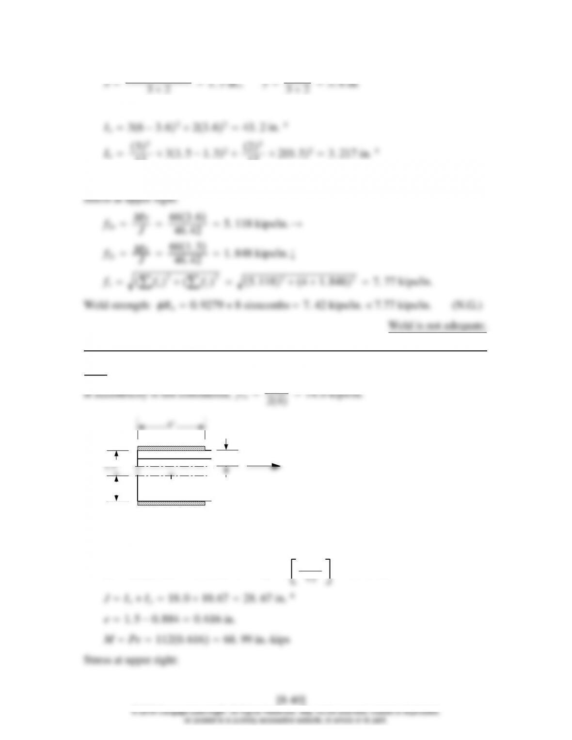
8.4–7
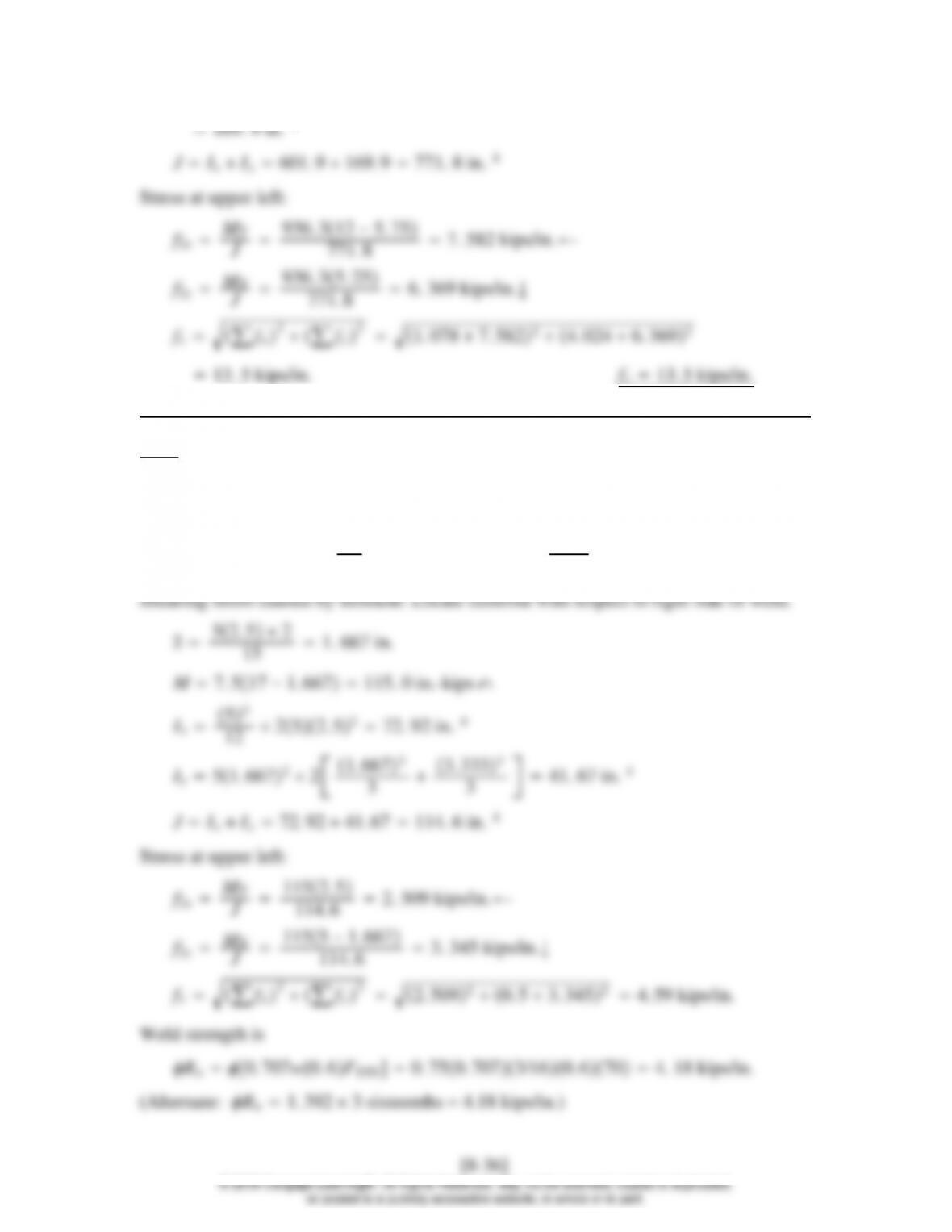
0.884″
1.5″
1.5″
4″
Load when eccentricity is considered:
Ix241. 5218. 0 in. 4,Iy243