modulus:
Ix1
12 twh32Af
htf
2
21
12 3/8733257. 573 2. 5
2
2
awhctw
bfctfc
733/8
232. 50. 476 1 10
From AISC Equation F5-6,
Rpg 1−aw
hc
−5. 7 E
≤1. 0
0. 7Fy
0. 750577. 9 in. 48.16 ft
[10-21]
48. 16 −14. 11 75. 49 50 ksi ∴use 50 ksi
MnRpgFcrSxc 0. 9796504513/12 1. 842 104ft-kips
bMn0. 90184201. 658 104ft-kips
Mu17000 ft-kips 16600 ft-kips (N.G.)
Try 2 1
cIx
h/2 tf183200
73/2 2. 54697 in.3
To compute the bending strength reduction factor Rpg, the value of awwill be needed:
awhctw
bfctfc
733/8
242. 50. 456 3 10
h
673
612. 17 in., I1
12 12. 173/831
12 2. 52432880 in.4
[10-22]
A242. 512. 173/864. 56 in.2,rtI
A2880
64. 56 6. 679 in.
Lb25. 0 ft
0. 7Fy
0. 750604. 0 in. 50.33 ft
Since LpLbLr, the girder is subject to inelastic lateral-torsional buckling. From
50. 33 −14. 74 76. 28 50 ksi ∴use 50 ksi
MnRpgFcrSxc 0. 9804504697/12 1. 919 104ft-kips
bMn0. 901. 919 1041. 727 104ft-kips
137. 3 73
137. 3 0. 531 7 in.
For a
≤12. 0 E
12. 0 29000
232. 0 73
232. 0 0. 314 7 in.
Try a 3
8in. 73 in. web.
h
73
2. 5 23. 52 in.
Try a 2. 5-in. 25-in. flange. Af252. 562. 5 in.2
Check web width-thickness ratio:
h
tw
194. 7, p3. 76 E
Fy
3. 76 29, 000
50 90. 55
r5. 70 E
5. 70 29000
cIx
h/2 tf190300
73/2 2. 54879 in.3
From AISC Equation F5-10, the tension flange strength based on yielding is
MnFySxt 5048792. 440 105in.-kips 20330 ft-kips
The compression flange strength is given by AISC Equation F5-7:
For flange local buckling, the relevant slenderness parameters are
bf
2tf
25
22. 55. 0 p0. 38 E
Fy
0. 38 29000
50 9. 152
Since p, the flange is compact and Fcr Fy50 ksi
[10-24]
0. 7Fy
0. 750630. 0 in. 52.5 ft
Since LpLbLr, the girder is subject to inelastic lateral-torsional buckling. From
52. 5 −15. 38 77. 01 50 ksi ∴use 50 ksi
MnRpgFcrSxc 0. 9811504879
10.7–3
Assume a girder weight of 160 lb/ft.
wu1. 2wD1. 6wL1. 20. 5 0. 1600. 792 kips/ft
Pu1. 6PL1. 6115184. 0 kips
137. 3 52
137. 3 0. 378 7 in.
From h
tw
≤12 E
Fy
12 29000
50 289. 0
and h
≤0. 40E
0. 4029000
tw
Cv1
1. 10 kvE
Fy
61. 22
1. 5 6. 419 in.
Try a 1 1
20. 63
13. 5 1. 528 10 (OK)
Girder weight 20. 63 213. 50. 490
144
0. 162 1 kips/ft ≈0.160 kips/ft (Say OK)
htf
21
2
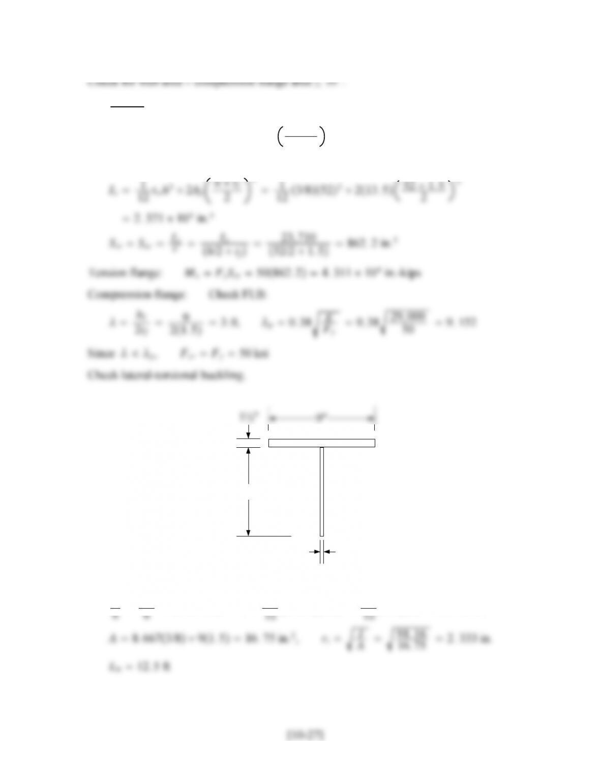
8.667″
3/8″
(not to scale)
h
0. 7Fy
0. 750211. 0 in. 17.58 ft
Since LpLbLr,
Lb−Lp
17. 58 −5. 15 41. 13 ksi 50 ksi
Af
13. 5 1. 528 10
Rpg 1−ar
1200 300ar
hc
tw
−5. 7 E
Fy
≤1. 0
10.7–4
(a) At the support, VuVLwuL
2Pu248
2120 168 kips
137. 3 46
137. 3 0. 335 in.
[10-28]
232. 0 46
232. 0 0. 198 3 in.
Try a 1
4in. 46 in. web.
h
tw
46
1/4 184. 0, Aw1/446 2212. 5 in.2
12 twh32Af
2
12 1/446321846 2
2
2. 276 104in.4
Sxt Sxc Ix
cIx
h/2 tf2. 276 104
46/2 2910. 4 in.3
0. 7Fy
0. 750223. 4 in. 18.62 ft
[10-29]
18. 62 −5. 453 37. 98 ksi (controls)
(Cb1. 0 is a conservative estimate.)
Compute the plate girder strength reduction factor.
Rpg 1−aw
hc
−5. 7 E
≤1. 0
Cv1
1. 10 kvE
Fy
h/tw
2h/tw2Fy
1. 10 kvE
1. 10 9. 59629000
Aw
12. 5 12. 8 ksi
h/tw184.
For vVn
12 ksi, a
15 ksi, a
Aw
8. 438 1. 896 ksi
For a
1. 10 5. 3429000
50 61. 22
Since h
tw
184. 0 61. 22,
10.7–5
From Problem 10.7-4, use a 1
446 web and 2 9 flanges. Reaction 168 kips
0. 56
E4
0. 56
29000 0. 296 6 in.
Try two plates, 5
16 in. 4 in., with 1-in. cutouts.
1. 8Fy
1. 8502. 489 in.2
From Apb 2b−1t,tApb/2b−12. 489
24−10. 414 8 in.
Try 7/16 4 plates.
2. 195 15. 72
Since Lc/r25, use Fcr Fy.
10.7–6
(a) wu1. 2wD1. 6wL1. 21. 01. 624. 4 kips/ft
Pu1. 6PL1. 6475760. 0 kips
Left reaction VLwuLPu
24. 480760
2556. 0 kips
htf
21
2
For a 1.5-in. length, Rn1. 513. 9220. 88 kips
Required spacing:
Rn
20. 88
sVuQ
Ix
13. 5 Vu2214
198000 Vu138. 3 kips
Shear at mid-span, left of load, 556 −4. 440380. 0 kips, so maximum spacing
will never be used.
Spacing required at mid-span RnIx
VuQ20. 88198000
38022144. 914 in.
Ix1
12 twh32Af
htf
2
12 0. 578322. 5 2278 2. 5
2
2
1. 980 105in.4
Use E70 electrodes, Rn/0. 9279Dkips/in., where Dweld size in sixteenths.
Try 5
16 -in. 11
2-in. intermittent fillet welds. For two welds,
Weld strength 20. 927959. 279 kips/in.
Base metal shear yield strength 0. 4tFy0. 40. 55010. 0 kips/in.
For a 1.5-in. length, Rn/1. 59. 27913. 92 kips
Required spacing:
Rn/
13. 92
sVaQ
Ix
13. 5 Va2214
198000 Va92. 21 kips
Shear at mid-span, left of load, 357. 5 −340237. 5 kips, so maximum spacing
will never be used.
10.7–7
(a) Assume a girder weight of 200 lb/ft.
wu1. 2wD1. 6wL1. 21. 3 0. 2001. 62. 35. 48 kips/ft
137. 3 77
137. 3 0. 560 8 in.
From h
≤12. 0 E
12. 0 29000
232. 0 77. 0
232. 0 0. 331 9 in.
tw
0. 5 154. 0, Aw0. 577 21. 540. 0 in.2
0. 9hFy
6544712
0. 97750−40. 0
612. 20 in. 2
bf≥12. 20
1. 5 8. 133 in.
Try a 1 1
2-in. 81
4-in. flange, Af1. 58. 2512. 38 in.2
Girder weight 40. 0 212. 380. 490
1. 5 8. 207 in.
Try a 1 1
2-in. 81
4-in. flange
Weight is the same as before: 0.2204 kips/ft 0.25 kips/ft assumed (OK)
Af1. 58. 2512. 38 in.2
htf
21
2
Compression flange: Compute the plate girder strength reduction factor.
Rpg 1−aw
1200 300aw
hc
tw
−5. 7 E
Fy
≤1. 0
awhctw
bfctfc
770. 5
8. 251. 53. 111 10
0. 7Fy
0. 750175. 0 in. 14.58 ft
Since LbLr,
Try a 0.5 77 web and a 1.5 14 flange. (Preliminary trials not shown.)
Af1. 51421. 0 in.2
htf
21
2
Rpg 1−1. 833
1200 3001. 833154 −5. 7 29000
50 0. 982 5 1. 0
Check FLB:
bf
2tf
14
21. 54. 667, p0. 38 E
Fy
0. 38 29, 000
50 9. 152
0. 7Fy
0. 750319. 9 in. 26.66 ft
Since LpLbLr,
Lb−Lp
26. 66 −7. 808 38. 71 ksi (controls)
(Cb1. 0 is a conservative estimate.)
MnRpgFcrSxc 0. 982538. 7120937. 96 104in.-kips
bMn0. 907. 96 104/12 5970 ft-kips