Min. longitudinal spacing 4d40. 52. 0 in.
Min. transverse spacing 4d40. 52. 0 in.
9.5–3
(a) Total load to be supported by the composite section (omit beam weight; check it
later):
Slab: 5
12. 5 85. 36 lb/ft.
For an 18-in. deep beam,
13. 5 79. 04 lb/ft.
Try a W18 86.
0. 85fc´ab AsFy
0. 854a841265, Solution is: a4. 429 in.
yd
2t−a
218. 4
25−4. 429
211. 99 in.
bMnbTy 0. 90126511. 99/12 1138 ft-kips 1067 ft-kips (OK)
Check beam weight:
80. 852230295. 9 ft-kips
bMnbMp698 ft-kips 95.9 ft-kips (OK) UseaW1886
(b) Total load to be supported by the composite section (omit beam weight; check it
later):
Slab: 5
13. 5 70. 45 ft-kips
Try a W18 76.
0. 854a841115, Solution is: a3. 904 in.
yd
2t−a
25
25−3. 904
25. 548 in.
Mn
1
Ty 1
0. 85fc´ab AsFy
0. 854a841265, Solution is: a4. 429in.
yd
2t−a
218. 4
25−4. 492
211. 95 in.
Mn
b
1
b
Ty 1
1. 67 126511. 95
Asa 5/82
40. 306 8 in.2,Ecwc
1.5 fc´1451.5 43492 ksi
′Ec≤RgRpAsaFu
Qn
14. 96 84. 56, round up to 85. total number 285170
Min. longitudinal spacing 4d45/82. 5 in.
Min. transverse spacing 4d45/82. 5 in.
Asa 3/42
40. 441 8 in.2,Ecwc
1.5 fc´1451.5 43492 ksi
′Ec≤RgRpAsaFu
Qn
21. 54 58. 73, round up to 59. total number 259118
For one stud at each section, the required spacing will be
9.6–1
(a) Before concrete cures:
Slab: 4
12 1507. 5375. 0 lb/ft
0. 85fc
′b
0. 854901. 06 in.
Area of transformed concrete C
Fy
324. 5
50 6. 49 in.2
[9-25]
© 2018 Cengage Learning®. All Rights Reserved. May not be scanned, copied or duplicated,
or posted to a publicly accessible website, in whole or in part.
Y2t−a
9.6–2
From Problem 9.2-2,
Beams are W18 97
t5in.
b84
384EIs
3842900017500. 214 4 in.
Δconst 5wconstL4
384EIs
50. 160/1230 124
3842900017505. 746 10−2in.
ΔΔ
DΔ
const 0. 2144 0. 05746 0. 271 9 in. Δ2. 63 in.
0. 85fc
′b
0. 854904. 657 in.
Y2t−a
25−4. 657
22. 672 in., dY218. 6 2. 672 21. 27 in.
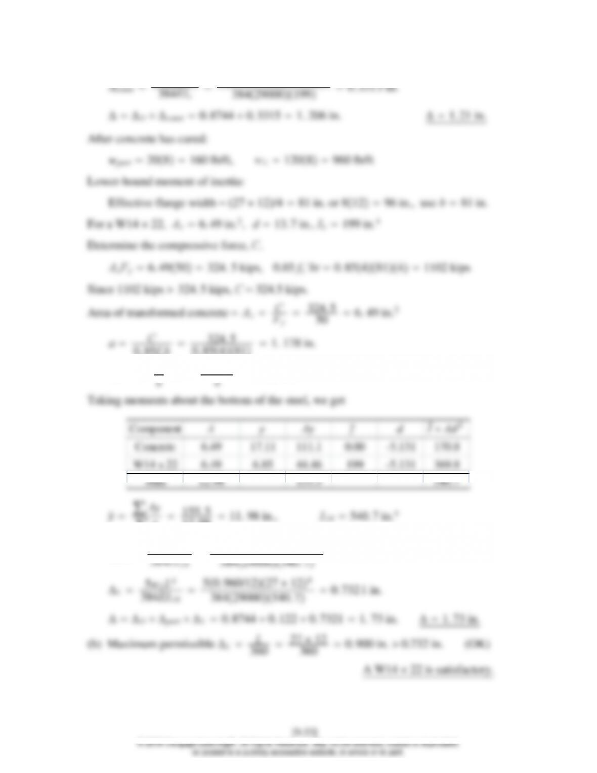
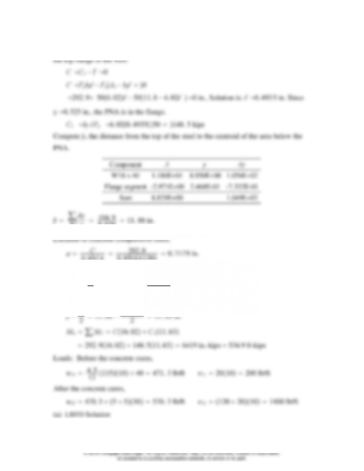
Taking moments about the bottom of the steel, we get
9.6–3
(a) From Problem 9.3-1, a W12 16 is used, with t4 in., s7ft,L25 ft,
qconst 20 psf, qpart 15 psf, qL125 psf, A992 steel and 4 ksi concrete.
Before concrete cures:
Slab: 4
∑A
9. 420 10. 76 in., ILB 316. 4 in.4
Δpart 5wpartL4
50. 105/1225 124
9.6–4
(a) From Problem 9.4-1, a W21 57 is used, with t6 in., s9ft,L40 ft,
qconst 20 psf, qL250 psf, A992 steel and 4 ksi concrete.
Before concrete cures:
Slab: 6
0. 85fc
′b
0. 8541082. 274 in.
Y2t−a
26−2. 274
24. 863 in.
Taking moments about the bottom of the steel, we get
[9-29]
© 2018 Cengage Learning®. All Rights Reserved. May not be scanned, copied or duplicated,
or posted to a publicly accessible website, in whole or in part.
0. 85fc´ab AsFy
0. 854a108810, Solution is: a2. 206in.
yd
2t−a
223. 6
26−2. 206
216. 70 in.
bMnbTy 0. 9081016. 701. 217 104in.-kips 1014 ft-kips
Loads:
[9-30]
© 2018 Cengage Learning®. All Rights Reserved. May not be scanned, copied or duplicated,
or posted to a publicly accessible website, in whole or in part.
wu1. 2wD1. 6wL1. 20. 7301. 60. 1801. 164 k/ft
Mu1
81. 164402233 ft-kips
bMnbMp503 ft-kips 233 ft-kips (OK)
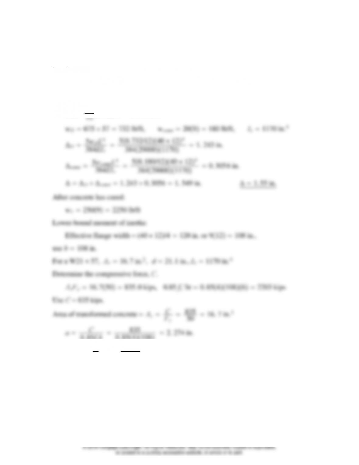
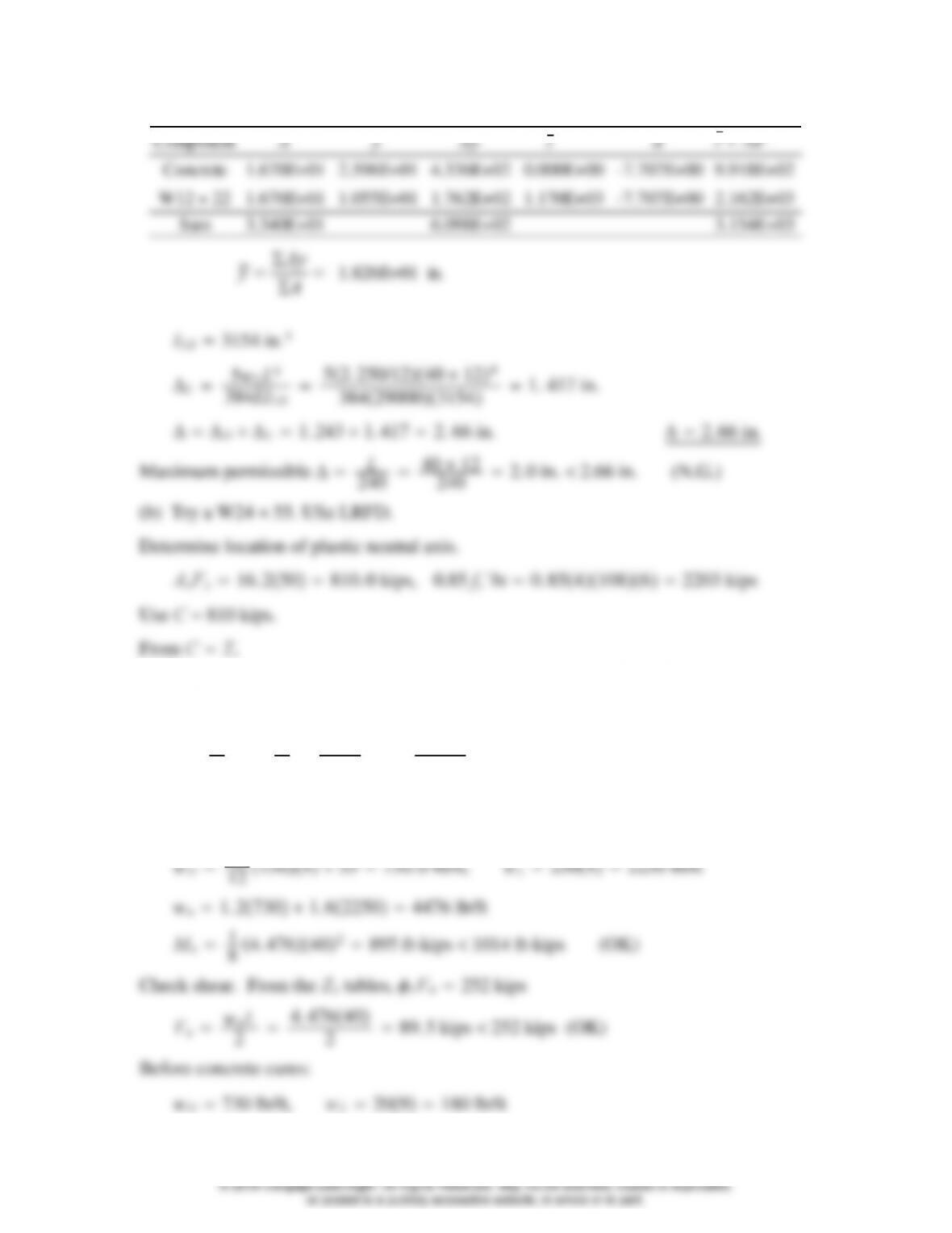
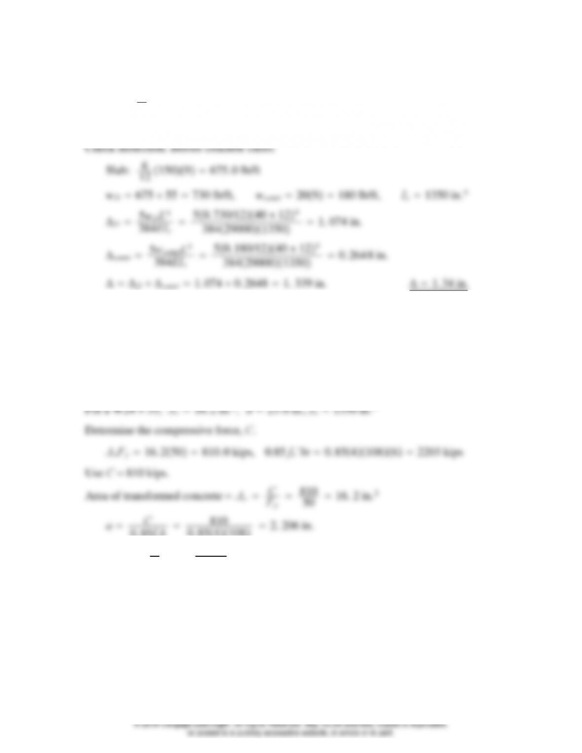
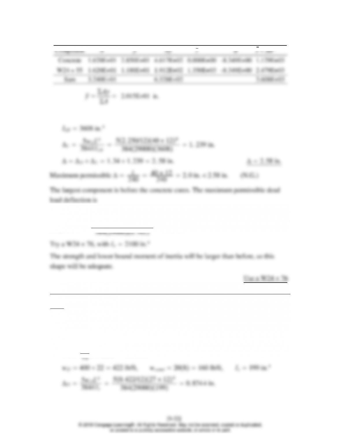
After concrete has cured:
wL25092250 lb/ft
Lower-bound moment of inertia:
Effective flange width (40 12/4 120 in. or 912108 in.
Use b108 in.
0. 85fc
′b
0. 8541082. 206 in.
Y2t−a
26−2. 206
24. 897 in.
Taking moments about the bottom of the steel, we get
[9-31]
© 2018 Cengage Learning®. All Rights Reserved. May not be scanned, copied or duplicated,
or posted to a publicly accessible website, in whole or in part.
2. 0 −1. 239 0. 761 in.
Required Is50. 730/1240 124
9.6–5
(a) From Problem 9.4-2, a W14 22 is used, with t4 in., s8ft,L27 ft,
qconst 20 psf, qpart 20 psf, qL120 psf, A992 steel and 4 ksi concrete.
Before concrete cures:
Slab: 4
0. 85fc
′b
0. 854811. 178 in.
Y2t−a
∑A
12. 98 11. 98 in., ILB 540. 7 in.4
Δpart 5wpartL4
50. 160/1227 124
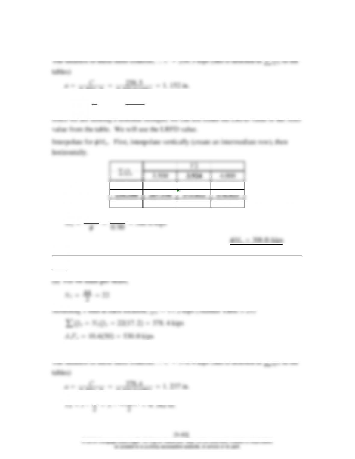
9.7–1
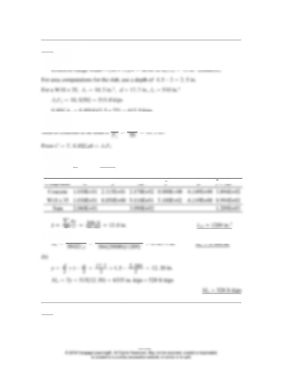
(a) Lower-bound moment of inertia:
0. 85fc
Use CV′515 kips.
From CT,0.85fc
0. 854a72515, Solution is: a2. 104 in.
Y2t−a
24. 5 −2. 104
23. 448 in.
∑A
20. 60 15. 0 in. ILB 1289 in.4
9.7–2
Steel headed stud anchors:
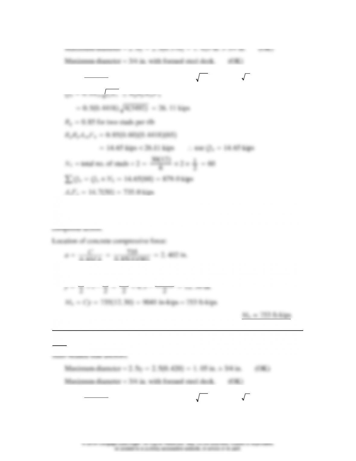
Asa 3/42
40. 441 8 in.2,Ecwc
1.5 fc´1451.5 43492 ksi
′Ec≤RgRpAsaFu
0.85 fc´bt 0. 854904. 5 −2765. 0 kips
Since AsFyis the smallest of the three possibilities, C735 kips, and there is full
0. 85fc
′b
0. 854902. 402 in.
Moment arm for concrete compressive force is
9.7–3
Asa 3/42
40. 441 8 in.2,Ecwc
1.5 fc´1451.5 43492 ksi
[9-35]
© 2018 Cengage Learning®. All Rights Reserved. May not be scanned, copied or duplicated,
or posted to a publicly accessible website, in whole or in part.
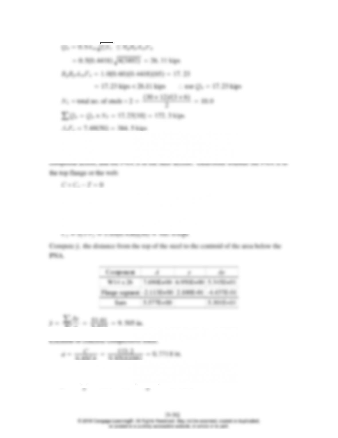
′Ec≤RgRpAsaFu
0.85 fc´bt 0. 854664. 5 −1. 5673. 2 kips
Since ∑Qnis the smallest of the three possibilities, C173.2 kips, there is partial
173. 2 Fybft′−FyAs−bft′0
173. 2 505. 03t′−507. 69 −5. 03t′0, Solution is: t′0. 420 1
Since tf0. 420 in., the PNA is at the bottom of the flange.
∑A
5. 577 9. 505 in.
0. 85fc
′b
0. 854660. 771 8 in.
Moment arm for concrete compressive force is
y
̄t−a
9.7–4
ThebeamisaW1840.
Asa 3/42
40. 441 8 in.2,Ecwc
1.5 fc´1451.5 43492 ksi
′Ec≤RgRpAsaFu
0.85 fc´bt 0. 8541204. 5 −1. 51224 kips
Since ∑Qnis the smallest of the three possibilities, C292.9 kips, there is partial
[9-37]
© 2018 Cengage Learning®. All Rights Reserved. May not be scanned, copied or duplicated,
or posted to a publicly accessible website, in whole or in part.
composite action, and the PNA is in the steel section. Determine whether the PNA is in
∑A
8. 829 11. 88 in.
0. 85fc
′b
0. 8541200. 717 9 in.
Moment arm for concrete compressive force is
y
̄t−a
211. 88 4. 5 −0. 7179
216. 02 in.
Moment arm for compressive force in the steel is
[9-38]
© 2018 Cengage Learning®. All Rights Reserved. May not be scanned, copied or duplicated,
or posted to a publicly accessible website, in whole or in part.
Before the concrete cures,
wu1. 20. 47131. 60. 2000. 885 6 kips/ft
Mu1
80. 8856402177 ft-kips
Ma1
80. 6713402134 ft-kips
Mnx
b
Mpx
b
196 ft-kips 134 ft-kips (OK)
After the concrete cures,
9.8–1
From the solution to Problem 9.7-3, for ¾-in. studs and fc´ 4ksi,Qn 17.23 kips
0.85 fc´bt 0. 854664. 5 −1. 5673. 2 kips
0. 85fc´b258. 5
0. 854661. 152 in.
Y2t−a
24. 5 −1. 152
23. 924 in.
9.8–2
0.85 fc´bt 0. 854905−2918. 0 kips
0. 85fc´b378. 4
0. 854901. 237 in.