with an upper limit of
The nominal block shear strength of the gusset plate is therefore 167.7 kips. The gusset
plate controls, and the nominal block shear strength of the connection is 167.7 kips
(a) Design strength for LRFD:
Block shear controls. Maximum factored load design strength 126 kips
(b) Allowable strength for ASD:
Block shear controls. Maximum service load allowable strength 83.9 kips
3.6–1
(a) Pu1. 2D1. 6L1. 2281. 684168 kips
Try L5 3½ ¾
[3-20]
© 2018 Cengage Learning®. All Rights Reserved. May not be scanned, copied or duplicated,
or posted to a publicly accessible website, in whole or in part.
Use an L5 3½ ¾
(b) PaDL28 84 112 kips
Try L5 3½ ¾
3.6–2
(a) Pu1. 2D1. 6L1. 21001. 650200. 0 kips
Try C12 25
(Although this value for the radius of gyration does not quite satisfy the AISC
recommendation for maximum slenderness, tensile strength is not affected by
slenderness, so some leeway is permitted. Therefore, we will consider this value
acceptable.)
[3-21]
© 2018 Cengage Learning®. All Rights Reserved. May not be scanned, copied or duplicated,
or posted to a publicly accessible website, in whole or in part.
(b) PaDL100 50 150 kips
Try C12 25
(Although this value for the radius of gyration does not quite satisfy the AISC
recommendation for maximum slenderness, tensile strength is not affected by
slenderness, so some leeway is permitted. Therefore, we will consider this value
acceptable.)
3.6–3
(a) Pu1. 2D1. 6L1. 2301. 690180. 0 kips
The angle leg must be at least 5 in. long to accommodate two lines of bolts (See
workable gages for angles, Manual Table 1-7A).
From AISC Table D4.1, for 4 or more bolts per line, U0. 80
(b) PaDL30 90 120 kips
The angle leg must be at least 5 in. long to accommodate two lines of bolts (See
workable gages for angles, Manual Table 1-7A).
From AISC Table D4.1, for 4 or more bolts per line, U0. 80
3.6–4
(a) Load combination 2 controls:
Try C10 20:
[3-23]
© 2018 Cengage Learning®. All Rights Reserved. May not be scanned, copied or duplicated,
or posted to a publicly accessible website, in whole or in part.
(b) Load combination 6 controls:
Try C12 25:
3.6–5
Try C10 20
3.6–6
[3-24]
© 2018 Cengage Learning®. All Rights Reserved. May not be scanned, copied or duplicated,
or posted to a publicly accessible website, in whole or in part.
Try W10 49
Ag14. 4 in.210. 9 in.2(OK)
3.7–1
(a) LRFD: Load combination 1 controls: Pu1. 44563. 00 kips
(b) ASD: Load combination 2 controls: PaDL45 550 kips
[3-25]
© 2018 Cengage Learning®. All Rights Reserved. May not be scanned, copied or duplicated,
or posted to a publicly accessible website, in whole or in part.
3.7–2
(a) Dead load beam weight 0.048 kips/ft
Because of symmetry, the tension is the same in both rods.
(b) Maximum force in rod occurs when live load is an A or D. Entire live load is
taken by one rod.
3.7–3
(a) Dead load beam weight 0.048 kips/ft
Because of symmetry, the tension is the same in both rods.
(b) Maximum force in rod occurs when live load is an A or D. Entire live load is
taken by one rod.
[3-26]
© 2018 Cengage Learning®. All Rights Reserved. May not be scanned, copied or duplicated,
or posted to a publicly accessible website, in whole or in part.
3.7–4
All members are pin-connected, and all loads are applied at the joints; therefore, all
members are two-force members (either tension members or compression members).
Load combination 4 controls.
At joint C,
3.7–5
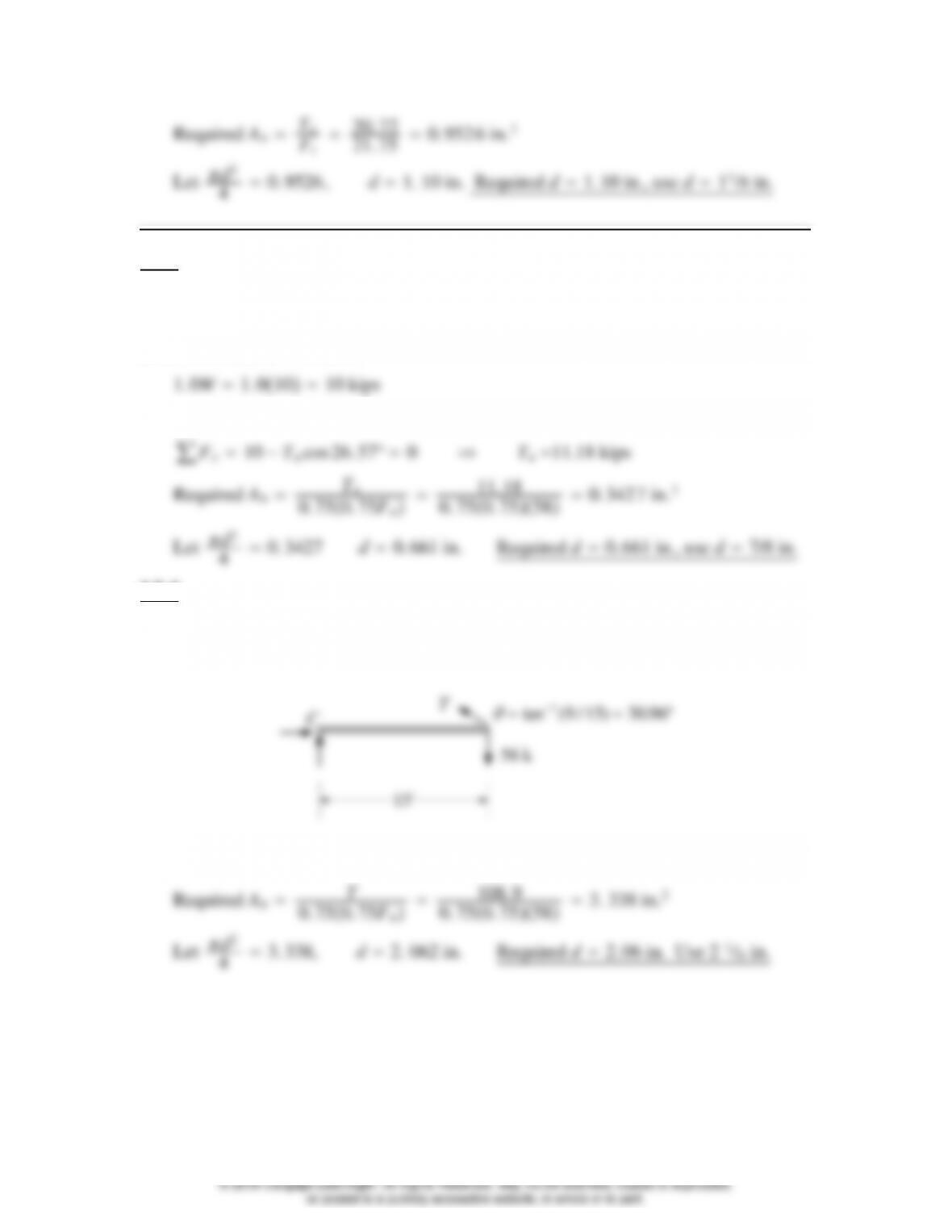
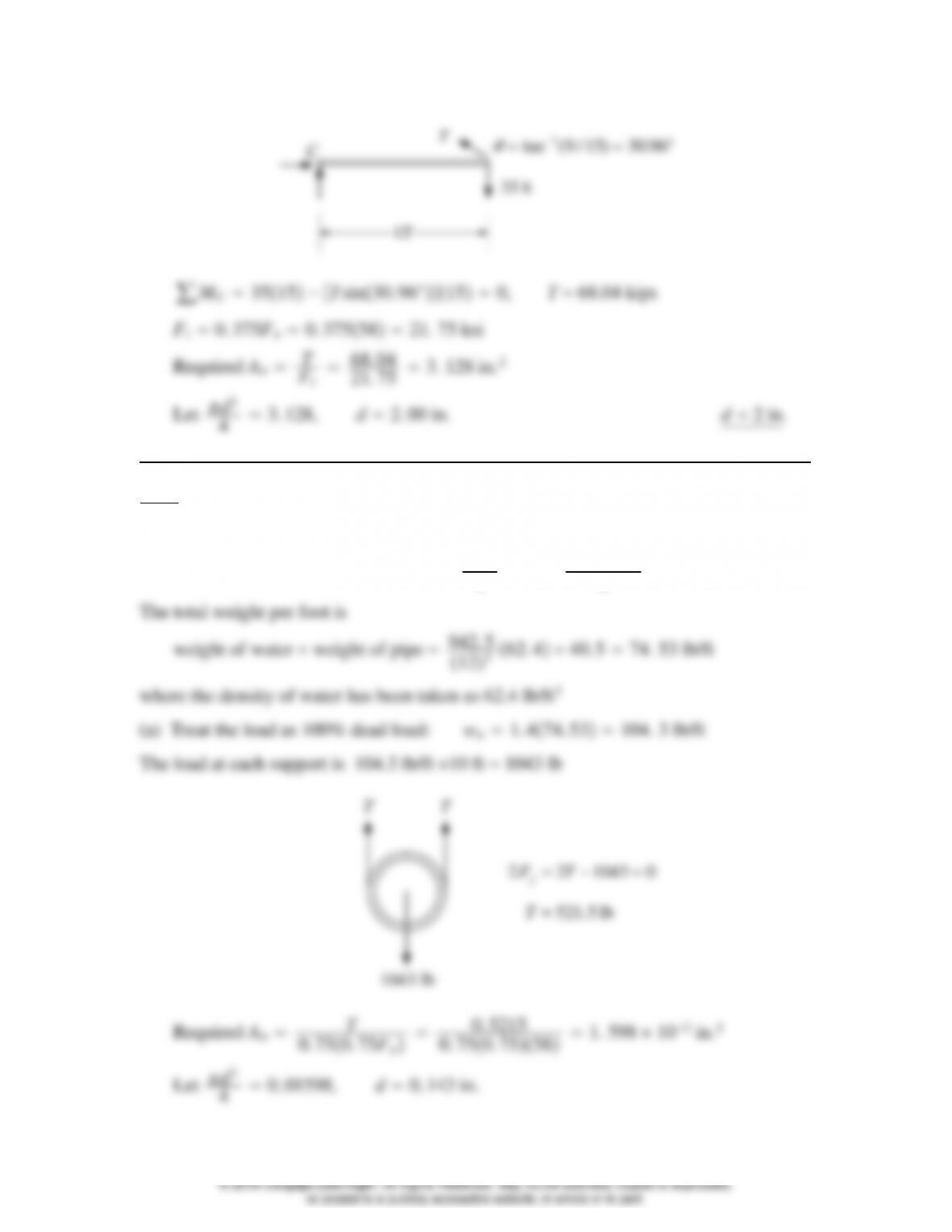
(a) LRFD: Pu1. 2D1. 6L1. 63556 kips
15′
T
56 k
C
tan ( / ) .
1915 3096
∑MC5615−Tsin30. 96°150, T108.9 kips
(b) ASD: PaDL35 kips
[3-27]
© 2018 Cengage Learning®. All Rights Reserved. May not be scanned, copied or duplicated,
or posted to a publicly accessible website, in whole or in part.
T
35 k
C
tan ( / ) .
1915 3096
3.7–6
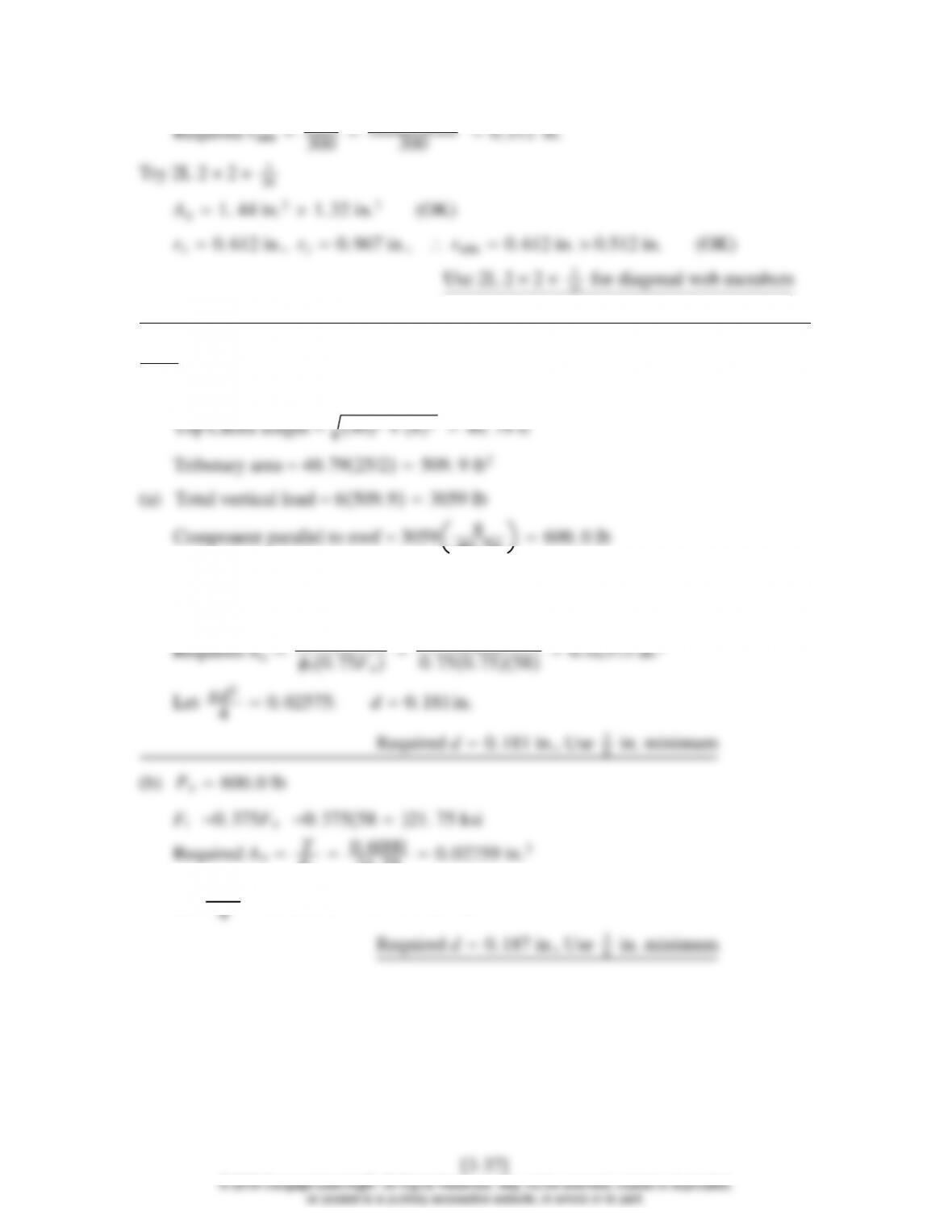
From Part 1 of the Manual, the inside diameter is d10. 0 in.
Volume of water per foot of length d2
412 10. 02
412 942. 5 in.3
[3-28]
© 2018 Cengage Learning®. All Rights Reserved. May not be scanned, copied or duplicated,
or posted to a publicly accessible website, in whole or in part.
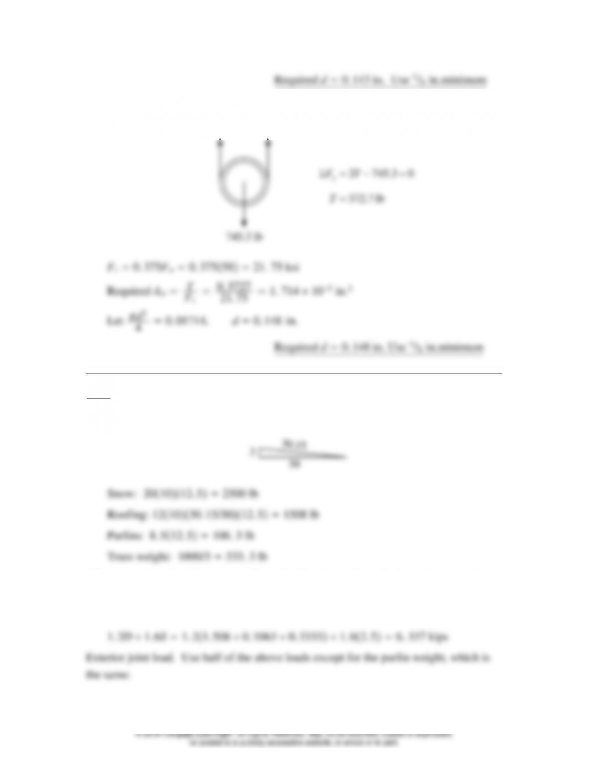
(b) The load at each support is 74.53 lb/ft 10 ft 745.3 lb.
TT
lb7.372
03.7452
T
TFy
3.8–1
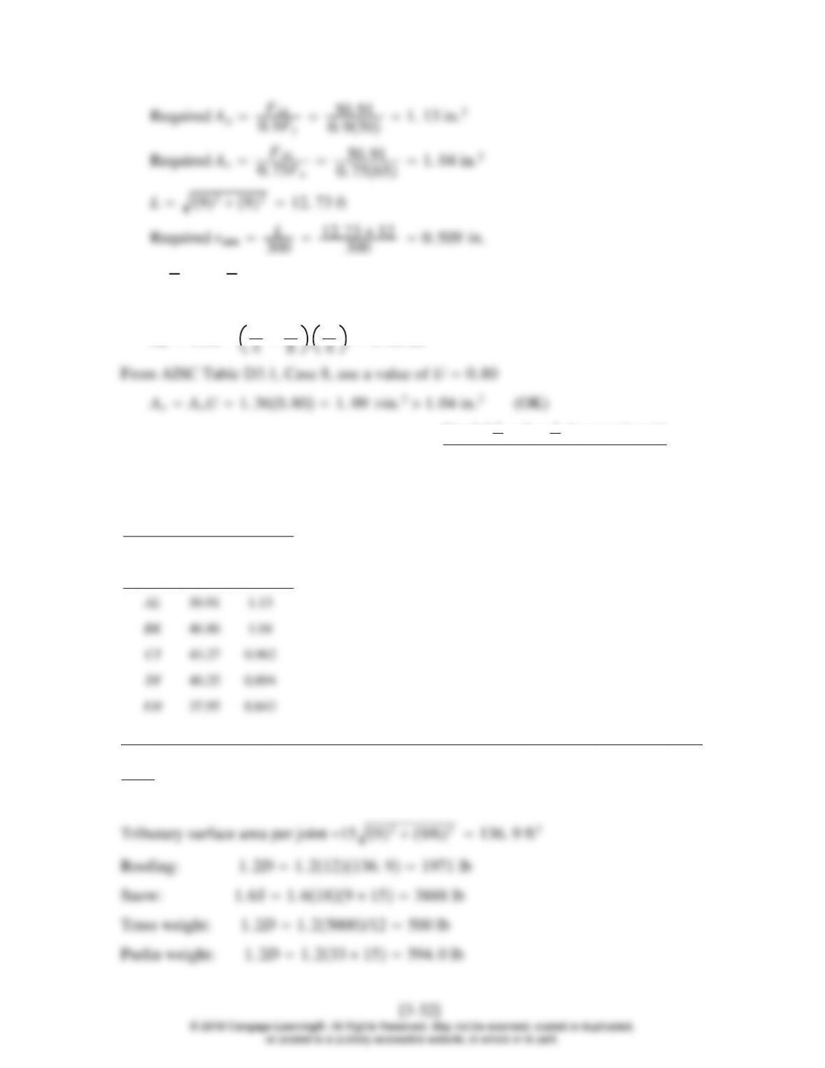
Interior joint load:
30.15
3
(The assumption that the truss weight is distributed equally to the joints is approximate
but is consistent with the approximate nature of the estimate of total truss weight.)
(a) Load combination 3 controls:
[3-29]
© 2018 Cengage Learning®. All Rights Reserved. May not be scanned, copied or duplicated,
or posted to a publicly accessible website, in whole or in part.
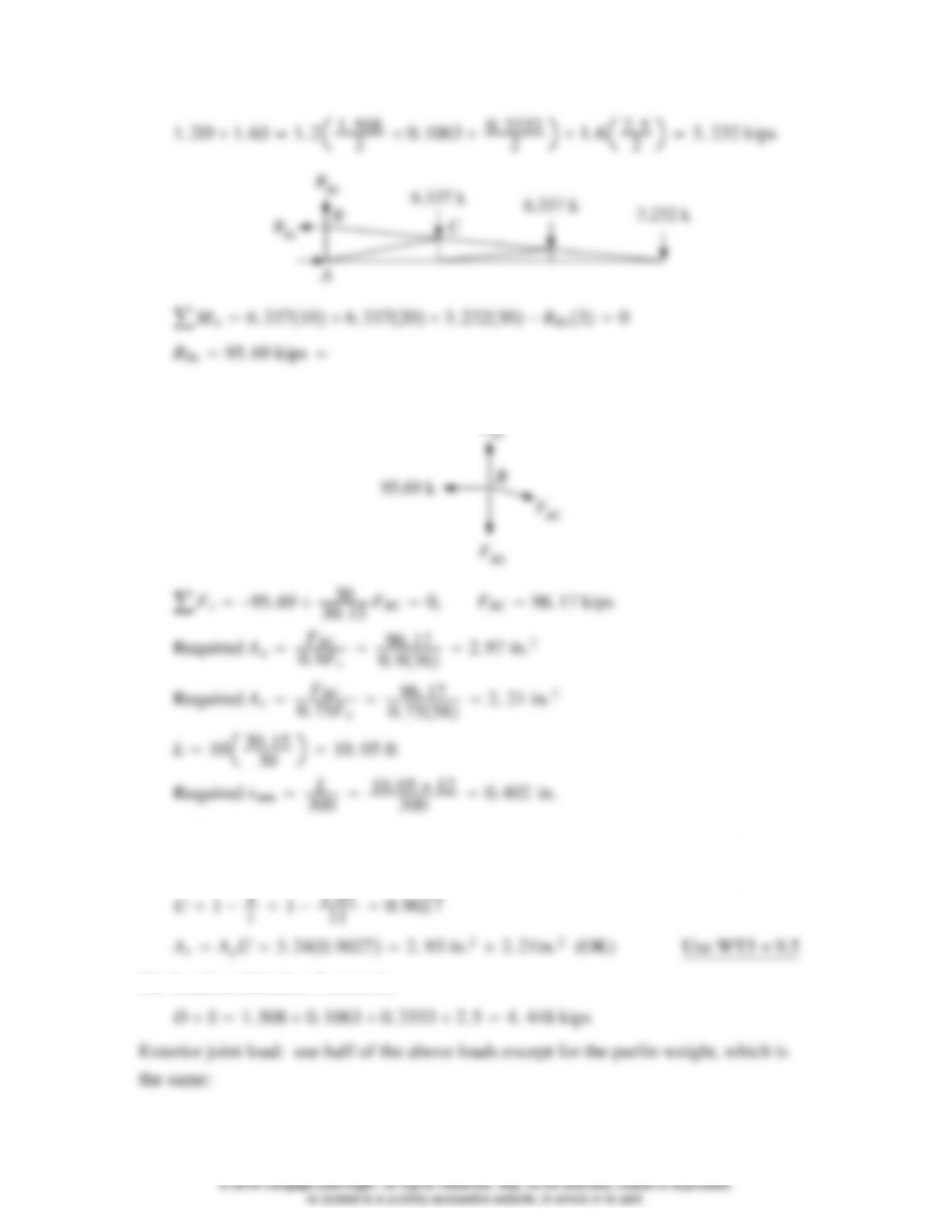
Joint B:
R
Try WT5 11
Ag3. 24 in.22. 79 in.2(OK) rmin 1. 33 in. 0.402 in. (OK)
̄
(b) Load combination 3 controls:
[3-30]
© 2018 Cengage Learning®. All Rights Reserved. May not be scanned, copied or duplicated,
or posted to a publicly accessible website, in whole or in part.
For a free-body diagram of the entire truss,
For a free body of joint B:
3.8–2
The diagonal web members are the tension members, and member AL has the largest
force.
[3-31]
© 2018 Cengage Learning®. All Rights Reserved. May not be scanned, copied or duplicated,
or posted to a publicly accessible website, in whole or in part.
Try L3 1
231
4
Ag1. 58 in.21. 13 in.2(OK) rmin 0. 628 in. 0.509 in. (OK)
An1. 58 −3
1
Use L3 1
231
4for member AL
This shape can be used for all of the web tension members. Although each member
could be a different size, this would not usually be practical. The following table
shows the relatively small difference in requirements for all the web tension members.
Force Req’d Ag
Member (kips) (in.2
3.8–3
Use load combination 3: 1. 2D1. 6S.
[3-33]
© 2018 Cengage Learning®. All Rights Reserved. May not be scanned, copied or duplicated,
or posted to a publicly accessible website, in whole or in part.
3.8–4
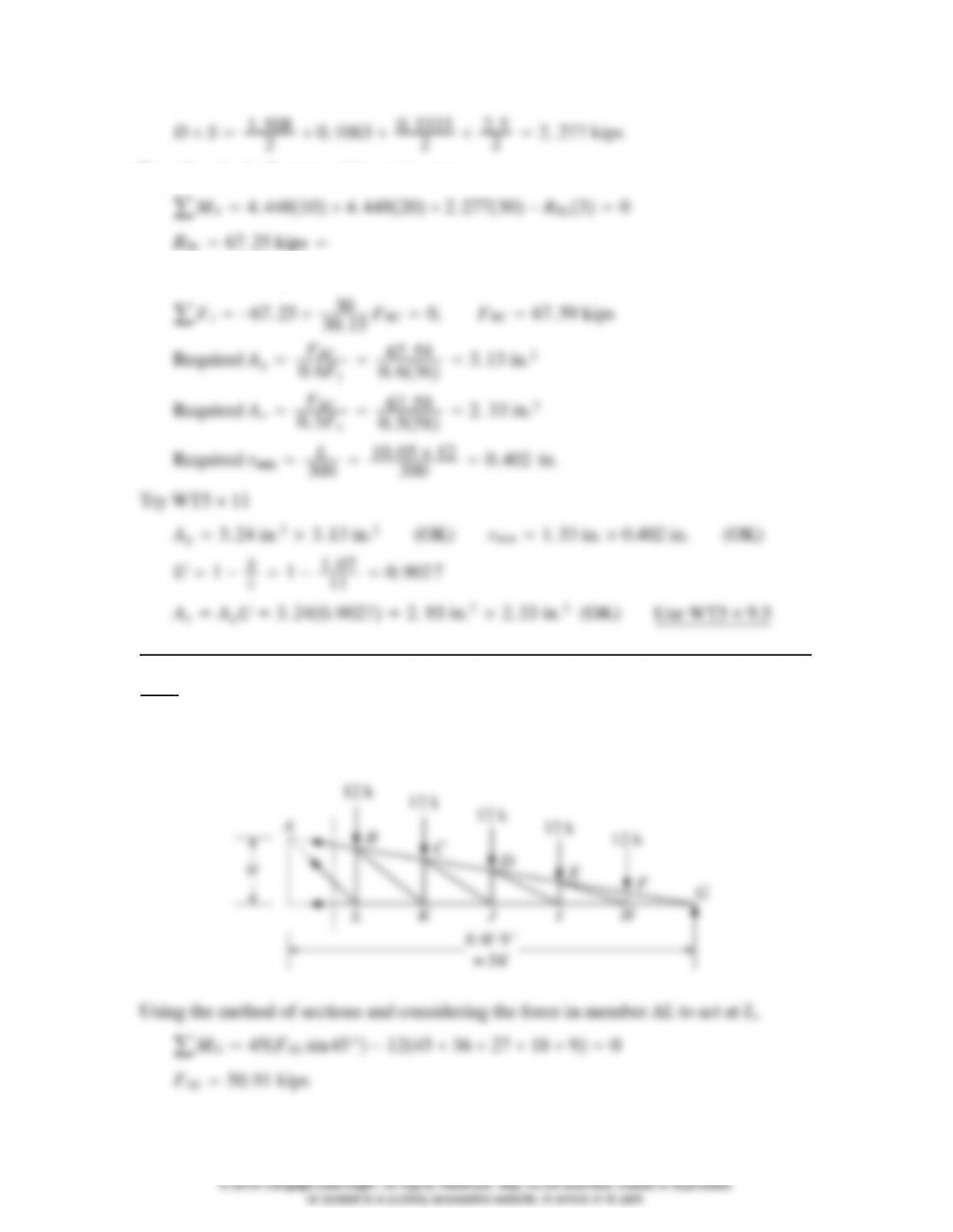
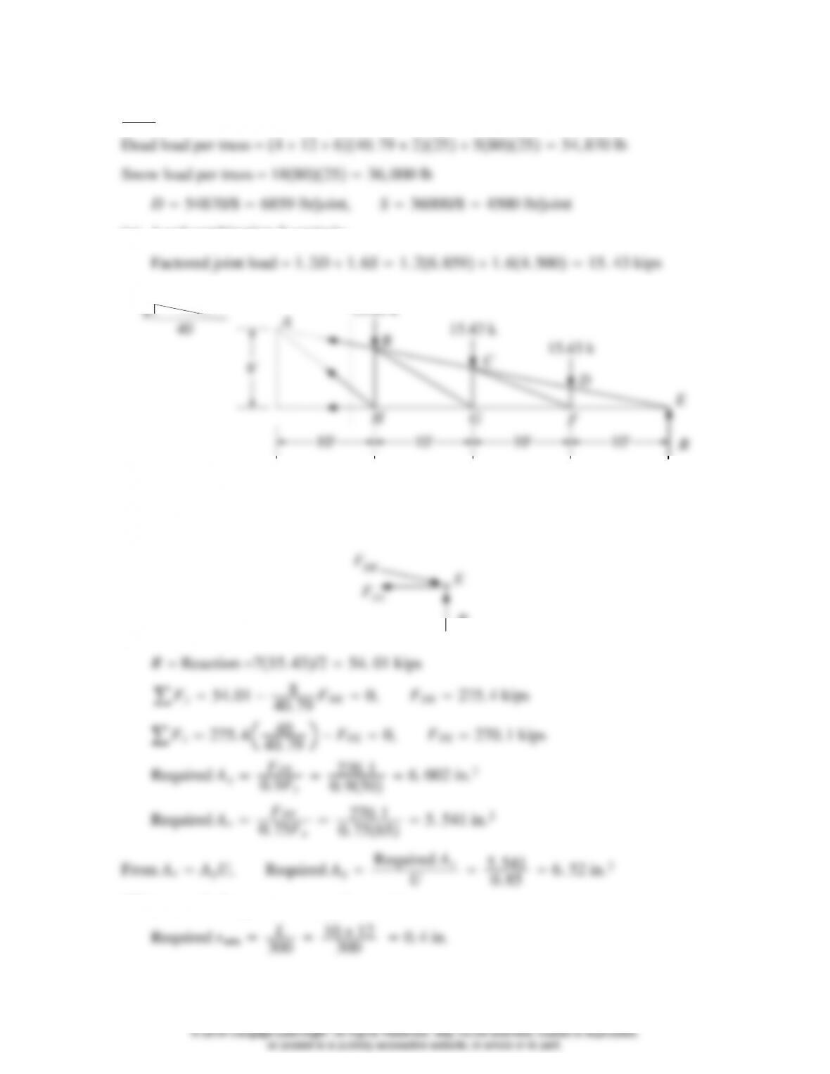
(a) Load combination 3 controls:
8′
10′ 10′ 10′ 10′
R
C
D
E
F
GH
Bottom chord: Member FE has the largest tension force.
Use a free body of joint E:
(This controls the gross area requirement.)
[3-34]
© 2018 Cengage Learning®. All Rights Reserved. May not be scanned, copied or duplicated,
or posted to a publicly accessible website, in whole or in part.
Web members: Design for the maximum tensile force, which occurs in member AH,
and use one shape for all tension web members (the diagonal web members). Using the
method of sections (see figure), consider the force in member AH to act at H.
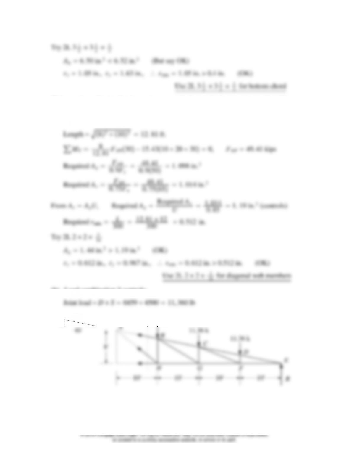
(b) Load combination 3 controls:
10′ 10′ 10′ 10′
R
Bottom chord: Member FE has the largest tension force.
[3-35]
© 2018 Cengage Learning®. All Rights Reserved. May not be scanned, copied or duplicated,
or posted to a publicly accessible website, in whole or in part.
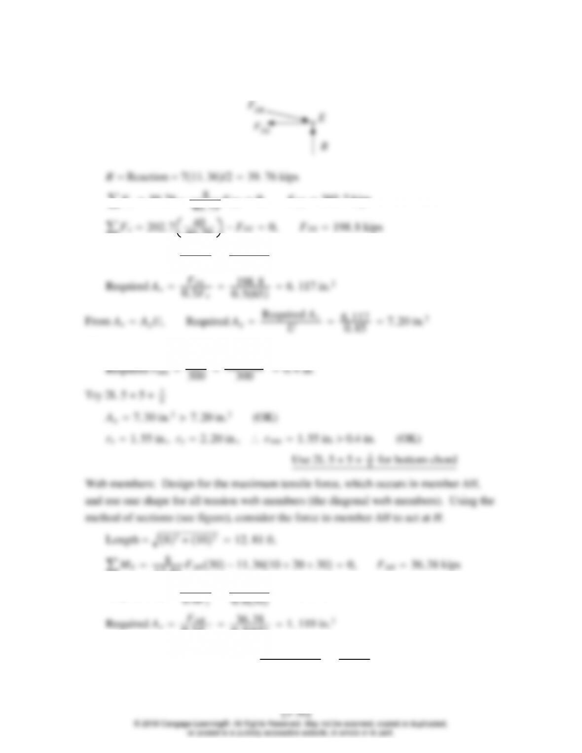
Use a free body of joint E:
F
DE
E
F
FE
∑Fy39. 76 −8
40. 79 −FFE 0, FFE 198. 8 kips
Required AgFFE
0. 6Fy
198. 8
0. 6506. 627 in.2
(This controls the gross area requirement.)
12. 81 FAH30−11. 3610 20 300, FAH 36. 38 kips
Required AgFAH
36. 38
0. 5Fu
0. 5651. 119 in.2
From AeAgU, Required AgRequired Ae
U1. 119
0. 85 1. 32 in.2(controls)
3.8–5
Use sag rods at midspan of purlins.
40. 79 600. 0 lb
Since the design is for dead load only, use load combination 1:
Pu1. 4D1. 4600840 lb
Ft
21. 75 0. 02759 in.2
Let d2