Unlock document.
This document is partially blurred.
Unlock all pages and 1 million more documents.
Get Access
CHAPTER 10 -PLATE GIRDERS
10.4-1
5. 70 29, 000
50 137. 3
Since 3. 76 E
Fy
h
tw
5. 70 E
Fy
, the web is noncompact, and the provisions of
AISC F4 apply. However, the slender-web provisions of AISC F5 may be used (see
User Note in AISC F4).
Because the girder has continuous lateral support, lateral-torsional buckling does not
apply.
10.4-2
tw
0. 5 140. 0 5. 70 E
Fy
Fy
50 137. 3
Since h
tw
5. 70 E
Fy
, this is a slender-web shape (plate girder).
htf
21
2
10.4-3
h
tw
60
3/8 160, 5. 70 E
Fy
5. 70 29, 000
50 137. 3
Since h
tw
5. 70 E
Fy
, the web is slender.
htf
21
2
2tf
27/86. 857 p0. 38 E
Fy
50 9. 152
∴Fcr Fy50 ksi
Rpg 1−aw
1200 300aw
hc
tw
−5. 7 E
Fy
≤1. 0
awAw
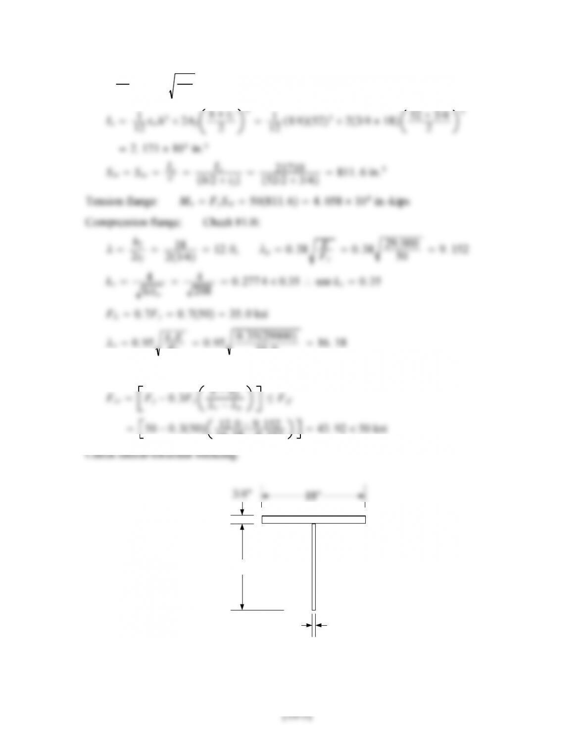
603/8
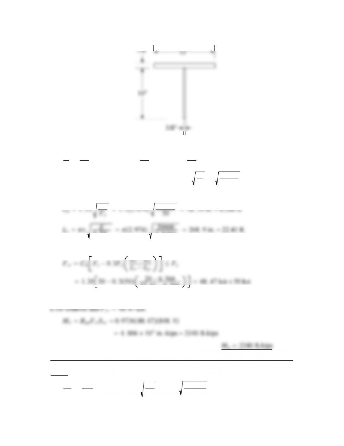
(not to scale)
h
660
610 in., I1
12 103/831
12 7/8123126. 0 in.4
A103/8127/814. 25 in.2,rtI
A126
14. 25 2. 974 in.
Lb40/2 20 ft
0. 7Fy
0. 750268. 9 in. 22.41 ft.
Since LpLbLr,
Lb−Lp
22. 41 −6. 566 48. 47 ksi 50 ksi
where Cb1. 30 is from Figure 5.15 in the textbook.
10.4-4
h
tw
52
1/4 208, 5. 70 E
Fy
5. 70 29, 000
50 137. 3
[10-4]
Since h
tw
5. 70 E
Fy
, the web is slender.
htf
21
2
FL
35. 0 16. 18
Since pr,
−p
16. 18 −9. 152 43. 92 50 ksi
8.667"
1/4"
(not to scale)
h
0. 7Fy
0. 750436. 1 in. 36.34 ft.
Since LpLbLr,
Lb−Lp
36. 34 −10. 65 54. 11 ksi 50 ksi
where Cb1. 30 is from Figure 5.15 in the textbook. Since Fcr Fy,use
Fcr Fy50 ksi
FLB controls and Fcr 42. 94 ksi. Compute the plate girder strength reduction factor.
10.4-5
Since h
tw
5. 70 E
Fy
, the web is slender.
htf
21
2
2tf
22. 54. 4 p0. 38 E
Fy
50 9. 152
∴Fcr Fy50 ksi
Rpg 1−ar
1200 300ar
hc
tw
−5. 70 E
Fy
≤1. 0
awAw
780. 5
8wuL2PuL
41
84. 480276080
41. 872 104ft-kips
Since 18,700 ft-kips 17,700 ft-kips, flexural strength is not adequate
(b) ASD solution
Mn
b
1. 969 104
1. 67 1. 179 104ft-kips
10.5-1
(a) h
70
1. 10 kvE
1. 10 1029000
Cv1
1. 10 kvE
Fy
h/tw
83. 77
140 0. 598 4
1. 10 kvE
Fy
1. 10 5. 61329000
50 62. 76
Since h
tw
62. 76, use AISC Equation G2-7 or G2-8
1. 15 1 a/h2
Compute Cv2.1.37
kvE
1. 37 5. 61329000
1. 15 1 2. 8572
Check the no-tension field case:
1. 10 kvE
Fy
62. 76
Since h/tw62. 76,
Cv1
1. 10 kvE
Fy
h/tw
62. 76
140 0. 448 3
Since h
61. 22, Cv1
1. 10 kvE
Fy
61. 22
10.5-2
(a) h
90
0. 90 533. 3 kips
Aw90 119/1651. 75 in.2
Vn0. 6AwFyCv10. 651. 7550Cv1533. 3, Solution is: Cv10. 343 5
1. 10 kvE
Fy
1. 10 5. 3429000
50 61. 22
Since h
tw
61. 22, Cv1
1. 10 kvE
Fy
h/tw
61. 22
160 0. 382 6
Vn0. 6FyAwCv10. 65051. 750. 3826594. 0 kips 533.3 kips
No intermediate stifferers are required.
Since h
61. 22, Cv1
1. 10 kvE
Fy
61. 22
10.5-3
Before developing the LRFD and ASD solutions, compute the nominal shear strength
of each panel.
h
66
1. 10 kvE
Fy
1. 10 8. 97929000
50 79. 38
Since h
tw
79. 38, Cv1
1. 10 kvE
Fy
h/tw
79. 38
211. 2 0. 375 9
1. 10 kvE
Fy
1. 10 8. 49029000
50 77. 19
[10-11]
1. 15 1 a/h2
Compute Cv2.1.37
kvE
1. 37 8. 49029000
1. 10 kvE
1. 10 5. 3429000
tw
Cv1
1. 10 kvE
Fy
h/tw
61. 22
211. 2 0. 289 9
Vn0. 6FyAwCv10. 65021. 560. 2899187. 5 kips
(a) LRFD solution
51. 2 kips 169 kips (OK)
Girder has enough shear strength
(b) ASD solution
End panel: Allowable strength Vn
v
243. 1
1. 67 146 kips
10.5-4
1. 10 kvE
1. 10 18. 229, 000
tw
Cv1
1. 10 kvE
Fy
h/tw
113
156 0. 724 4
1. 10 kvE
Fyw
1. 10 6. 46729000
50 67. 37
Since h
tw
67. 37, use AISC Equation G2-7 or G2-8
1. 15 1 a/h2
Compute Cv2.1.37
kvE
1. 37 6. 46729000
1. 15 1 1. 8462
(a) Compute the factored-load shear at the beginning of each panel (this will be the
maximum shear in the panel).
wu1. 2wD1. 6wL1. 21. 01. 624. 4 kips/ft
Pu1. 6PL1. 6475760. 0 kips
The shear strength of all of the 12-ft panels will be the same, and the shear is less than
617 kips in each 12-ft panel. Therefore, there will be enough shear strength in all of the
12-ft panels.
The girder has enough shear strength.
(b) Compute the required strength at the beginning of each panel (this will be the
v
1. 67 540 kips 358 kips (OK)
First interior panel:
Allowable strength Vn
v
685. 4
1. 67 410 kips 346 kips (OK)
[10-15]
10.6-1
Bearing strength: Apb 6−0. 51/225. 5 in.2
3. 036 13. 83
From AISC J4.4, for compression elements with Lc/r25, the nominal strength is
RnFyAg368. 442303. 9 kips
10.6-2
Bearing strength: Apb 6−0. 59/16412. 38 in.2
Compressive strength: The maximum permissible length of web is
3. 492 7. 732
From AISC J4.4, for compression elements with Lc/r25, the nominal strength is
RnFyAg5013. 92696. 0 kips
10.7-1
Try tf¾ in., h73 −20. 7571. 5 in.
h
≥5. 70 E
5. 70 29, 000
∴tw≤h
137. 3 71. 5
137. 3 0. 520 8 in.
From h
≤11. 7 E
11. 7 29, 000
241. 4 71. 5
241. 4 0. 296 2 in.
Try a 5
0. 9hFy
6360012
0. 971. 550−22. 34
69. 703 in. 2
bf≥9. 703
0. 75 12. 94 in.
Try a 3
4-in. 14-in. flange, Af0. 751410. 5 in.2
htf
21
2
2
19. 24 −9. 152 49. 55 ksi
Af
10. 5 2. 128 10
RPG 1−ar
1200 300ar
hc
tw
−5. 70 E
Fcr
≤1. 0
1−2. 128
1200 3002. 128228. 8 −5. 70 29, 000
49. 55 0. 894 8 1. 0
SxIx
cIx
h/2 tf43, 790
71. 5/2 0. 751200 in.3
Tension flange: MnSxReFyf 12001. 0506. 0 104in.-kips
Compression flange: Check FLB:
2
r−p
1. 0501−1
2
11. 67 −9. 152
19. 24 −9. 152 43. 76 ksi
Af
13. 13 1. 701 10
RPG 1−ar
1200 300ar
hc
tw
−5. 70 E
Fcr
≤1. 0
10.7-2
(a) Try tf2.5 in., h78 −22. 573. 0 in.
137. 3 73
137. 3 0. 531 7 in.
For a
≤12. 0 E
12. 0 29000
232. 0 73
232. 0 0. 314 7 in.
Try a 3
8in. 73 in. web.
h
73
Try a 2. 5-in. 23-in. flange. Af232. 557. 5 in.2
Check web width-thickness ratio:


