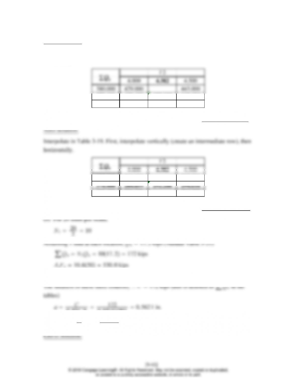
LRFD Solution:
Interpolate in Table 3-19. First, interpolate vertically (create an intermediate row), then
horizontally.
378.400 428.488 439.135 442.424
305.000 405.000 416.000
bMn439 ft-kips
380.000 285.000 295.000
305.000 269.000 277.000
Rn/b292 ft-kips
0.85 fc´bt 0. 854905−2918. 0 kips
0. 85fc´b172
0. 854900. 562 1 in.
Y2t−a
25−0. 5621
24. 719 in
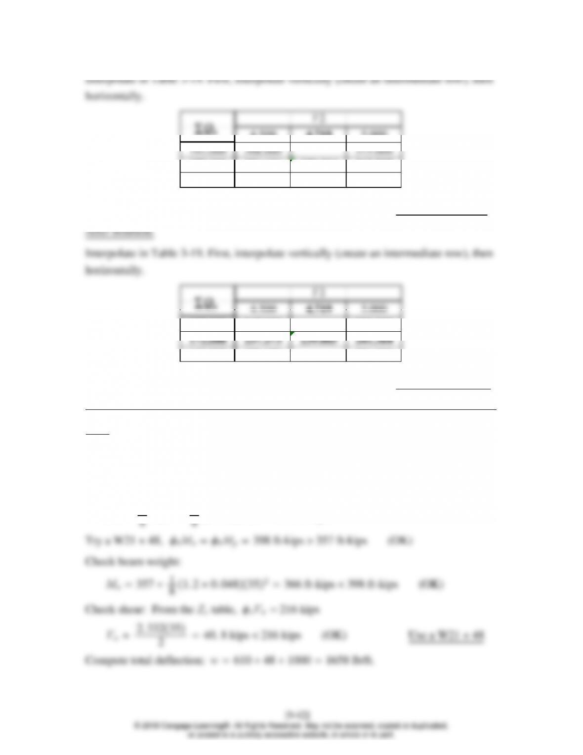
4.500 4.719 5.000
172.000 356.636 359.304 362.727
148.000 343.000 348.000
bMn359 ft-kips
192.000 245.000 250.000
148.000 228.000 231.000
Rn/b239 ft-kips
9.8–3
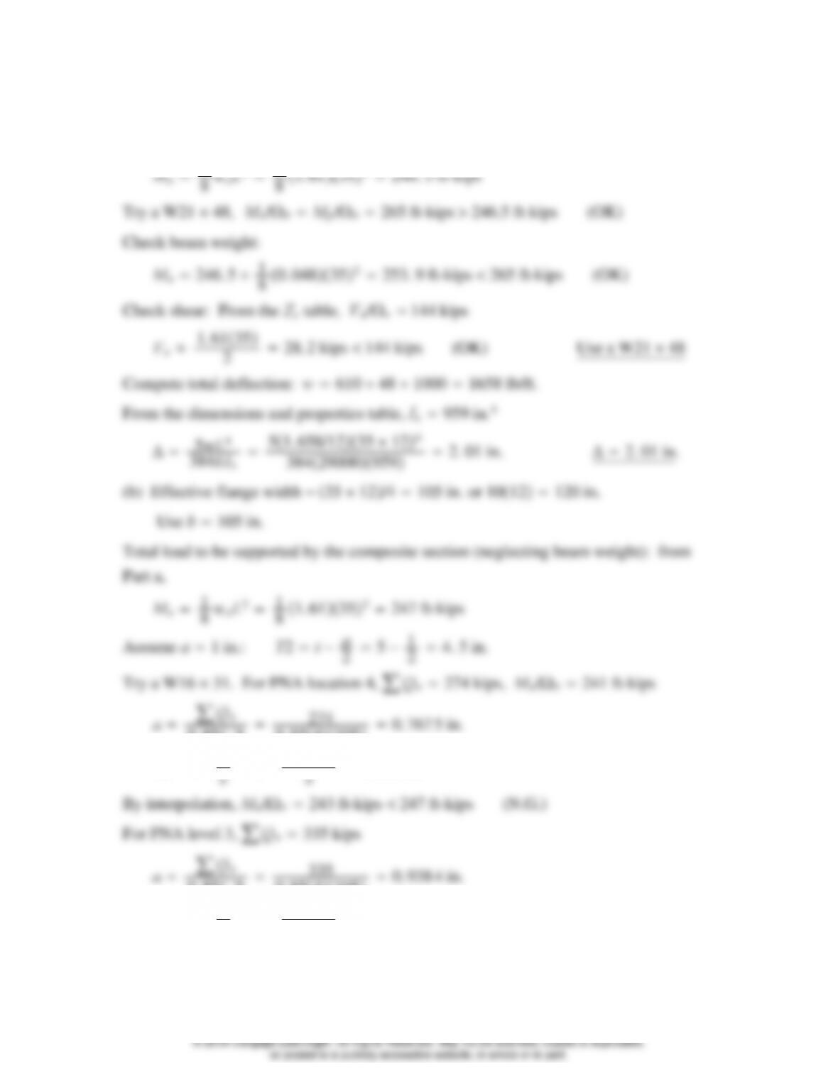
(a) wD51 1010610 lb/ft (neglect beam wt. and check it later.)
wL80 20101000 lb/ft
wu1. 2wD1. 6wL1. 20. 6101. 61. 0002. 332 lb/ft
Mu1
0. 85fc´b274
0. 8541050. 767 5 in.
Y2t−a
25−0. 7675
24. 616 in.
By interpolation, bMn365 ft-kips 357 ft-kips (OK)
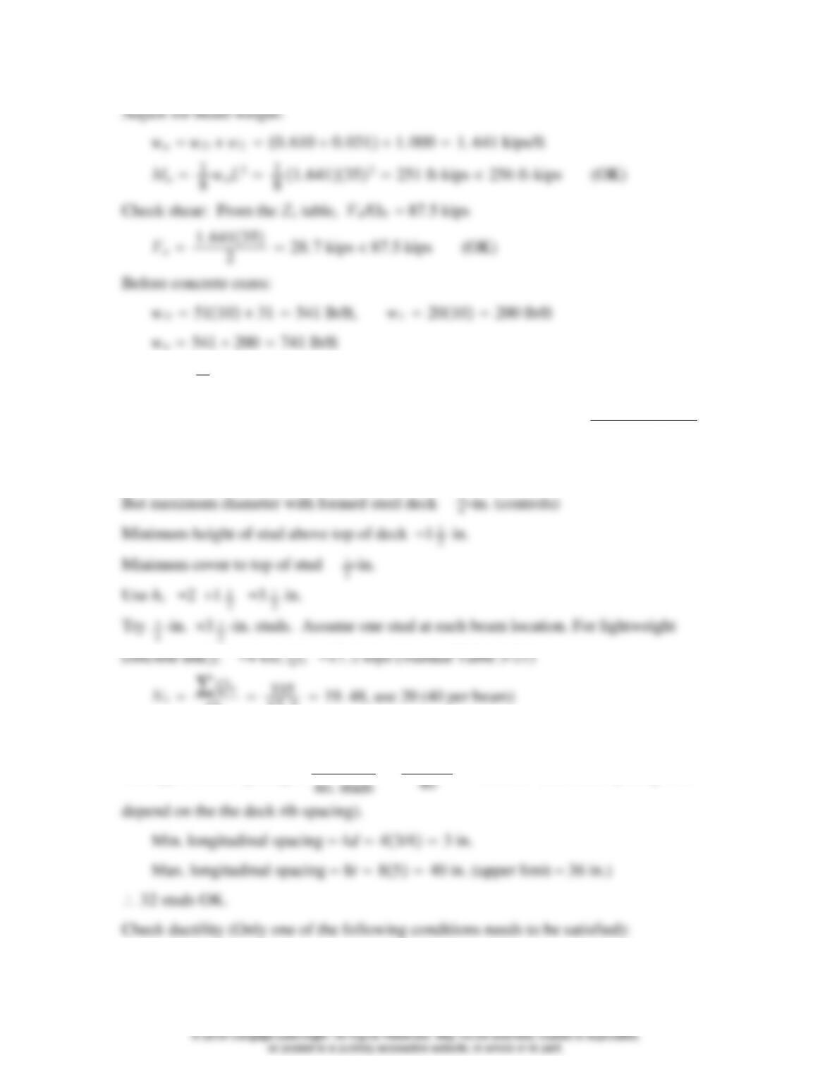
Adjust for beam weight: wu2. 332 1. 20. 0312. 369 kips/ft
From Table 3-19, bMp203 ft-kips 148 ft-kips (OK) UseaW1631
Stud anchors:
Maximum stud diameter 2. 5tf2. 50. 4401. 1 in.
But maximum diameter with formed steel deck 3
4in. (controls)
Qn
17. 2 15. 9, use 16 (32 per beam)
(Actual ∑Qn1617. 2275 kips)
The approximate spacing is L
3512
2. Qn
100 32/217. 2
3. Qn
32/217. 2
1. Compute total deflection using transformed moment of inertia:
Before concrete cures,
ΔD5wDL4
50. 541/1235 124
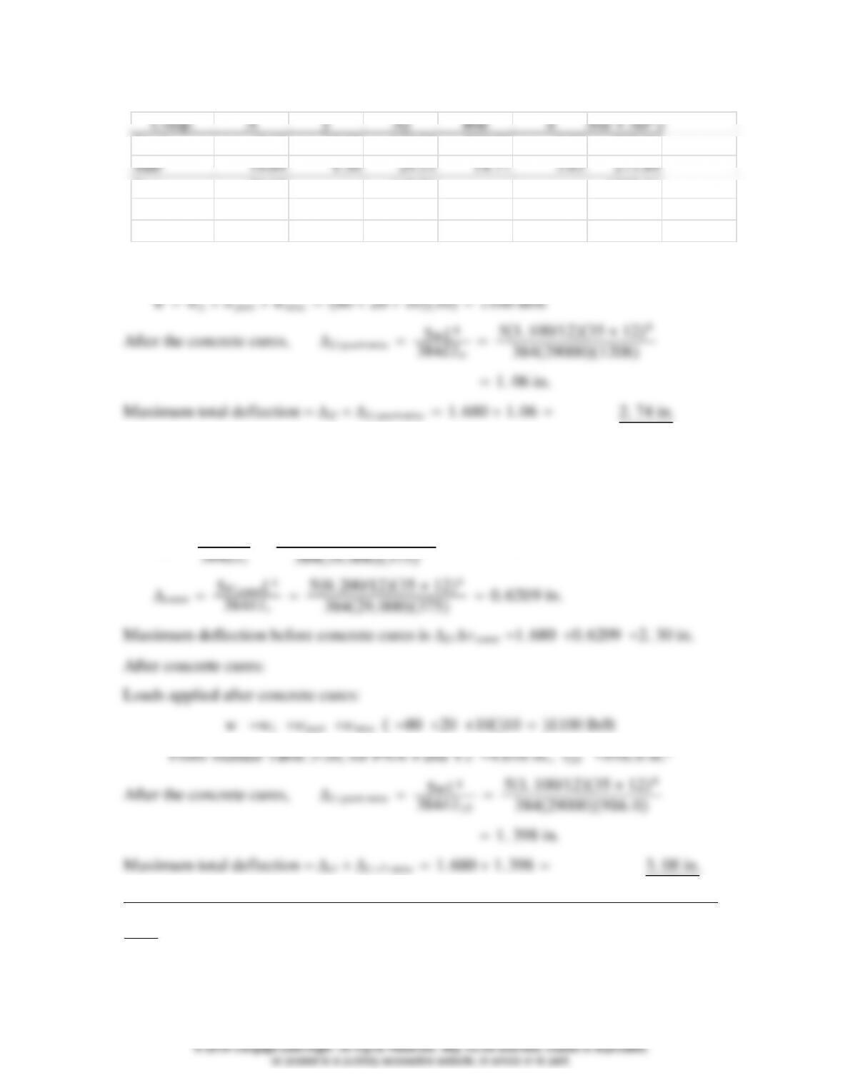
Steel 9.13 12.95 118.23 375.00 7.82 933.66
Sum 28.82 147.76 1207.51
ybar = 5.128 in. Itr = 1207.51 in.^4
Loads applied after concrete cures:
2. Compute total deflection using lower-bound moment of inertia:
Before concrete cures,
ΔD5wDL4
50. 541/1235 124
9.8–4(same as 9.8-3, but use ASD)
(a) wD51 1010610 lb/ft (neglect beam wt. and check it later.)
[9-45]
© 2018 Cengage Learning®. All Rights Reserved. May not be scanned, copied or duplicated,
or posted to a publicly accessible website, in whole or in part.
wL80 20101000 lb/ft
wawDwL0. 610 1. 000 1. 61 kips/ft
0. 85fc´b274
0. 8541050. 767 5 in.
Y2t−a
0. 85fc´b335
0. 8541050. 938 4 in.
Y2t−a
25−0. 9384
24. 531 in.
Mn/b256 ft-kips 247 ft-kips (OK)
[9-46]
© 2018 Cengage Learning®. All Rights Reserved. May not be scanned, copied or duplicated,
or posted to a publicly accessible website, in whole or in part.
Ma1
80. 741352114 ft-kips
From the Zxtable, Mnp/b135 ft-kips 114 ft-kips (OK) UseaW1631
Stud anchors:
Maximum stud diameter 2. 5tf 2. 50. 440 1. 1 in.
Qn
17. 2 19. 48, use 20 (40 per beam)
(Actual ∑Qn2017. 2344. 0 kips)
The approximate spacing is L
3512
1. Span length 35 ft 30 ft. This criterion is not met.
[9-47]
© 2018 Cengage Learning®. All Rights Reserved. May not be scanned, copied or duplicated,
or posted to a publicly accessible website, in whole or in part.
AsFy
9. 1350100
60. 28 % 50%. This criterion is met.*
3. Qn
32/217. 2
1. Compute total deflection using transformed moment of inertia:
Before concrete cures,
ΔD5wDL4
50. 541/1235 124
Slab 19.69 1.50 29.53 14.77 3.63 273.84
Sum 28.82 147.76 1207.51
ybar = 5.128 in. Itr = 1207.51 in.^4
Loads applied after concrete cures:
2. Compute total deflection using lower-bound moment of inertia:
[9-48]
© 2018 Cengage Learning®. All Rights Reserved. May not be scanned, copied or duplicated,
or posted to a publicly accessible website, in whole or in part.
Before concrete cures,
0. 5 1020 −974976. 9 in.4
After the concrete cures, ΔLpartmisc 5wL4
9.8–5
(a) Total load to be supported by the composite section (neglecting beam weight):
Slab: 4
12 15050. 0 psf
0. 85fc´b274
0. 854960. 839 5 in.
Y2t−a
24−0. 8395
23. 58 in. Use 3.5 in. (conservatively)
[9-49]
© 2018 Cengage Learning®. All Rights Reserved. May not be scanned, copied or duplicated,
or posted to a publicly accessible website, in whole or in part.
bMn342 ft-kips 329 ft-kips (OK)
1. Span length 36 ft 30 ft. This criterion is not met.
AsFy
9. 1350100
60. 28 % 50%. This criterion is met.*
3. Qn
1617. 2
9.8–6
(a) Total load to be supported by the composite section (neglecting beam weight):
Slab: 4
12 15050. 0 psf
0. 85fc´b335
0. 854961. 026 in.
Y2t−a
24−1. 026
23. 49 in. Use 3.5 in.
239 ft-kips 231 ft-kips (OK)
Adjust for beam weight: wa 1424 31 1455 lb/ft
1. Span length 36 ft 30 ft. This criterion is not met.
AsFy
9. 1350100
3. Qn
2017. 2
9.8–7
(a) Total load to be supported by the composite section (omit beam weight; check it
later):
Slab: 5
0. 85fc´b394
0. 854841. 380 in.
Y2t−a
25−1. 380
24. 31 in.
bMn1102 ft-kips 1067 ft-kips (OK)
0. 85fc´b394
0. 854841. 380 in.
Y2t−a
25−1. 380
24. 31 in.
Mn
b
732 ft-kips 679 ft-kips (OK)
Qn
15. 0 26. 3, round up to 27. total number 22754
Min. longitudinal spacing 4d45/82. 5 in.
Min. transverse spacing 4d45/82. 5 in.
1. Span length 30 ft. This criterion is met.*
AsFy
22. 450100
3. Qn
2715. 0
9.8–8
(a) Total load to be supported by the composite section (neglecting beam weight):
Deck and slab: 53 psf
0. 85fc´b408
0. 8541201. 0 in.
Y2t−a
26. 5 −1. 0
26. 0 in.
bMn893 ft-kips 873 ft-kips (OK)
0. 85fc´b662
0. 8541201. 623 in.