Shear areas: Agv 1
41. 5 32. 51
492. 25 in.2
Anv 1
0. 6FyAgv UbsFuAnt 0. 6362. 251. 0580. 281364. 92 kips
The nominal block shear strength is therefore 64.92 kips. The design block shear
strength is
Rn0. 7564. 9248. 7 kips 43.2 kips (OK)
UseaPL 1
147. 0
24. 35 6. 037 try 8 bolts (4 pair)
Determine plate thickness required for bearing: h7
81
16 15
16 in
Minimum ℓe11
53. 82t147. 0
8,Solutionis:t0. 341 4 in. Try 3/8 in.
Brg. strength of edge bolts 53. 823/820. 18 kips/bolt
0. 90Fy
0. 9364. 537 in.2
0. 75Fu
0. 75583. 379 in.2
Try a plate width of wg7in.
For gross area requirement, tAg
wg
4. 537
70. 648 in.
For net area requirement, hole diameter 7
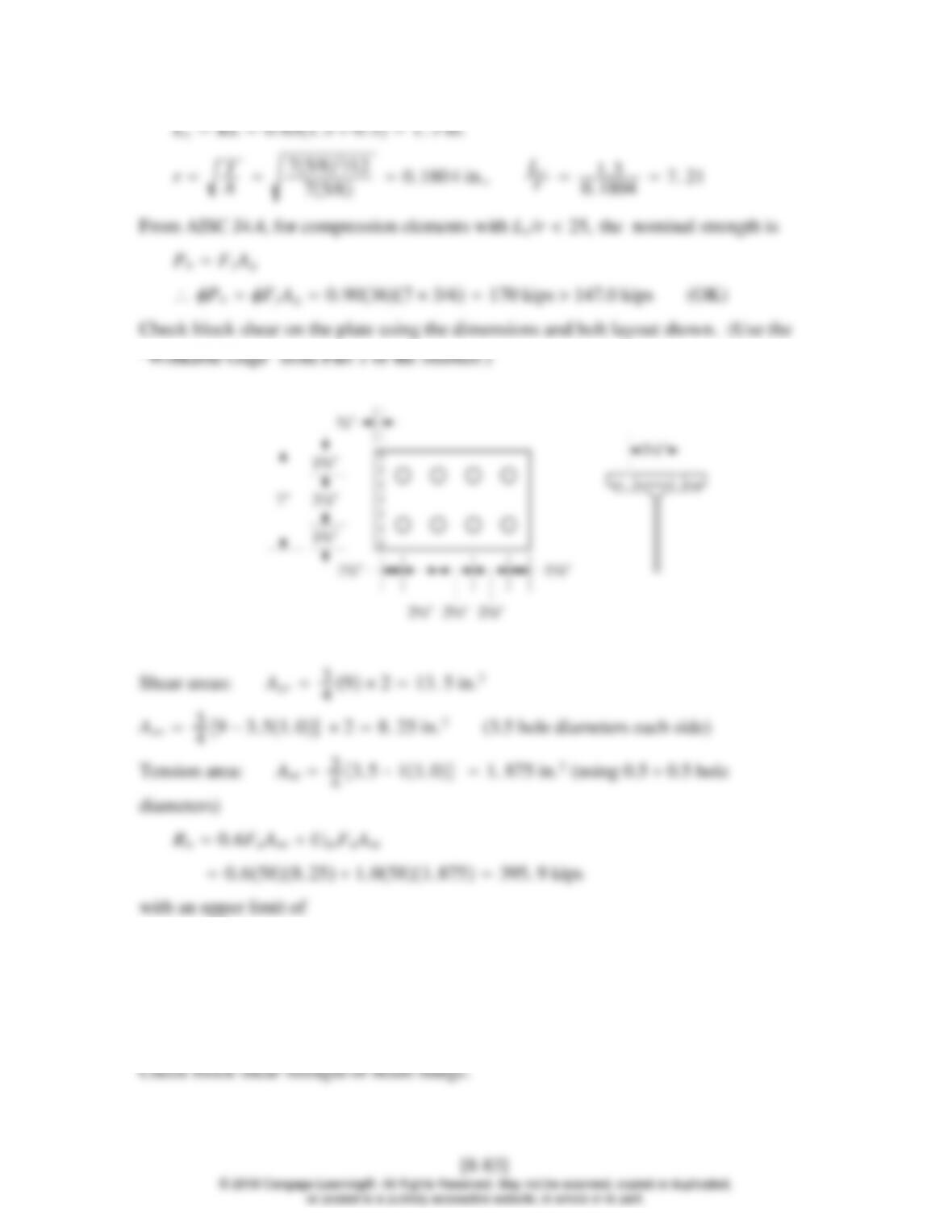
0. 6FyAgv UbsFuAnt 0. 63613. 51. 0581. 875400. 4 kips
The nominal block shear strength is therefore 395.9 kips. The design block shear
strength is
Rn0. 75395. 9297 kips 147.0 kips (OK)
0. 6FyAgv UbsFuAnt 0. 6367. 651. 0580. 6375202. 2 kips
The nominal block shear strength is therefore 199.7 kips. The design block shear
strength is
Rn0. 75199. 7149. 8 kips 147.0 kips (OK)
Afg
2. 55 57. 62496 in.-kips 208 ft-kips
bMn0. 90208187 ft-kips 216. 8 ft-kips (N.G.)
7. 95 18. 49 try 22 bolts (11 pair)
[8-84]
© 2018 Cengage Learning®. All Rights Reserved. May not be scanned, copied or duplicated,
or posted to a publicly accessible website, in whole or in part.
Bearing and block shear will be satisfactory.
Afg
2. 55 57. 62964 in.-kips 247 ft-kips
bMn0. 90247222. 3 ft-kips 216. 8 ft-kips required (OK)
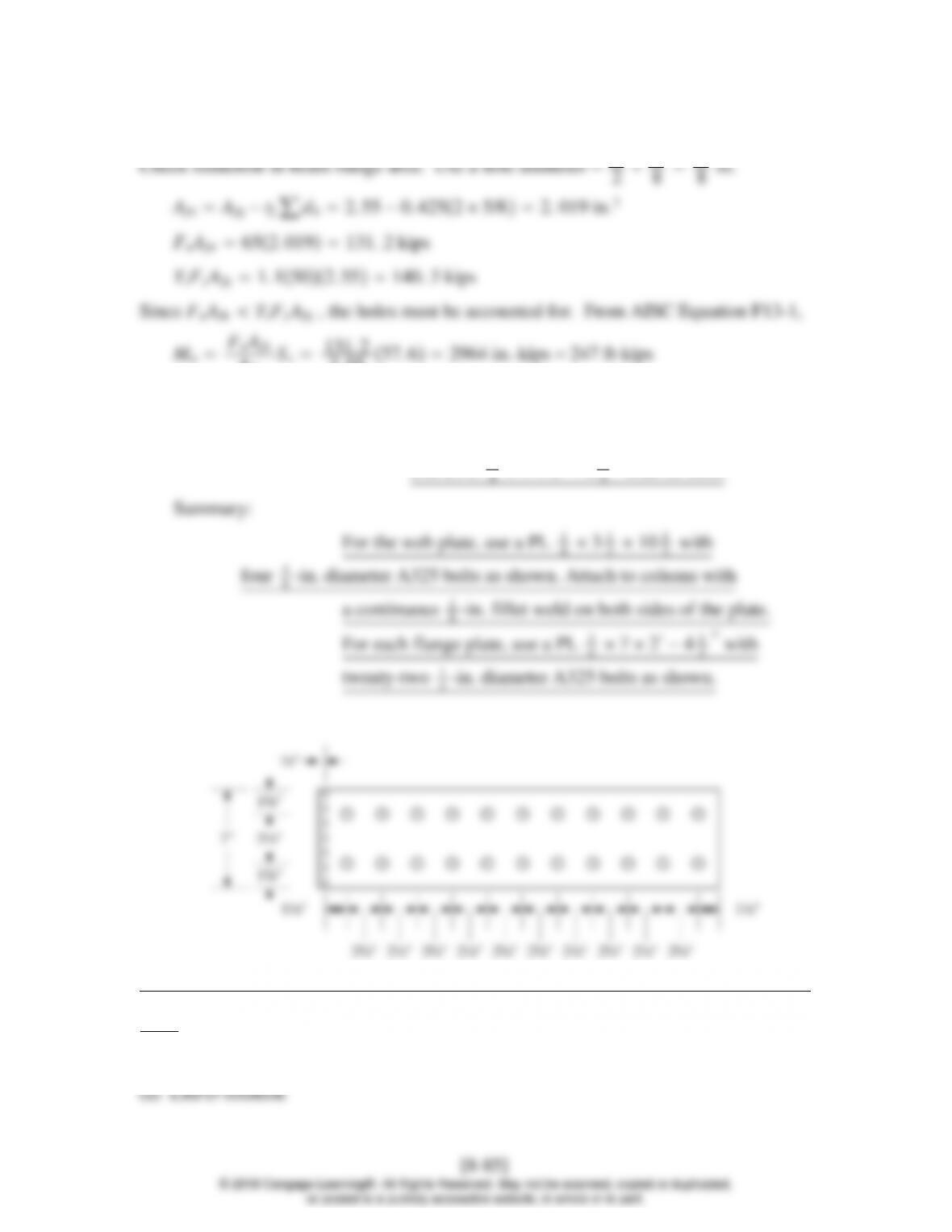
Plate length 102. 51. 5 1. 5 0. 5 28. 5 in.
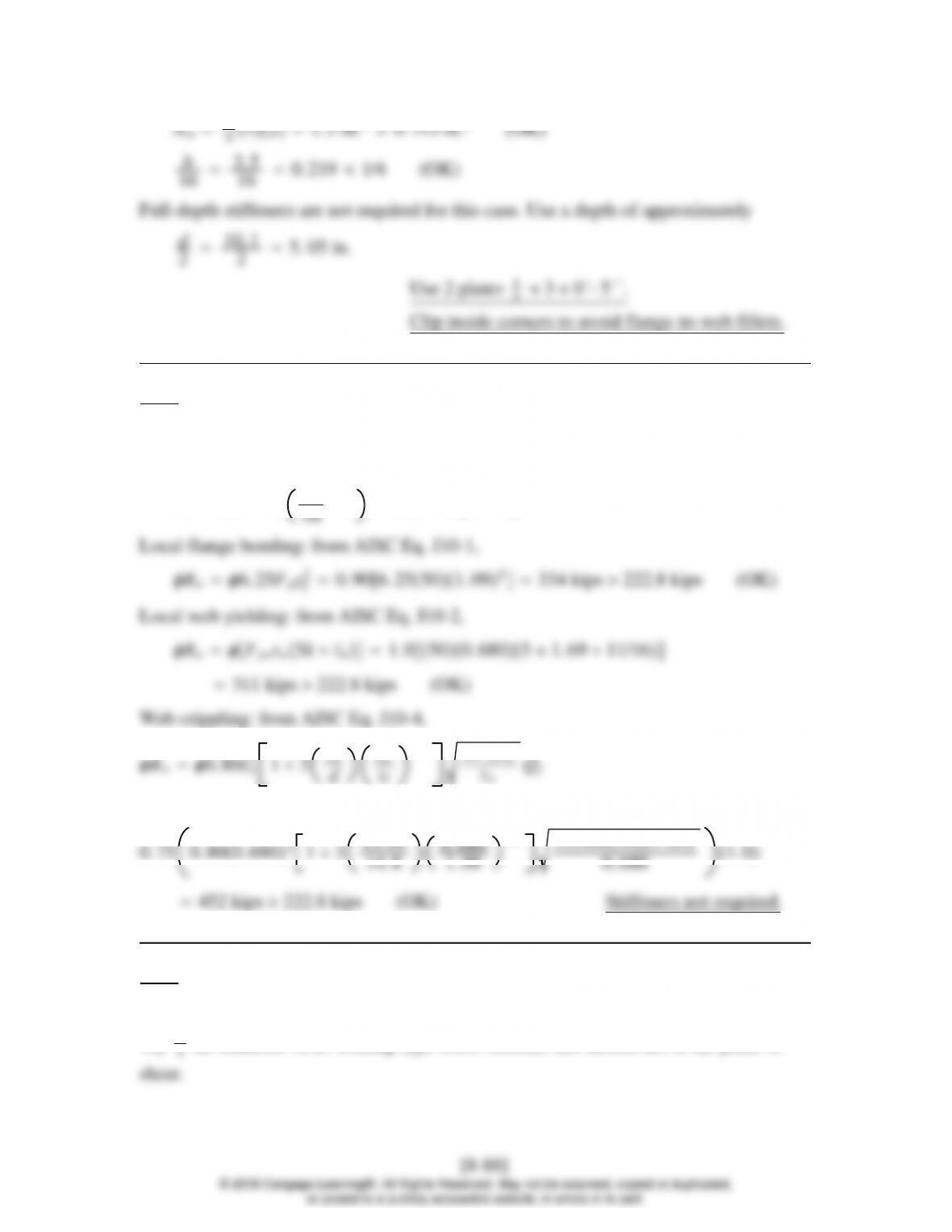
UseaPL 3
′′ with 22 bolts
8.7–1
W16 45 beam, W10 45 column, A992 steel. Flange plates are 5/8 7.
db
16. 1 130. 1 kips Pbf
Local flange bending: from AISC Eq. J10-1,
20. 906. 25500. 6202108. 1 kips 130.1 kips (N.G.)
0. 75 0. 800. 3502130. 625
10. 1
0. 620
1.5 29000500. 620
0. 350 1. 0
127. 1 kips 130.1 kips (N.G.)
Local flange bending is the worst case. Required stiffener area is
Ast Pbf −Rnmin
stFyst
130. 1 −108. 1
0. 90360. 679 in.2
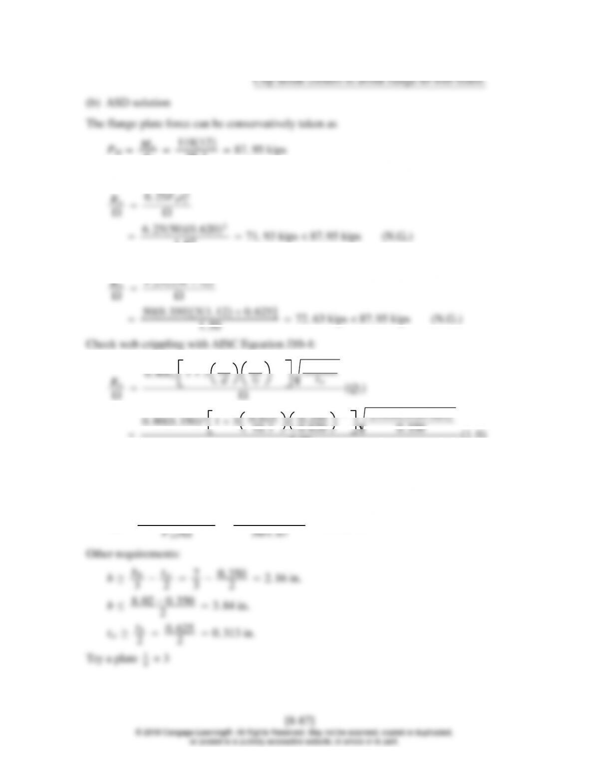
db
16. 1 87. 95 kips
Check local flange bending with AISC Equation J10-1:
2
1. 67 71. 93 kips 87. 95 kips (N.G.)
Check local web yielding with AISC Equation J10-2:
0. 800. 3502130. 625
0. 350
1.5 29000500. 620
2. 00 1. 0
84. 71 kips 87. 95 kips (N.G.)
Stiffeners are required. The smallest strength is 71.93 kips, for the limit state of local
flange bending. The required stiffener area is
Ast Pbf −Rn/min
8.7–2
LRFD solution
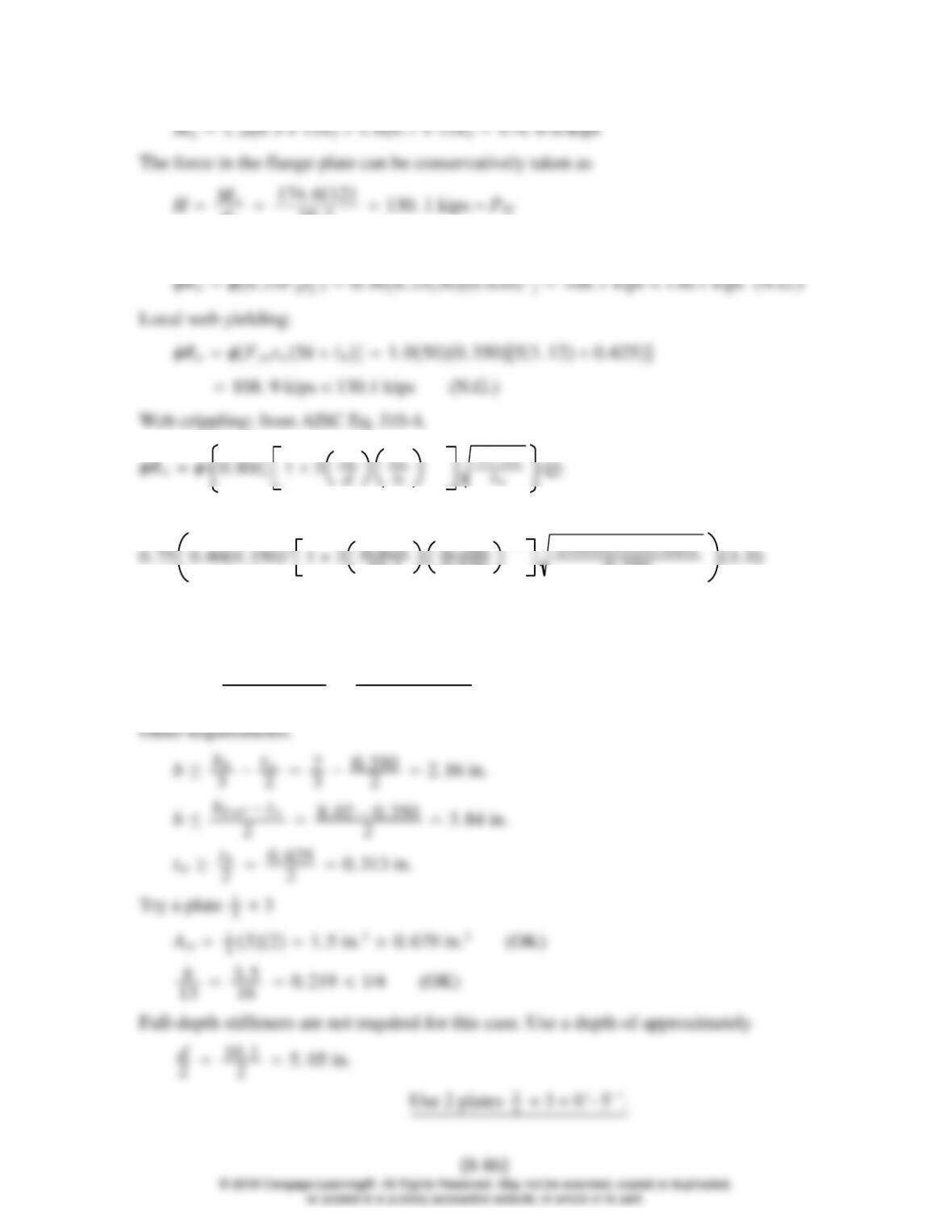
Force developed in the beam flange plate is
HFyA36 11
0. 75 0. 800. 68021311/16
0. 680
1.5 29, 000501. 09
8.7–3
(a) Web plate: neglect eccentricity.
Try 3
17. 89 2. 515 try 4 bolts
Determine plate thickness required for bearing. Assume that
Rn2. 4dtFu0. 752. 43/4t5878. 3t
Load resisted by each bolt 45
411. 25 kips. Let
ℓcℓ
e−h
21. 5 −13/16
21. 094 in.
Tearout: Rn1. 2ℓctFu0. 751. 21. 0943/165810. 71 kips
Bearing deformation: 2. 4dtFu0. 752. 43/43/165814. 68 kips
4-in. diameter A325 bolts .
Determine plate thickness required for shear. Shear yielding strength is
Rn1. 000. 60FyAgv
Let 45 1. 000. 603610. 5tt0. 198 in. Try t1
4in.
49−3. 57/8 1. 484 in.2
Tension area: Ant 1
41. 5 −0. 57/8 0. 265 6 in.2
Rn0. 6FuAnv UbsFuAnt
0. 6581. 4841. 0580. 265667. 1 kips
0. 6FyAgv UbsFuAnt 0. 6362. 251. 0580. 265664. 0 kips
The nominal block shear strength is therefore 64.0 kips. The design block shear
strength is
Rn0. 7564. 048. 0 kips 45 kips (OK)
Use a plate 1
Weld strength controls: Total length required 45/2. 784 16. 16 in.
Use a continuous 1
8-in. fillet weld on each side of plate.
Check for column stiffener requirements. The force developed in the beam flange is
HMu
22012
20. 906. 25500. 6602122. 5 kips 152.8 kips (N.G.)
13. 9
0. 660
0. 370 1. 0
137. 2 kips 152.8 kips (N.G.)
Local flange bending is the worst case. Required stiffener area is
Ast Pbf −Rnmin
stFyst
152. 8 −122. 5
0. 90360. 935 in.2
Ast 1
4321. 5 in.20.935 in.2(OK)
Check for tst b/16 :
b
16 3
16 in. 1
4in. (OK)
Full-depth stiffeners are not required for this case. Use a depth of approximately
d
Pr
Py
0. 6 (Given)
Pr1. 00. 6Py0. 6Pr0. 4Py, so use AISC Equation J10-10:
Rn0. 60Fydctw1. 4 −Pr
Py
0. 605013. 90. 3701. 4 −0. 6123. 4 kips
Rn0. 90123. 4111. 1 kips 152.8 kips (N.G.)
0. 900. 603613. 91. 4 −0. 60. 192 9 in.
where 152. 8 −111. 1 is the extra strength, in kips, to be furnished by the doubler plate.
Use a 1/4-inch doubler plate.
(The welds will not be designed. For an explanation, see Example 8.12 in the
textbook.)
dc
13. 9 51. 86 °
P41. 7
cos51. 86 °67. 52 kips
0. 9036Ast 67. 52 Ast 2. 08 in.2
Try2stiffeners,33
8, one on each side of the web.
Ast provided 233
1. 392L67. 52
1. 39290. 040. 539 sixteenths
J2.2b,
Minimum length 4w43