Archives: Solution Manual
978-0073398242 Chapter 7 Solution Manual Part 5
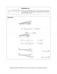
PROBLEM 7.30 For the beam and loading shown, (a) draw the shear and bending- moment diagrams, (b) determine the maximum absolute values of the shear and bending moment. SOLUTION 2 00 11 1 22 2 xx wx w x w […]
978-0073398242 Chapter 7 Solution Manual Part 4
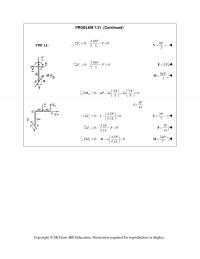
PROBLEM 7.21 (Continued) 5 14 J 7 Copyright © McGraw–Hill Education. Permission required for reproduction or display. FBD AJ: 4 10 0: 0 53 x P FVΣ= −= 8 3 P =V 3 10 0: 0 53 […]
978-0073398242 Chapter 7 Solution Manual Part 3
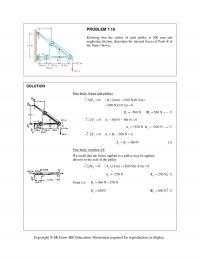
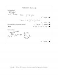
PROBLEM 7.16 Knowing that the radius of each pulley is 200 mm and neglecting friction, determine the internal forces at Point K of the frame shown. SOLUTION Free body: frame and pulleys 0: (1.8 m) (360 N)(0.2 m) (360 N)(2.6 […]
978-0073398242 Chapter 7 Solution Manual Part 2
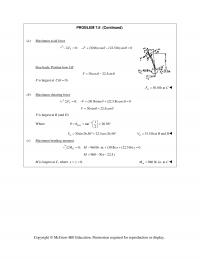
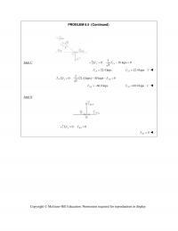
PROBLEM 7.8 (Continued) (a) Maximum axial force 0: (30 lb)cos (22.5 lb)sin 0 V FF θθ Σ = −+ − = Free body: Portion bow CK 30cos 22.5sinF θθ = − F is largest at ( 0)C θ = 30.0 […]
978-0073398242 Chapter 7 Solution Manual Part 1
CHAPTER 7 PROBLEM 7.1 Determine the internal forces (axial force, shearing force, and bending moment) at Point J of the structure indicated. Frame and loading of Problem 6.76. SOLUTION From Problem 6.76: 720 lb x =C 140 lb y =C […]
978-0073398242 Chapter 6 Solution Manual Part 27
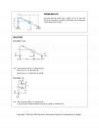
PROBLEM 6.F4 Knowing that the pulley has a radius of 0.5 m, draw the free-body diagram(s) needed to determine the components of the reactions at A and E. SOLUTION Free body: Frame Note: Sum moments about E to determine A […]
978-0073398242 Chapter 6 Solution Manual Part 26
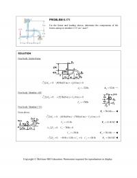
PROBLEM 6.171 For the frame and loading shown, determine the components of the forces acting on member CFE at C and F. SOLUTION Free body: Entire frame: 0: (40 lb)(13 in.) (10 in.) 0 Dx MA 52 lb, […]
978-0073398242 Chapter 6 Solution Manual Part 25
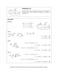
PROBLEM 6.164 Using the method of joints, determine the force in each member of the truss shown. State whether each member is in tension or compression. SOLUTION Reactions: 0: 16 kN Cx M A 0: 9 kN yy F A […]
978-0073398242 Chapter 6 Solution Manual Part 24
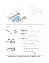
PROBLEM 6.159 The gears D and G are rigidly attached to shafts that are held by frictionless bearings. If r D 90 mm and r G 30 mm, determine (a) the couple M0 that must be applied for […]
978-0073398242 Chapter 6 Solution Manual Part 23
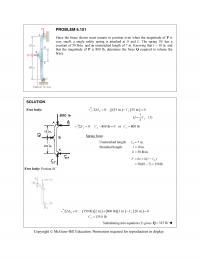
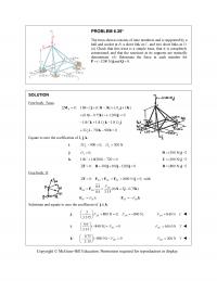
PROBLEM 6.151 Since the brace shown must remain in position even when the magnitude of P is very small, a single safety spring is attached at D and E. The spring DE has a constant of 50 lb/in. and an […]
978-0073398242 Chapter 6 Solution Manual Part 22
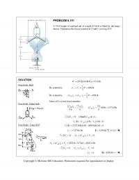
PROBLEM 6.141 A 39-ft length of railroad rail of weight 44 lb/ft is lifted by the tongs shown. Determine the forces exerted at D and F on tong BDF. SOLUTION Free body: Rail: Free body: Upper link: Free Body: Tong […]
978-0073398242 Chapter 6 Solution Manual Part 21
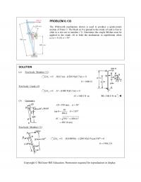
PROBLEM 6.133 The Whitworth mechanism shown is used to produce a quick-return motion of Point D. The block at B is pinned to the crank AB and is free to slide in a slot cut in member CD. Determine the […]
978-0073398242 Chapter 6 Solution Manual Part 20
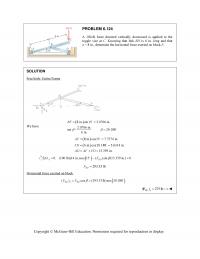
Copyright © McGraw-Hill Education. Permission required for reproduction or display. PROBLEM 6.124 A 100-lb force directed vertically downward is applied to the toggle vise at C. Knowing that link BD is 6 in. long and that a = 8 in., […]
978-0073398242 Chapter 6 Solution Manual Part 19
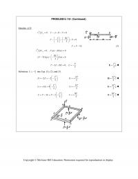
Copyright © McGraw-Hill Education. Permission required for reproduction or display. PROBLEM 6.118 (Continued) Member AFB: 0: 0 y FFABP 80 33 EE FP 3FP E (3) 0: ( ) […]
978-0073398242 Chapter 6 Solution Manual Part 18
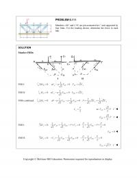
PROBLEM 6.111 Members ABC and CDE are pin-connected at C and supported by four links. For the loading shown, determine the force in each link. SOLUTION Member FBDs: I II FBD I: 1 0: 0 2 2 B y AF […]
978-0073398242 Chapter 6 Solution Manual Part 17
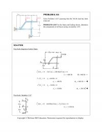
PROBLEM 6.104 Solve Problem 6.103 assuming that the 360-lb load has been removed. PROBLEM 6.103 For the frame and loading shown, determine the components of all forces acting on member ABD. SOLUTION Free body diagram of entire frame. 0: (12 […]
978-0073398242 Chapter 6 Solution Manual Part 16
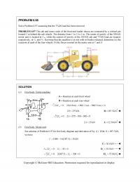
PROBLEM 6.98 Solve Problem 6.97 assuming that the 75-kN load has been removed. PROBLEM 6.97 The cab and motor units of the front-end loader shown are connected by a vertical pin located 2 m behind the cab wheels. The distance […]
978-0073398242 Chapter 6 Solution Manual Part 15
PROBLEM 6.91 Knowing that each pulley has a radius of 250 mm, determine the components of the reactions at D and E. SOLUTION Free body: Entire assembly: 0: (4.8 kN)(4.25 m) (1.5 m) 0 Ex MD 13.60 kN […]
978-0073398242 Chapter 6 Solution Manual Part 14
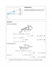
PROBLEM 6.85 (Continued) From Eq. (1): 750 N 0 150 N 750 N 0 yy y AE E 600 N 600 N yy EE Thus, reactions are 300 N x A , 150.0 N y […]
978-0073398242 Chapter 6 Solution Manual Part 13
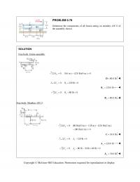
PROBLEM 6.78 Determine the components of all forces acting on member ABCD of the assembly shown. SOLUTION Free body: Entire assembly: 0: (6 in.) (120 lb)(4 in.) 0 B MD 80.0 lb D 0: 120 lb 0 […]
978-0073398242 Chapter 6 Solution Manual Part 12
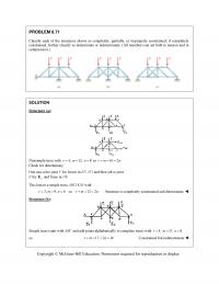
PROBLEM 6.71 Classify each of the structures shown as completely, partially, or improperly constrained; if completely constrained, further classify as determinate or indeterminate. (All members can act both in tension and in compression.) SOLUTION Structure (a): Nonsimple truss with 4,r12,m […]
978-0073398242 Chapter 6 Solution Manual Part 11
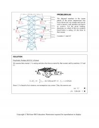
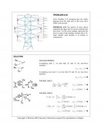
PROBLEM 6.65 The diagonal members in the center panels of the power transmission line tower shown are very slender and can act only in tension; such members are known as counters. For the given loading, determine (a) which of the […]

978-0073398242 Chapter 6 Solution Manual Part 10
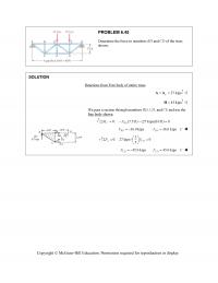
PROBLEM 6.55 A monosloped roof truss is loaded as shown. Determine the force in members CE, DE, and DF. SOLUTION Reactions at supports: Because of the symmetry of the loading, 0 11 (Total load) (8 kN) 22 x y A […]
978-0073398242 Chapter 6 Solution Manual Part 9
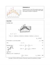
PROBLEM 6.45 Determine the force in members BD and CD of the truss shown. SOLUTION Reactions from Free body of entire truss: 27 kips y AA 45 kipsH We pass a section through members BD, CD, and CE […]
978-0073398242 Chapter 6 Solution Manual Part 8
PROBLEM 6.39* The truss shown consists of nine members and is supported by a ball and socket at B, a short link at C, and two short links at D. (a) Check that this truss is a simple truss, that […]
978-0073398242 Chapter 6 Solution Manual Part 7
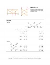
PROBLEM 6.33 For the given loading, determine the zero-force members in each of the two trusses shown. SOLUTION Truss (a): Note: Reaction at F is vertical (0). x F Joint :G 0,F 0 DG F Joint :D 0,F 0 […]
978-0073398242 Chapter 6 Solution Manual Part 6
PROBLEM 6.26 Solve Problem 6.24 assuming that the cables hanging from the right side of the tower have fallen to the ground. PROBLEM 6.24 The portion of truss shown represents the upper part of a power transmission line tower. For […]
978-0073398242 Chapter 6 Solution Manual Part 5
PROBLEM 6.21 Determine the force in each of the members located to the left of FG for the scissors roof truss shown. State whether each member is in tension or compression. SOLUTION Free Body: Truss: 0: 0 xx F A […]
978-0073398242 Chapter 6 Solution Manual Part 4
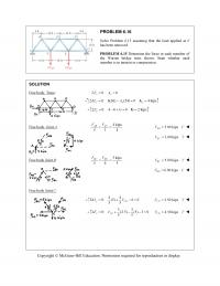
PROBLEM 6.16 Solve Problem 6.15 assuming that the load applied at E has been removed. PROBLEM 6.15 Determine the force in each member of the Warren bridge truss shown. State whether each member is in tension or compression. SOLUTION Free […]
978-0073398242 Chapter 6 Solution Manual Part 3
PROBLEM 6.10 (Continued) Free body: Joint B: 11 0: 7.07 0 22 yBD FF 7.07 kN BD FT 11 0: 5 (7.07) 7.07 0 22 xBA FF 5.00 kN BA FC […]
978-0073398242 Chapter 6 Solution Manual Part 2
PROBLEM 6.5 (Continued) Joint C: 1 0: 10 kips 0 5 yCA FF 22.4 kips CA F 22.4 kips CA FT 2 0: (22.4 kips) 40 kips 0 5 xCB FF 60.0 kips CB […]
978-0073398242 Chapter 6 Solution Manual Part 1
CHAPTER 6 PROBLEM 6.1 Using the method of joints, determine the force in each member of the truss shown. State whether each member is in tension or compression. SOLUTION Free body: Entire truss: 0: 0 0 yy y FB […]
978-0073398242 Chapter 5 Solution Manual Part 19
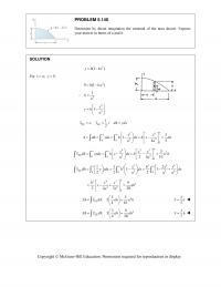
PROBLEM 5.140 Determine by direct integration the centroid of the area shown. Express your answer in terms of a and h. SOLUTION 3 (1 )yh kx For ,0.xay 3 0(1 )hka 3 1 ka 3 3 1x yh a […]
978-0073398242 Chapter 5 Solution Manual Part 18
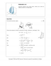
PROBLEM 5.134* Locate the centroid of the section shown, which was cut from an elliptical cylinder by an oblique plane. SOLUTION First note that symmetry implies 0x Choose as the element of volume a vertical slice of width zx, […]
978-0073398242 Chapter 5 Solution Manual Part 17
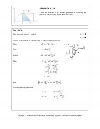
PROBLEM 5.128* Locate the centroid of the volume generated by revolving the portion of the sine curve shown about the x-axis. SOLUTION First, note that symmetry implies 0y 0z Choose as the element of volume a disk of […]
978-0073398242 Chapter 5 Solution Manual Part 16
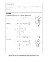
PROBLEM 5.122 Determine by direct integration the values of x for the two volumes obtained by passing a vertical cutting plane through the given shape of Figure 5.21. The cutting plane is parallel to the base of the given shape […]
978-0073398242 Chapter 5 Solution Manual Part 15
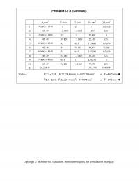
PROBLEM 5.113 (Continued) 2 ,mmA ,mm x ,mm y 3 ,mmxA 3 ,mmyA 1 (74)(60) 4440 0 43 0 190,920 2 565.49 2.1803 2.1803 1233 1233 3 (30)(60) 1800 21 0 37,800 0 4 565.49 39.820 2.1803 22,518 1233 5 […]
978-0073398242 Chapter 5 Solution Manual Part 14
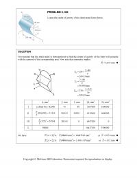
PROBLEM 5.106 Locate the center of gravity of the sheet-metal form shown. SOLUTION First assume that the sheet metal is homogeneous so that the center of gravity of the form will coincide with the centroid of the corresponding area. Now […]
978-0073398242 Chapter 5 Solution Manual Part 13
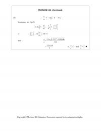
PROBLEM 5.98 (Continued) (b) ?when 0.4 hYa a Substituting into Eq. (1) 2 3 (0.4)4 4 8 hh aa aa or 2 33.20.80 hh aa […]
978-0073398242 Chapter 5 Solution Manual Part 12
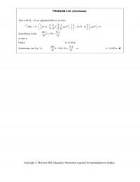
PROBLEM 5.92 (Continued) Then with 0 y B (as explained above), we have 22 2184 1 0: (0.4) (0.25 ) 0 3 3 15 15 3 2 Ad Mdgdhgd […]
978-0073398242 Chapter 5 Solution Manual Part 11
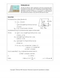
PROBLEM 5.83 The base of a dam for a lake is designed to resist up to 120 percent of the horizontal force of the water. After construction, it is found that silt (that is equivalent to a liquid of density […]
978-0073398242 Chapter 5 Solution Manual Part 10
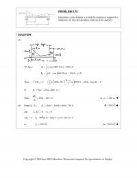
PROBLEM 5.75 Determine (a) the distance a so that the reaction at support B is minimum, (b) the corresponding reactions at the supports. SOLUTION (a) We have I II 1( m)(1800 N/m) 900 N 2 1[(4 )m](600 N/m) 300(4 ) […]
978-0073398242 Chapter 5 Solution Manual Part 9
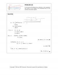
PROBLEM 5.66 For the beam and loading shown, determine (a) the magnitude and location of the resultant of the distributed load, (b) the reactions at the beam supports. SOLUTION I II 1 ( ) (400 N/m) (6 m) 2 1200 […]
978-0073398242 Chapter 5 Solution Manual Part 8
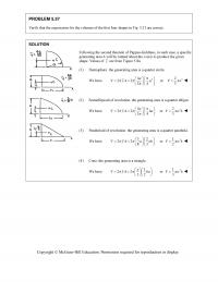
PROBLEM 5.57 Verify that the expressions for the volumes of the first four shapes in Fig. 5.21 are correct. SOLUTION Following the second theorem of Pappus-Guldinus, in each case, a specific generating area A will be rotated about the x-axis […]
978-0073398242 Chapter 5 Solution Manual Part 7
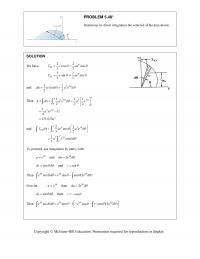
PROBLEM 5.48* Determine by direct integration the centroid of the area shown. SOLUTION We have 22 cos cos 33 22 sin sin 33 EL EL xr ae yr ae and 22 11 ()( ) […]
978-0073398242 Chapter 5 Solution Manual Part 6
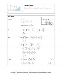
PROBLEM 5.42 Determine by direct integration the centroid of the area shown . SOLUTION We have 2 2 2 2 11 22 1 EL EL xx axx yy LL xx dA ydx a dx LL […]
978-0073398242 Chapter 5 Solution Manual Part 5
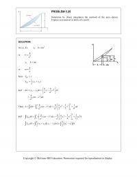
PROBLEM 5.35 Determine by direct integration the centroid of the area shown. Express your answer in terms of a and h. SOLUTION At (, ),ah 1 :yhka or 2 h ka 2 :yhma or h ma Now 12 […]
978-0073398242 Chapter 5 Solution Manual Part 4
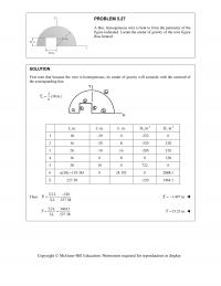
PROBLEM 5.27 A thin, homogeneous wire is bent to form the perimeter of the figure indicated. Locate the center of gravity of the wire figure thus formed. SOLUTION First note that because the wire is homogeneous, its center of gravity […]
978-0073398242 Chapter 5 Solution Manual Part 3
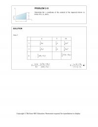
PROBLEM 5.18 Determine the x coordinate of the centroid of the trapezoid shown in terms of h1, h2, and a. SOLUTION Area 1: A x x A 1 1 1 2ha 1 3a 2 1 1 6ha 2 2 1 […]
978-0073398242 Chapter 5 Solution Manual Part 2
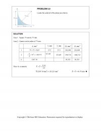
PROBLEM 5.9 Locate the centroid of the plane area shown. SOLUTION Area 1: Square 75 mm by 75 mm. Area 2: Quarter circle radius of 75 mm. 2 ,mmA ,mm x ,mm y 3 ,mmxA 3 ,mmyA 1 75 75 […]