Archives: Solution Manual
978-0073398242 Chapter 9 Solution Manual Part 14
PROBLEM 9.96 Using Mohr’s circle, determine the moments of inertia and the product of inertia of the L152 102 12.7-mm angle cross section of Problem 9.78 with respect to new centroidal axes obtained by rotating the x and y axes […]
978-0073398242 Chapter 9 Solution Manual Part 13
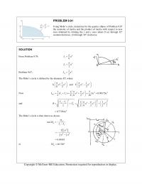
PROBLEM 9.91 Using Mohr’s circle, determine for the quarter ellipse of Problem 9.67 the moments of inertia and the product of inertia with respect to new axes obtained by rotating the x and y axes about O (a) through 45 […]
978-0073398242 Chapter 9 Solution Manual Part 12
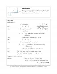
PROBLEM 9.82 Determine the moments of inertia and the product of inertia of the area of Problem 9.75 with respect to new centroidal axes obtained by rotating the x and y axes 45 clockwise. SOLUTION From Problem 9.75: 4 471,040 […]
978-0073398242 Chapter 9 Solution Manual Part 11
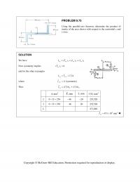
PROBLEM 9.75 Using the parallel-axis theorem, determine the product of inertia of the area shown with respect to the centroidal x and y axes. SOLUTION We have 123 ()() () xy xy xy xy II I I Now symmetry implies […]
978-0073398242 Chapter 9 Solution Manual Part 10
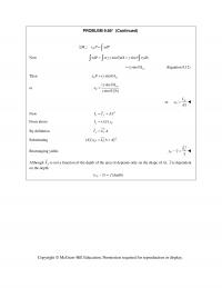
PROBLEM 9.66* (Continued) : yP M xP xdP Now (sin) sin x dP x y dA xydA (sin) x y I (Equation 9.12) Then (sin) Pxy x PI or (sin) […]
978-0073398242 Chapter 9 Solution Manual Part 9
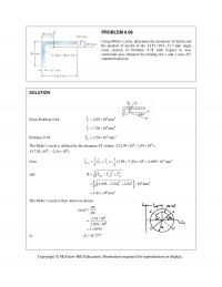
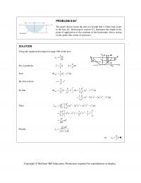
PROBLEM 9.60* The panel shown forms the end of a trough that is filled with water to the line AA. Referring to section 9.2, determine the depth of the point of application of the resultant of the hydrostatic forces acting […]
978-0073398242 Chapter 9 Solution Manual Part 8
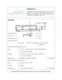
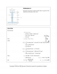
PROBLEM 9.53 A channel and a plate are welded together as shown to form a section that is symmetrical with respect to the y axis. Determine the moments of inertia of the combined section with respect to its centroidal x […]
978-0073398242 Chapter 9 Solution Manual Part 7
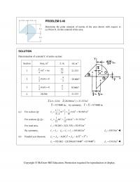
PROBLEM 9.46 Determine the polar moment of inertia of the area shown with respect to (a) Point O, (b) the centroid of the area. SOLUTION Determination of centroid C of entire section: Section Area, in2 ,in.x 3 ,inxA 1 2 […]
978-0073398242 Chapter 9 Solution Manual Part 6
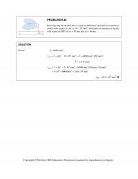
PROBLEM 9.40 Knowing that the shaded area is equal to 6000 mm2 and that its moment of inertia with respect to AA is 18 106 mm4, determine its moment of inertia with respect to BB for d1 = 50 […]
978-0073398242 Chapter 9 Solution Manual Part 5
PROBLEM 9.31 Determine the moment of inertia and the radius of gyration of the shaded area with respect to the x axis. SOLUTION First note that 123 2 2 2 [(24)(6) (8)(48) (48)(6)] mm (144 384 288) mm 816 mm […]
978-0073398242 Chapter 9 Solution Manual Part 4
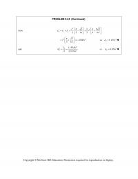
PROBLEM 9.24 (Continued) Now 44 2 3 16 3 4 64 Pxy JII r 44 31.15545 316 rr 4 or 1.155 P J r […]
978-0073398242 Chapter 9 Solution Manual Part 3
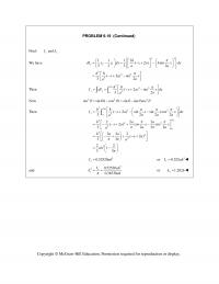
PROBLEM 9.19 (Continued) Find: and xx Ik We have 33 21 333 3 11 12 (2) sin 33 3 2 8(2)sin 32 xh dI y y dx x a h x dx aa hxa x a a […]
978-0073398242 Chapter 9 Solution Manual Part 2
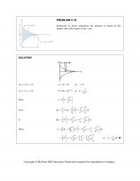
PROBLEM 9.10 Determine by direct integration the moment of inertia of the shaded area with respect to the x axis. SOLUTION At 0, :xyb (1 0)bc or cb At ,0:xay 1/2 0(1 )bka 1/2 1 or ka Then 1/2 […]
978-0073398242 Chapter 9 Solution Manual Part 1
CHAPTER 9 PROBLEM 9.1 Determine by direct integration the moment of inertia of the shaded area with respect to the y axis. SOLUTION At 2 0, : 0xybbka 2 b ka then 2 2 ; b […]
978-0073398242 Chapter 8 Solution Manual Part 19
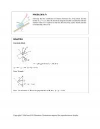
PROBLEM 8.F1 Knowing that the coefficient of friction between the 25-kg block and the incline is s = 0.25, draw the free-body diagram needed to determine both the smallest value of P required to start the block moving up […]
978-0073398242 Chapter 8 Solution Manual Part 18
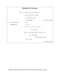
PROBLEM 8.136 (Continued) 0: (32 in.) (12 in.) (24 in.) 0 AB MPWN 8 3 6 0 0.25 0.3 P PW P W tip ( 0.25 OK)PWP 0.25(120 lb)P or 30.0 lb P (c) […]
978-0073398242 Chapter 8 Solution Manual Part 17
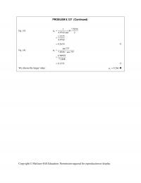
PROBLEM 8.127 (Continued) Eq. (3): 17.5056 ln 4.9742 rad 2 1.3225 4.9742 s 0.2659 Eq. (4): sin 75 7.5056 cos 75 0.96953 7.2468 s 0.1333 We choose the larger […]
978-0073398242 Chapter 8 Solution Manual Part 16
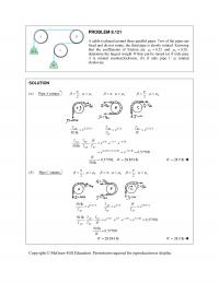
PROBLEM 8.121 A cable is placed around three parallel pipes. Two of the pipes are fixed and do not rotate; the third pipe is slowly rotated. Knowing that the coefficients of friction are 0.25 s and 0.20, k […]
978-0073398242 Chapter 8 Solution Manual Part 15
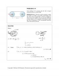
PROBLEM 8.114 Solve Problem 8.113 assuming that the belt is looped around the pulleys in a figure eight. PROBLEM 8.113 A flat belt is used to transmit a couple from pulley A to pulley B. The radius of each pulley […]
978-0073398242 Chapter 8 Solution Manual Part 14
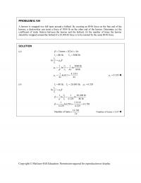
Copyright © McGraw-Hill Education. Permission required for reproduction or display. PROBLEM 8.104 A hawser is wrapped two full turns around a bollard. By exerting an 80-lb force on the free end of the hawser, a dockworker can resist a force […]
978-0073398242 Chapter 8 Solution Manual Part 13
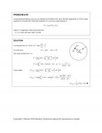
Copyright © McGraw-Hill Education. Permission required for reproduction or display. PROBLEM 8.95* Assuming that bearings wear out as indicated in Problem 8.94, show that the magnitude M of the couple required to overcome the frictional resistance of a worn-out collar […]
978-0073398242 Chapter 8 Solution Manual Part 12
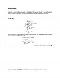
Copyright © McGraw-Hill Education. Permission required for reproduction or display. PROBLEM 8.85 A scooter is to be designed to roll down a 2 percent slope at a constant speed. Assuming that the coefficient of kinetic friction between the 25-mm-diameter axles […]
978-0073398242 Chapter 8 Solution Manual Part 11
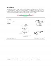
PROBLEM 8.75 The ends of two fixed rods A and B are each made in the form of a single-threaded screw of mean radius 6 mm and pitch 2 mm. Rod A has a right-handed thread and rod B has […]
978-0073398242 Chapter 8 Solution Manual Part 10
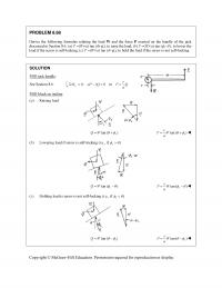
PROBLEM 8.68 Derive the following formulas relating the load W and the force P exerted on the handle of the jack discussed in Section 8.6. (a) P (Wr/a) tan ( s ), to raise the load; (b) […]
978-0073398242 Chapter 8 Solution Manual Part 9
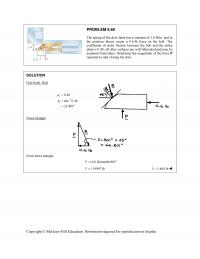
PROBLEM 8.60 The spring of the door latch has a constant of 1.8 lb/in. and in the position shown exerts a 0.6-lb force on the bolt. The coefficient of static friction between the bolt and the strike plate is 0.40; […]
978-0073398242 Chapter 8 Solution Manual Part 8
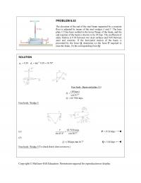
PROBLEM 8.52 The elevation of the end of the steel beam supported by a concrete floor is adjusted by means of the steel wedges E and F. The base plate CD has been welded to the lower flange of the […]
978-0073398242 Chapter 8 Solution Manual Part 7
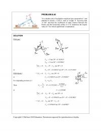
PROBLEM 8.46 Two slender rods of negligible weight are pin-connected at C and attached to blocks A and B, each of weight W. Knowing that 80 and that the coefficient of static friction between the blocks and […]
978-0073398242 Chapter 8 Solution Manual Part 6
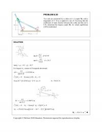
PROBLEM 8.39 Two rods are connected by a collar at B. A couple M A with a magnitude of 15 N·m is applied to rod AB. Knowing that the coefficient of static friction between the collar and the rod is […]
978-0073398242 Chapter 8 Solution Manual Part 5
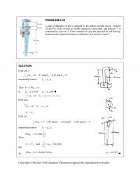
PROBLEM 8.33 A pipe of diameter 60 mm is gripped by the stillson wrench shown. Portions AB and DE of the wrench are rigidly attached to each other, and portion CF is connected by a pin at D. If the […]
978-0073398242 Chapter 8 Solution Manual Part 4
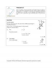
PROBLEM 8.24 End A of a slender, uniform rod of length L and weight W bears on a surface as shown, while end B is supported by a cord BC. Knowing that the coefficients of friction are 0.40 s […]
978-0073398242 Chapter 8 Solution Manual Part 3
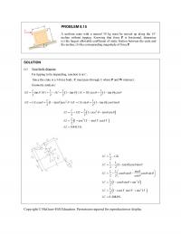
PROBLEM 8.15 A uniform crate with a massof 30 kg must be moved up along the 15° incline without tipping. Knowing that force P is horizontal, determine (a) the largest allowable coefficient of static friction between the crate and the […]
978-0073398242 Chapter 8 Solution Manual Part 2
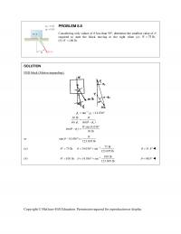
PROBLEM 8.8 Considering only values of less than 90, determine the smallest value of required to start the block moving to the right when (a) 75 lb,W (b) 100 lb.W SOLUTION FBD block (Motion impending): 1 tan […]
978-0073398242 Chapter 8 Solution Manual Part 1
CHAPTER 8 PROBLEM 8.1 Determine whether the block shown is in equilibrium and find the magnitude and direction of the friction force whenP 150 N. SOLUTION Assume equilibrium: 0: (500 N)sin 20 (150 N) cos 20 0 x FF […]
978-0073398242 Chapter 7 Solution Manual Part 22
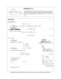
PROBLEM 7.161 For the beam shown, draw the shear and bending–moment diagrams, and determine the magnitude and location of the maximum absolute value of the bending moment, knowing that (a) M = 0, (b) M = 24 kip ∙ ft. […]
978-0073398242 Chapter 7 Solution Manual Part 21
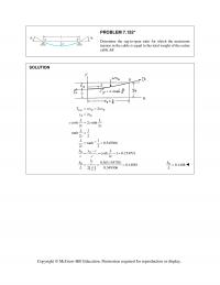
PROBLEM 7.152* Determine the sag–to–span ratio for which the maximum tension in the cable is equal to the total weight of the entire cable AB. SOLUTION ( ) max 1 2 2 2 cosh 2 sinh 22 1 tanh 22 […]
978-0073398242 Chapter 7 Solution Manual Part 20
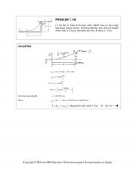
PROBLEM 7.145 To the left of Point B the long cable ABDE rests on the rough horizontal surface shown. Knowing that the mass per unit length of the cable is 2 kg/m, determine the force F when a= 3.6 m. […]
978-0073398242 Chapter 7 Solution Manual Part 19
PROBLEM 7.135 A counterweight D is attached to a cable that passes over a small pulley at A and is attached to a support at B. Knowing that L= 45 ft and h= 15 ft, determine (a) the length of […]
978-0073398242 Chapter 7 Solution Manual Part 18
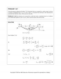
PROBLEM 7.125* Using the property indicated in Problem 7.124, determine the curve assumed by a cable of span L and sag h carrying a distributed load w=w0 cos ( π x/L), where x is measured from mid–span. Also determine the […]
978-0073398242 Chapter 7 Solution Manual Part 17
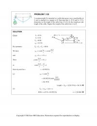
PROBLEM 7.116 Cable ACB supports a load uniformly distributed along the horizontal as shown. The lowest Point C is located 9 m to the right of A. Determine (a) the vertical distance a, (b) the length of the cable, (c) […]
978-0073398242 Chapter 7 Solution Manual Part 16
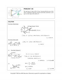
PROBLEM 7.108 The total mass of cable ACB is 20 kg. Assuming that the mass of the cable is distributed uniformly along the horizontal, determine (a) the sag h, (b) the slope of the cable at A. SOLUTION Free body: […]
978-0073398242 Chapter 7 Solution Manual Part 15
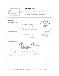
PROBLEM 7.100 Determine (a) the distance dC for which portion BC of the cable is horizontal, (b) the corresponding components of the reaction at E. SOLUTION Free body: Portion CDE 0: 2(2 kips) 0 4 kips yy y FE EΣ= […]
978-0073398242 Chapter 7 Solution Manual Part 14
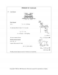
PROBLEM 7.92* (Continued) (b) Load diagram Shear diagram At A: 2.26 kips A VA = = + To determine Point G where 0,V= we write GC VV w µ −=− 0 (1.22 kips) (0.25 kip/ft) µ −=− 4.88 ft µ […]
978-0073398242 Chapter 7 Solution Manual Part 13
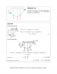
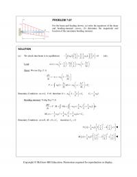
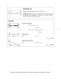
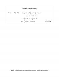
PROBLEM 7.87 For the beam and loading shown, (a) write the equations of the shear and bending–moment curves, (b) determine the magnitude and location of the maximum bending moment. SOLUTION (a) We check that beam is in equilibrium ( ) […]
978-0073398242 Chapter 7 Solution Manual Part 12
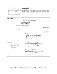
PROBLEM 7.78 For the beam and loading shown, (a) draw the shear and bending– moment diagrams, (b) determine the magnitude and location of the maximum absolute value of the bending moment. SOLUTION 0: (8.75)(1.75) (2.5) 0 A MBΣ= − = […]
978-0073398242 Chapter 7 Solution Manual Part 11
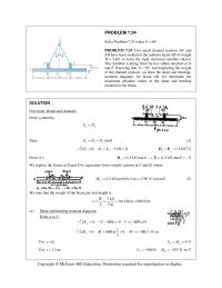
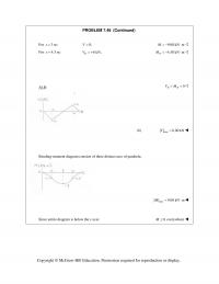
PROBLEM 7.68 Using the method of Section 7.6, solve Problem 7.34. PROBLEM 7.34 For the beam and loading shown, (a) draw the shear and bending–moment diagrams, (b) determine the maximum absolute values of the shear and bending moment. SOLUTION Free […]
978-0073398242 Chapter 7 Solution Manual Part 10
PROBLEM 7.59 (Continued) We set 2 2 22 1 11 111 | | | |: 2 82 282 AC M M wa wL wLa wa wL wLa= −=− +=− 22 0.25 0a La L+− = 22 22 max 11 ( […]
978-0073398242 Chapter 7 Solution Manual Part 9
PROBLEM 7.54 Solve Problem 7.53 when 60 . θ = ° PROBLEM 7.53 Two small channel sections DF and EH have been welded to the uniform beam AB of weight W 3 kN= to form the rigid structural member shown. […]
978-0073398242 Chapter 7 Solution Manual Part 8
PROBLEM 7.48 (Continued) Copyright © McGraw–Hill Education. Permission required for reproduction or display. For 3m:x= 0,V= 9.00 kN mM=−⋅ For 4.5 m:x= 6 kN, D V= + 4.50 kN m D M=−⋅ At B: 0 BB VM= = […]
978-0073398242 Chapter 7 Solution Manual Part 7
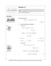
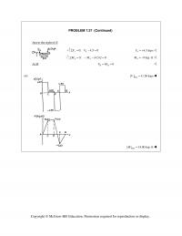
PROBLEM 7.43 Assuming the upward reaction of the ground on beam AB to be uniformly distributed and knowing that P =wa, (a) draw the shear and bending-moment diagrams, (b) determine the maximum absolute values of the shear and bending moment. […]
978-0073398242 Chapter 7 Solution Manual Part 6
PROBLEM 7.37 (Continued) max Copyright © McGraw–Hill Education. Permission required for reproduction or display. Just to the right of E: 4 0: 4.5 0 y FVΣ= − = 44.5 kipsV= + 44 0: (4.5)2 0MM Σ= − − = […]