Archives
Chapter 1 Basic Concepts in Strength of Materials
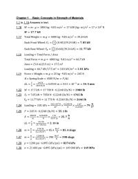
Chapter 1 Basic Concepts in Strength of Materials 1.1 to 1.15 Answers in text. 1.22 1.23 1.24 1.25 1.26 1.27 1.29 1.30 1.16 1.17 1.31 1.35 1.36 1.37 1.38 1.39 1.40 1.41 1.42 1.32 1.33 1.34 1.43 1.44 1.45 1.46 […]
Chapter 10 Listed below are the significant numerical
10-54 Let w = 32 lb/in 448 lb – Resultant 650 lb R B = 658 lb RA = 456 lb 456 V (lb) M (lb in) 3250 -650 10-55 : Combined Stresses Note: The complete solutions for problems 10-56 […]
Chapter 10 Force system transformed into components
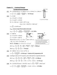
230 lb M Chapter 10 Combined Stresses Combined Normal Stresses 10-1 10-2 10-3 At At into components and moment, M1, due to the 12-in offset below 10-4 10-5 At At 10-6 F h F Fv F h Fv Note: Force […]
Chapter 11 Eccentrically Loaded Column Analysis Summary
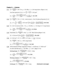
Chapter 11 Columns 11-1 11-4 F 11-5 11-6 ; [ 11-2 11-3 [ 11-7 ; 11-8 11-9 ; 11-10 ; ; 11-11 11-12 11-13 Johnson Eqn 11-14 [ 11-15 : ; : 2.4 m F W Fv Fh – Tan-1(1/2.4) […]
Chapter 12 calls for drawings to be made for one or more of
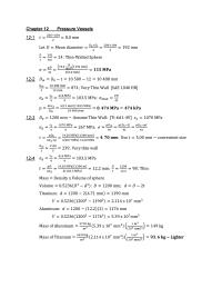
Chapter 12 Pressure Vessels 12-1 ; 12-3 ] ; 12-4 ; 12-2 ; 12-5 12-6 ; 12-7 ; 12-8 ; 12-9 ; 12-10 ; 12-11 ; 12-12 ; ; 12-13 12-14 ; 12-15 12-16 17 12.45 19 10.75 21 9.52 […]
Chapter 13 Note that the problems fall into groups of similar
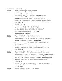
Chapter 13 Connections 13.1(a) 13.1(b) , 13.1(c) )] , ; 13.1(d) [ 13.2(a) [ , ; . 13.2(b) , 13.2(c) [ , 13.2(d) [ 13.3(a) ] 13.3(b) 13.3(c) 13.3(d) : 13.4(a) 13.4(b) ] 13.4(c) ] 13.4(d) ] 13.5 13.6 [ […]
Chapter 2 Design Properties of Materials
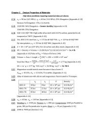
Chapter 2 Design Properties of Materials 2-14 2-17 2-18 2-19 2-20 2-21 2-23 2-24 2-29 2-31 2-32 2-15 2-16 2-44 2-45 2-51 2-52 2-60 2-61 2-62 See Table 2 – 15 for data. Use Equation (2 – 10): See Table […]
Chapter 3 Results are summarized on page following
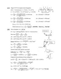
3-79 ; 3-80 W = 6671 N W = 6671 N AC BC Vector Triangle ; ; 7.00 in C D 10 mm 20 mm 15 mm Square cross sections 30 40 50 40 kN 40 kN AC 14.00 in […]
Chapter 3 Thermal Deformation And Thermal Stress
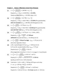
Chapter 3 Design of Members Under Direct Stresses 3-1 3-4 3-5 3-6 3-7 3-8 3-2 3-3 3-9 3-10 3-11 3-12 3-13 3-14 3-15 3-16 3-17 3-18 3-19 3-20 Elastic Deformation in Tension and Compression Members 3-23 3-24 a) (OK); b) […]
Chapter 4 Design for Direct Shear Torsional Shear
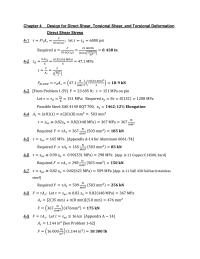
Chapter 4 Design for Direct Shear, Torsional Shear, and Torsional Deformation Direct Shear Stress 4-1 4-4 4-5 . 4-6 4-7 4-8 4-9 4-2 4-3 [ 4-10 4-13 : 4-14 4-15 : 4-16 = 25 mm F2 cos 10° F2 sin […]
Chapter 4 Torsion of Noncircular Sections
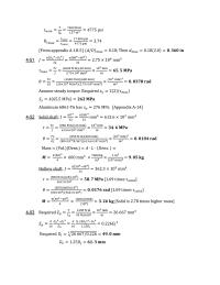
4-51 4-52 4-53 4-56 4-57 4-58 4-59 4-60 4-54 ; 4-55 ; 4-61 4-64 4-65 4-66 4-67 4-68 4-69 4-62 4-63 4-71 4-72 4-73 4-74 4-70 ; ; 1 ; 4.76 4-77 4-78 4-75 ; ; [ 4-79 Torsion of […]
Chapter 5 Also moment at ends of simple beam
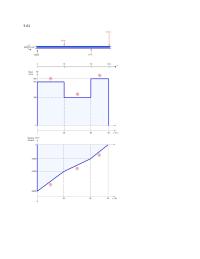
5-106 5-107 5-108 5-109 5-110 5-111 [Shear force diagram is given.] Forces and reactions on beam: At x = 0: Reaction RA = VA = 35 kN At x = 1.5 m: Force FB = 35 9 = 26 kN […]
Chapter 5 Area Under Shear Curve The V curve From
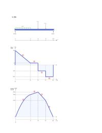
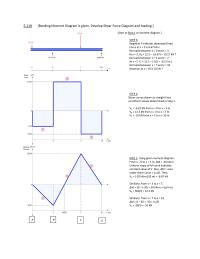
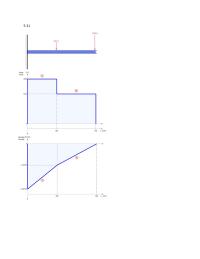
5-119 [Bending Moment Diagram is given. Develop Shear Force Diagram and loading.] [Start at Step 1 at moment diagram.] STEP 3: Negative F indicates downward load. Force at x = 0 is 6.67 kN No loads between x = 0 […]
Chapter 5 Remove the extension arm and replace with
5-1 5-2 5-3 5-4 5-5 5-6 5-7 5-8 5-9 5-10 5-11 5-12 5-13 5-14 5-15 5-16 5-17 5-18 5-19 5-20
Chapter 5 Segment B-C is in tension with a force
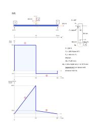
5-81 = 45° FX F = 260 N FY MB F = 260 N FX = (260 N)(cos 45°) FX = 183.4 N = FY Moment : MB = FX(80 mm) MB = (183.4 N)(80 mm) = 14 707 N […]
Chapter 5 This solution is presented in high detail to
5-41 5-42 5-43 5-44 5-45 5-46 5-47 5-48 5-49 5-50 5-51 5-52 5-53 5-54 5-55 5-56 5-57 5-58 5-59 5-60
Chapter 5 CCW moment to keep it in linear and rotational
5-61 5-62 5-63 5-64 5-65 5-66 5-67 5-68 5-69 5-70 5-71 5-72 5-73 5-74 5-75 5-76 5-77 Remove the extension arm and replace with a moment of 120 N-m and an 800-lb force at the right end. 800 lb 800 […]
Chapter 5 The 800 lB force on the vertical arm
5-21 5-22 5-23 5-24 5-25 5-26 5-27 5-28 5-29 5-30 5-31 5-32 5-33 5-34 5-35 5-36 5-37 5-38 5-39 5-40
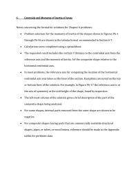
Chapter 6 Reference axis-Centroid by inspection
NOTE: SOLUTIONS FOR RADIUS OF GYRATION PROBLEMS 6-57 TO 6-74 ARE INCLUDED WITHIN PROBLEMS 6-2 TO 6-29 FIGURE P6-1 Units: Inches NOTE: L-shape Part Area y Ay IcdAd 2 Ic + Ad2 1-Vertical 0.5000 1.0000 0.5000 0.1667 0.3365 0.0566 0.2233 […]
Chapter 7 Maximum permissible load on beam
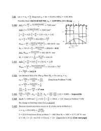
7-99 , 7-100 7-101 0 7-102 7-103 7-104 [ 7-105 F F V M M C = 150 F MB = 75 F 7-106 ; A B C D E 2P V 0 M 0 7-107 ; , Point on […]
Chapter 7 To specify the lightest standard hollow
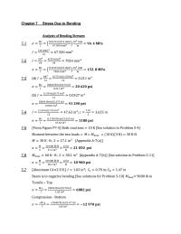
Chapter 7 Stress Due to Bending 7-1 7-4 7-5 7-6 7-7 = 7-2 7-3 (a) (b) 7-8 7-9 7-10 ; = 7-11 6 in 7-12 ; 7-13 Required ; 7-14 ; ] 12 in 7-15 7-16 7-17 7-18 OK 7-19 […]
Chapter 8 Stress distribution symmetrical about
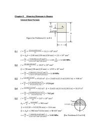
Chapter 8 Shearing Stresses in Beams h/2 Ap 8-1 8-2 8-3 8-4 8-5 [ Ap 0.212(D) = y y=h/4 h t 8-6 ; 8-7 8-8 8-9 0.90 in 1.5 in 0.375 in X 8-10 0.75 in 6 in 1 in […]
Chapter 9 Moment-Area Method Maximum negative
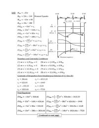
9-83 (5) (6) (7) (8) : V (kN) 0 20 kN 30 kN 20 kN RB = 40 kN RD = 30 kN Maximum negative y M 20 (kN m) 0 EI (kN m2) 0 EIy (kN m3) 0 Max. […]
Chapter 9 Statically Indeterminate Beams Superposition
9-59 9-60 9-61 , . 9-62 W = wL = 12(40) = 480 lb 140 lb w = 12 lb/in 20 in 20 in P = 180 lb [ [ 8 in 12 lb/in I 20 kN/m 20 kN/m RB […]
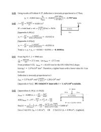
Chapter 9 Note that a higher I may be required
Chapter 9 Deflection of Beams 9-1 [ 9-4 9-5 9-6 [ 9-7 9-8 9-2 9-3 [ 9-9 9-10 9-11 9-12 [ 9-13 9-14 9-15 3.0 kN 9-16 9-17 0.100 in 1.5 kN 1.5 kN 350 mm 250 mm b t […]