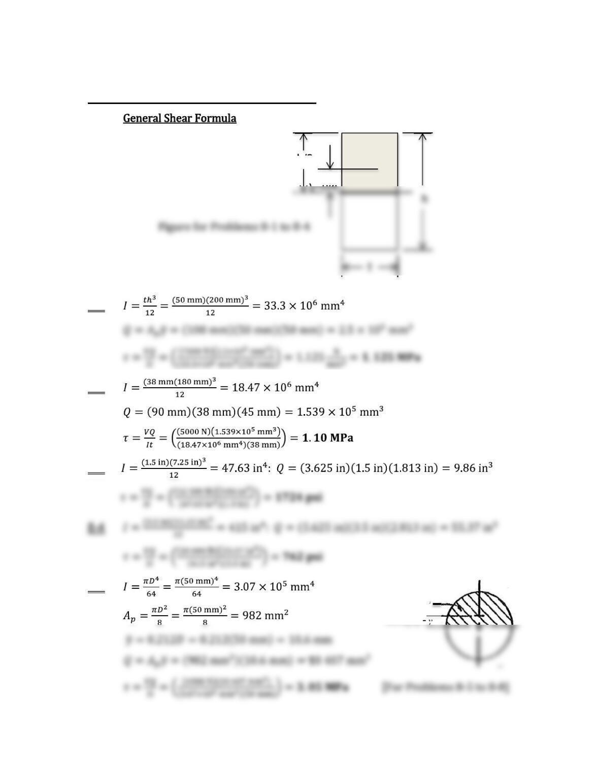
Chapter 8 Shearing Stresses in Beams
h/2 Ap
8-1
8-2
8-3
8-5
Ap
0.212(D) = y
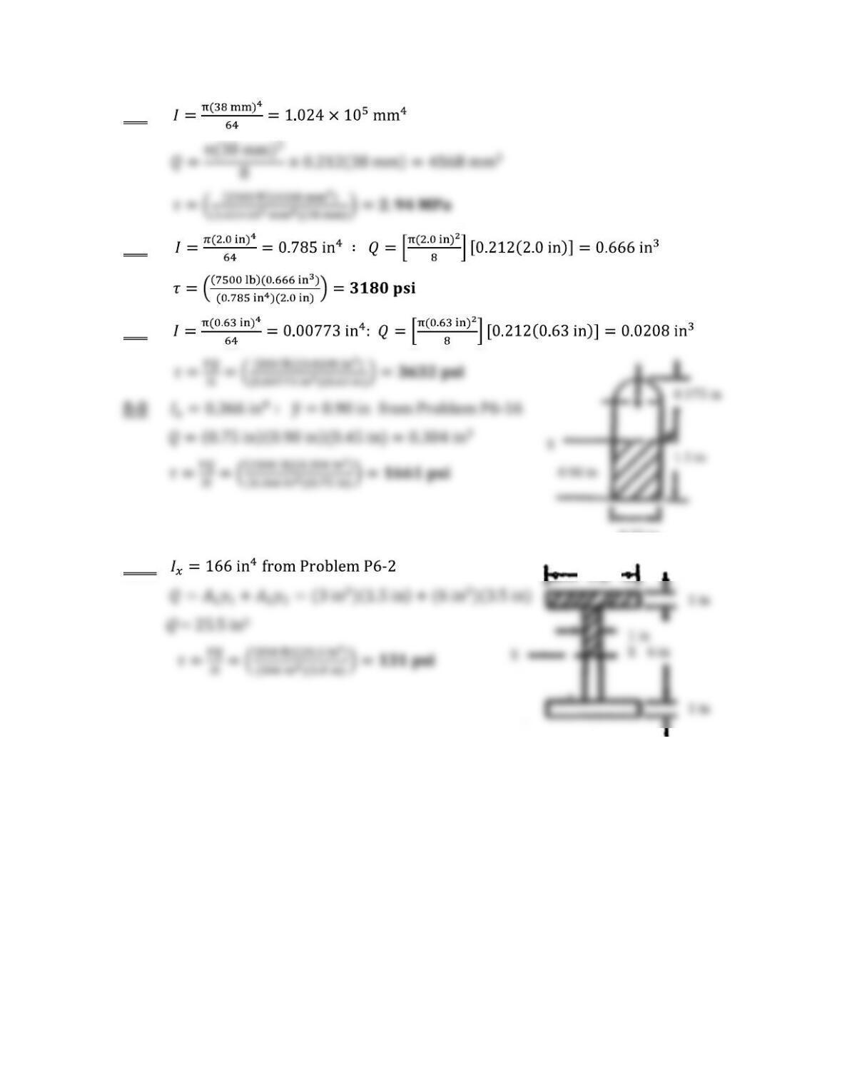
8-6 ;
8-7
8-8
8-10
0.75 in
6 in
2
1
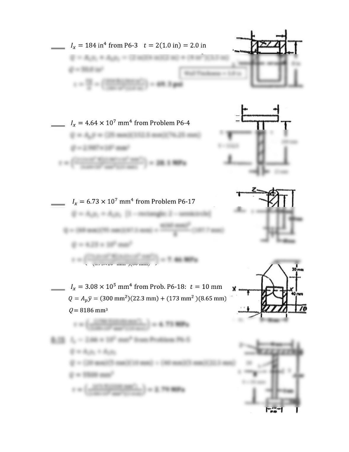
8-11 :
8-12
X
8-13
8-14
25 mm
175 mm
y2 = 107.2 mm
Y = 27.3
A2
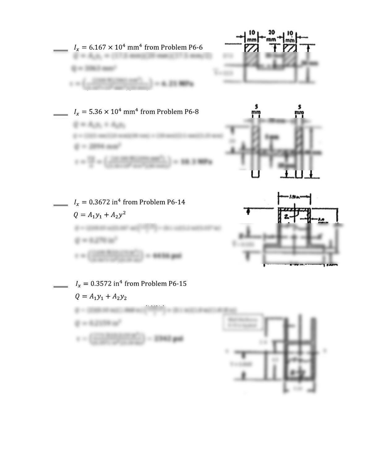
8-16
8-17
8-18
8-19
2.5
1.167
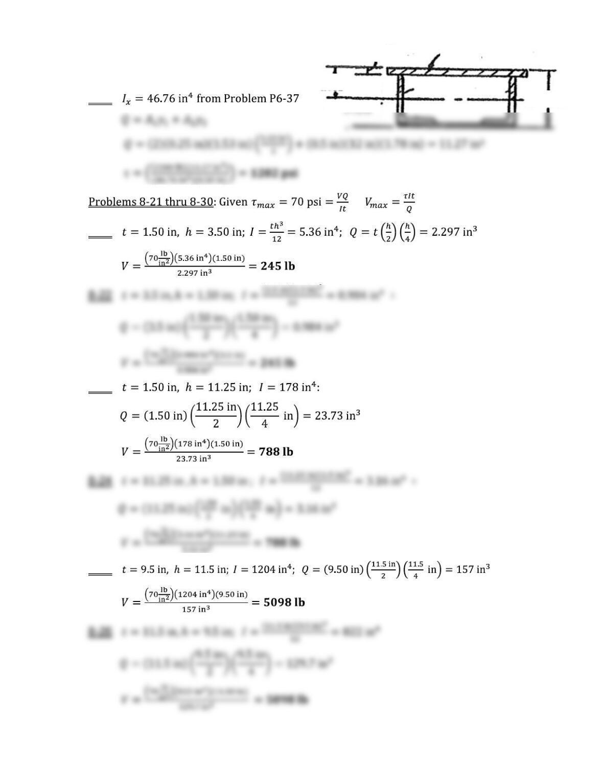
8-20
8-21
8-23
8-25
2.03
1.53
0.50 ½ × 12
4.75
L4×3×1/4
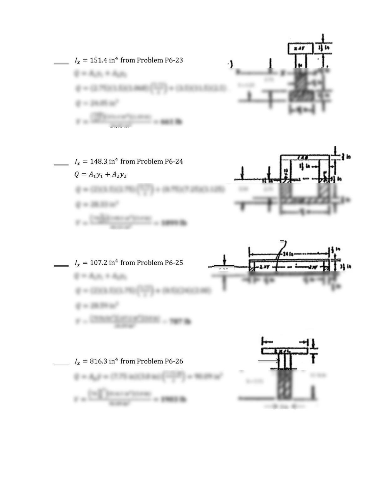
X
½ × 24 plywood
8-27
8-28
8-29
8-30
X
11 ¼ in
1 ½ in
2×12 wood board
Two 2×12
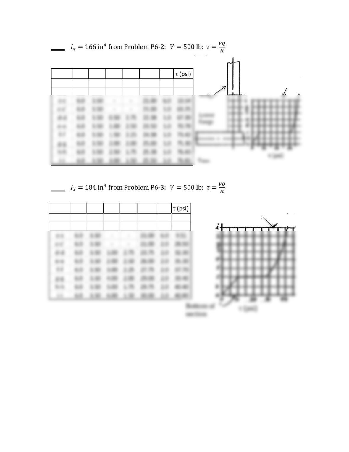
8-31
8-32
Section A1y1A2y2Q t
a-a 0.0 – – – 0.0 6.0 0.00
b-b 3.0 3.75 – – 11.25 6.0 5.65
Section A1y1A2y2Q t
a-a 0.0 – – – 0.0 6.0 0.00
b-b 3.0 3.75 – – 11.25 6.0 5.10
Stress distribution
symmetrical about
neutral axis
Stress distribution
symmetrical about
neutral axis
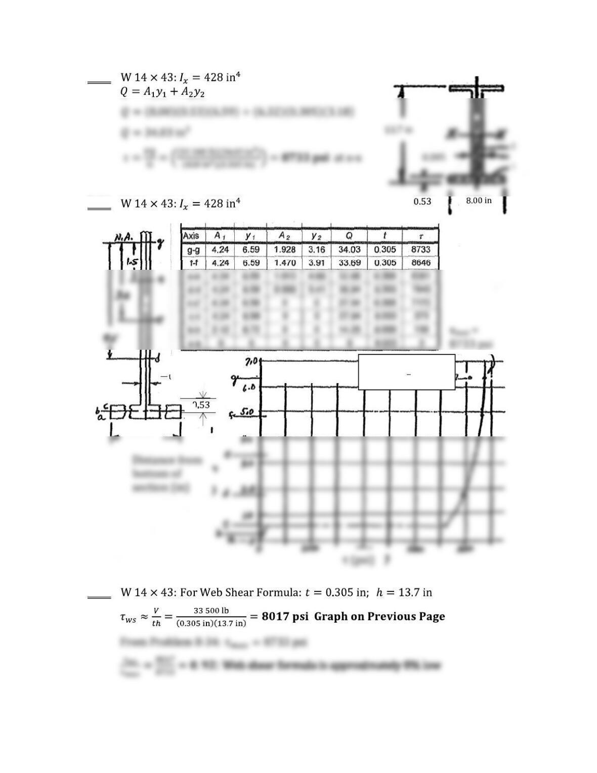
8-33
8-34
8-35
7.995
0.53
0.305
Problem 8
–
35
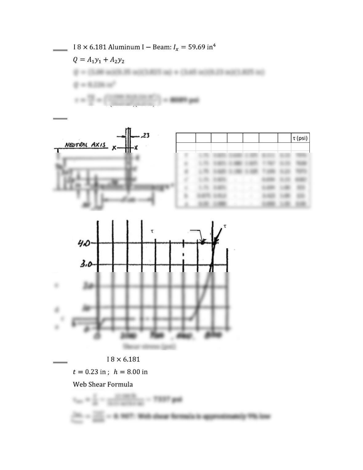
web shear 8017 psi
Neutral axis
8-36
8-37
8-38 Aluminum
Section A1y1A2y2Q t
x–x 1.75 3.825 0.840 1.825 8.266 0.23 8089
max = 8089 psi
Web shear
max = 7337 psi
X-X
f
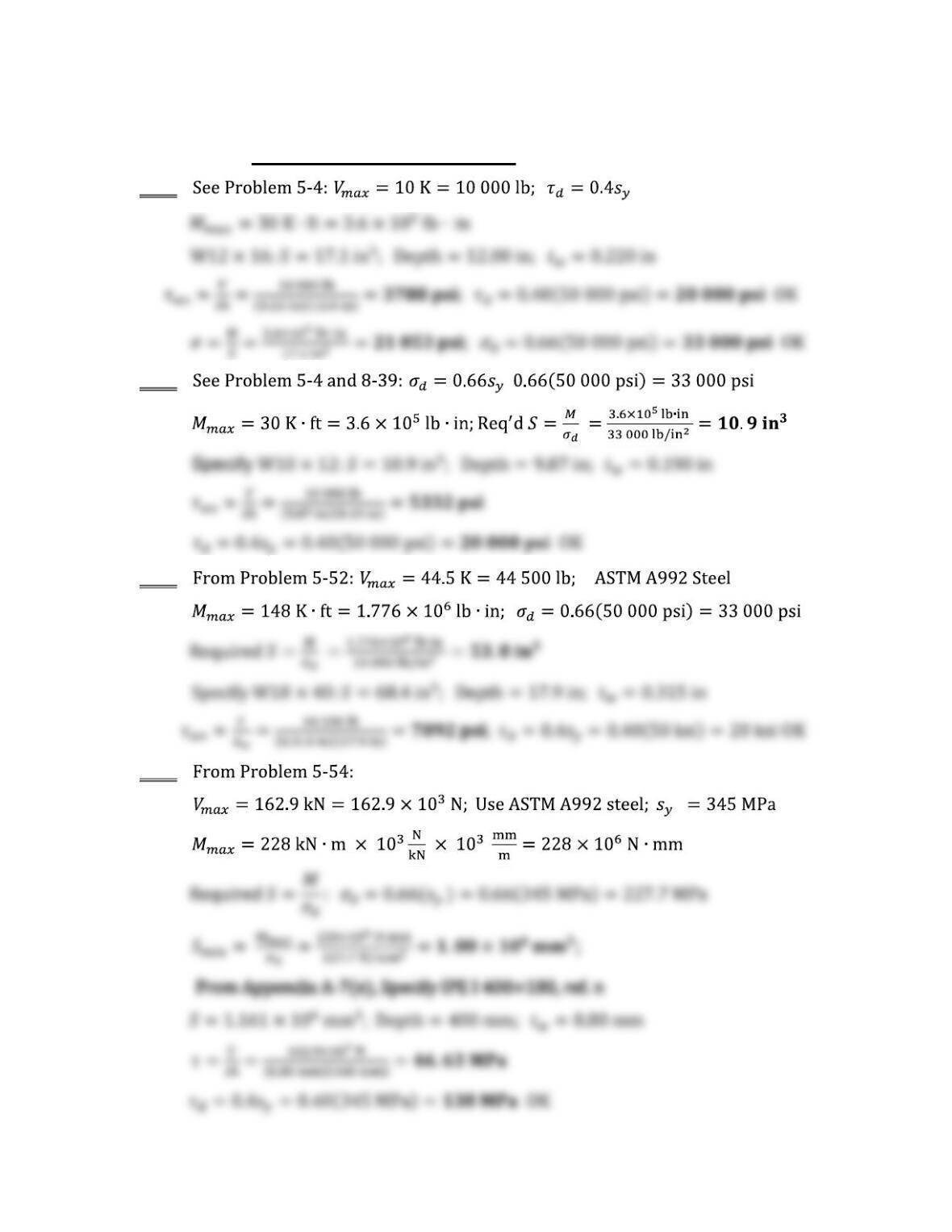
Use of Design Shear Stresses
8-39
8-40
8-41
8-42
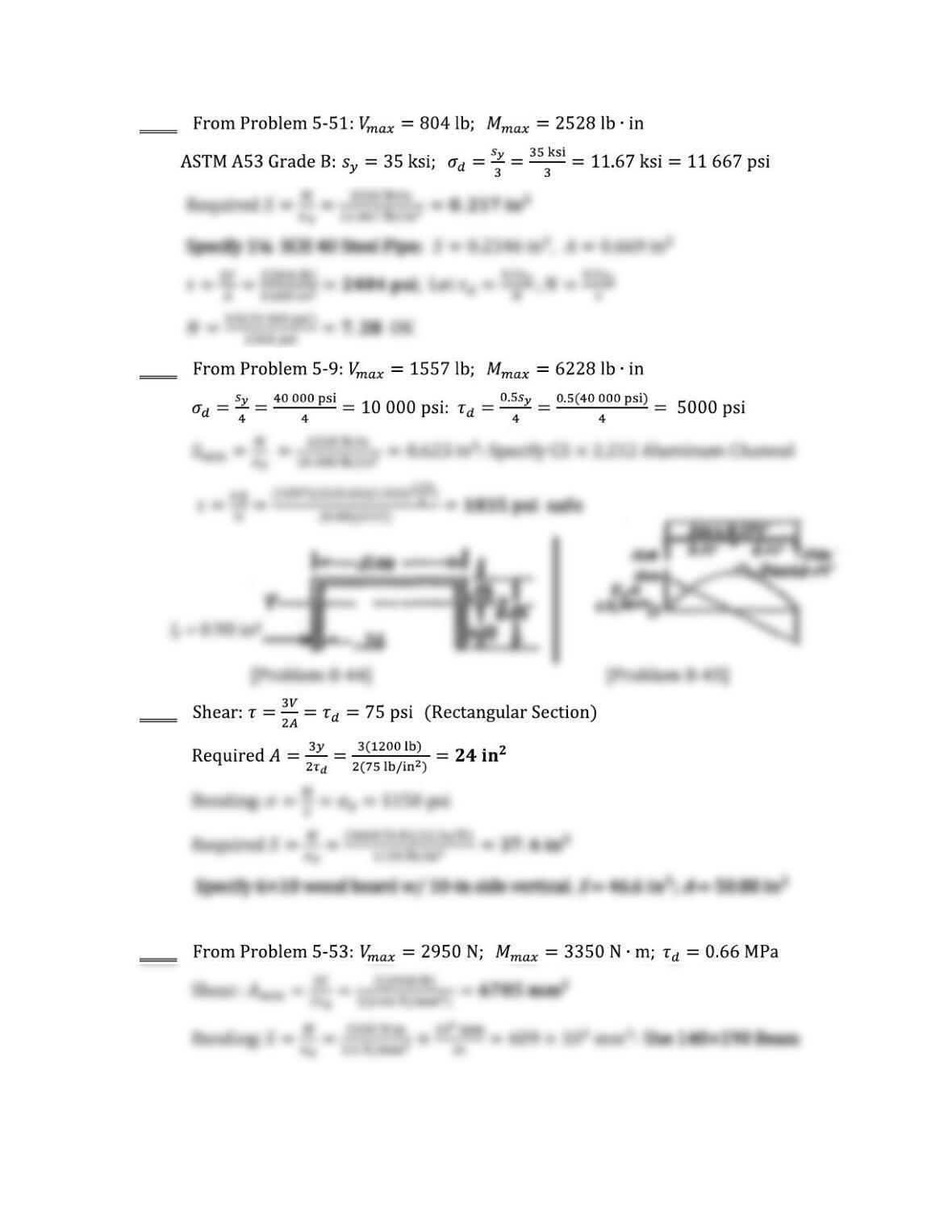
8-43
8-44
8-45
8-46
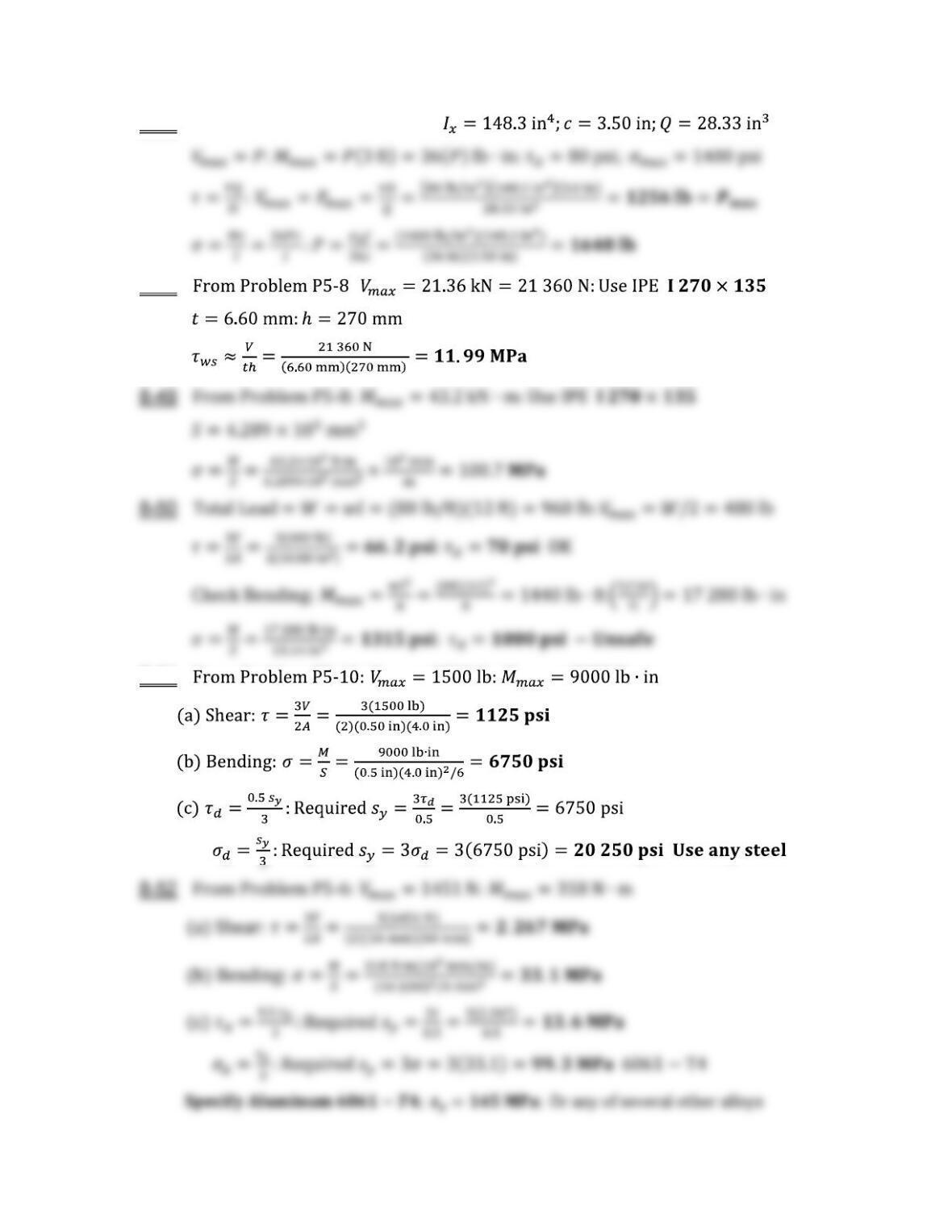
8-47 From Problems 6-24 and 8-28:
8-48 :
8-51
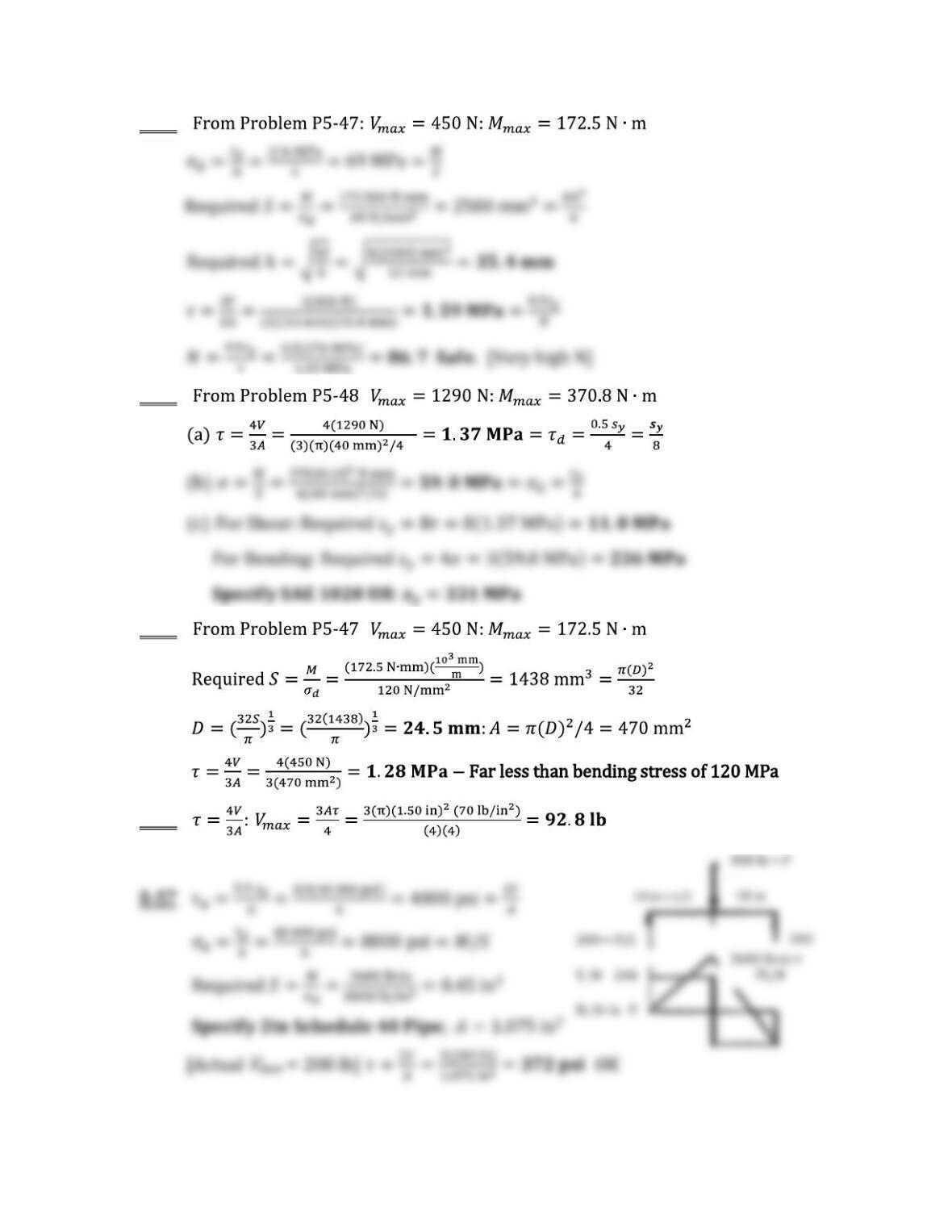
8-53
8-54 :
8-55 :
8-56
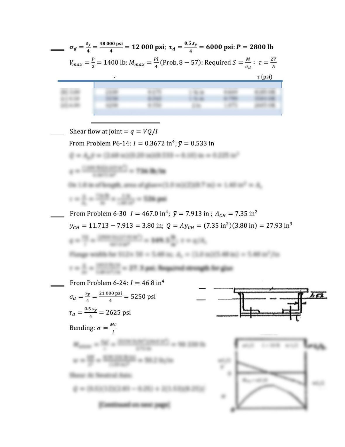
8-58
Length (in) M (lb in) Required S (in3) Pipe size Area (in2)
(a) 1.50 1050 0.0875 1 in 0.494 5668 OK
Shear Flow Problems
8-59
8-60 :
8-61
Y = 2.72 in
1/2×12
2.03
1.53
1/4 × 10
0.25
w (lb/ft)
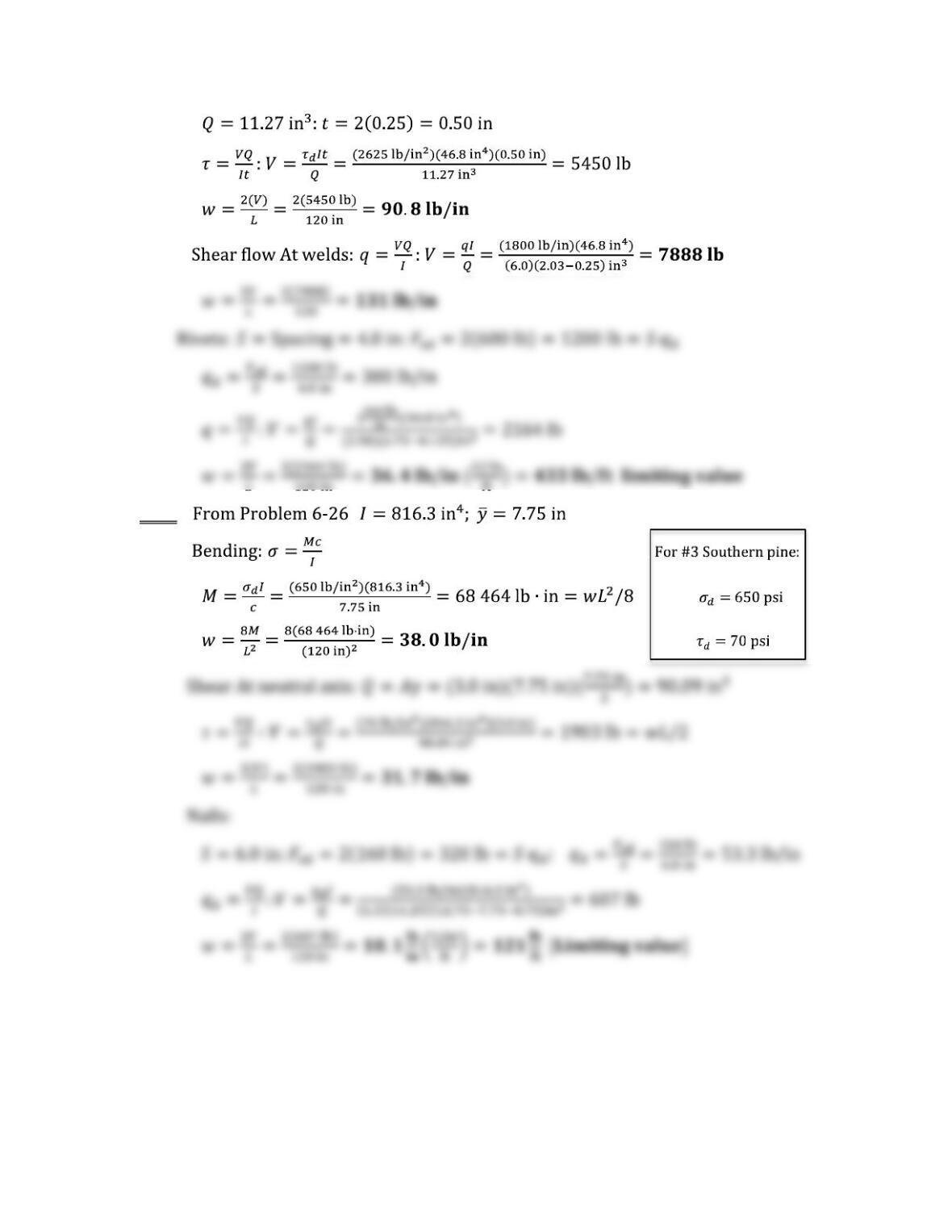
8-62 :
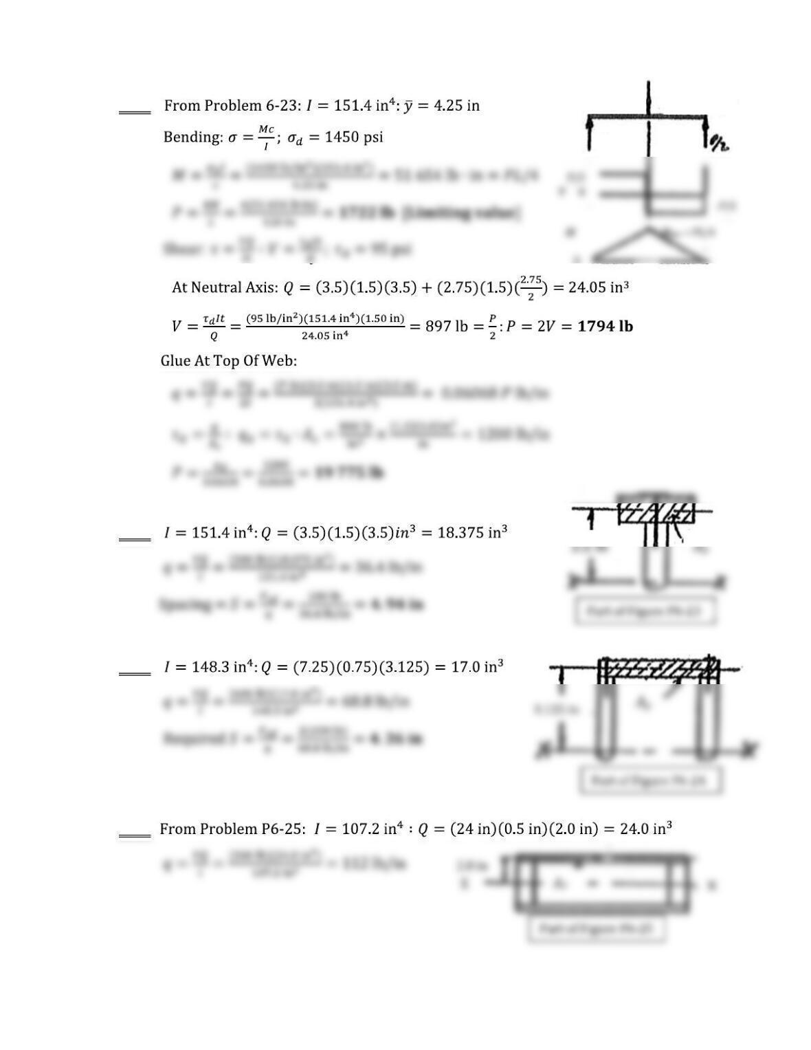
8-63
8-64
8-65
8-66
0
L/2 = 5 ft L/2
P
P/2
P
/2
M
=
/4
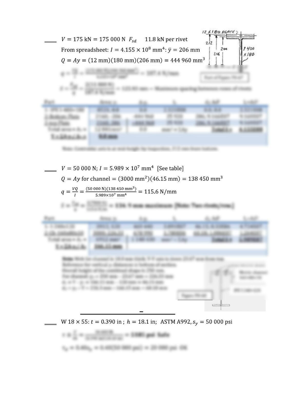
8-67 ; =
8-68
Additional Problems Web Shear
8-69
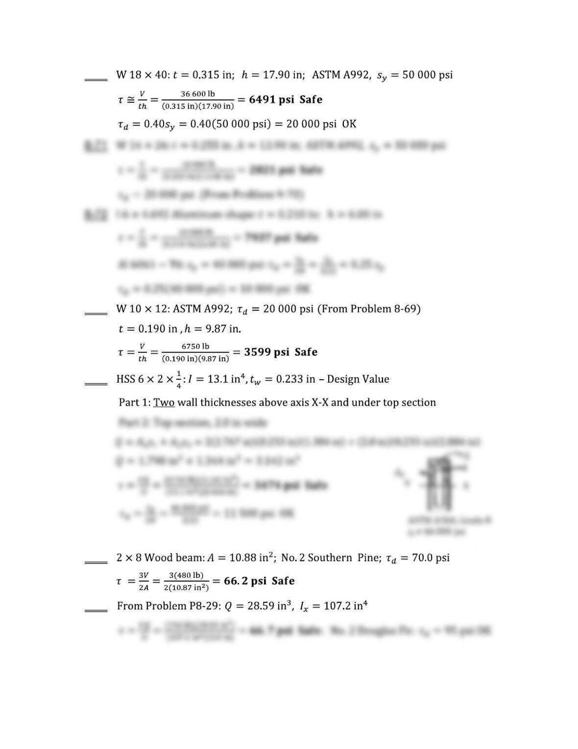
8-70
8-73
8-74
8-75
8-76
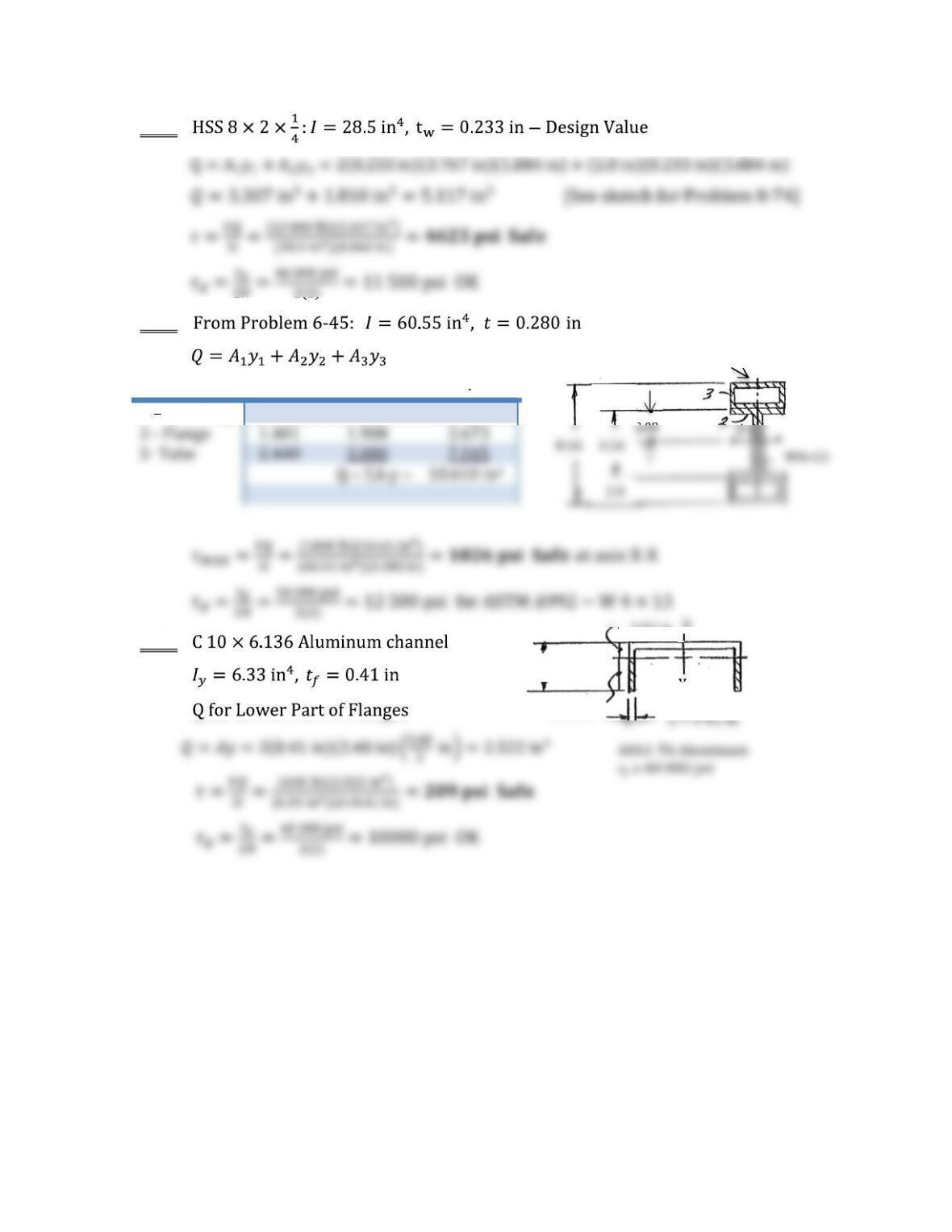
8-77
8-78
Part Area, A y A y
1 Web only 0.486 0.868 0.422
8-79
HSS4×2×1/4
2.0
2.48 in
3.50 in
1.02 in
Y
Y
X
X
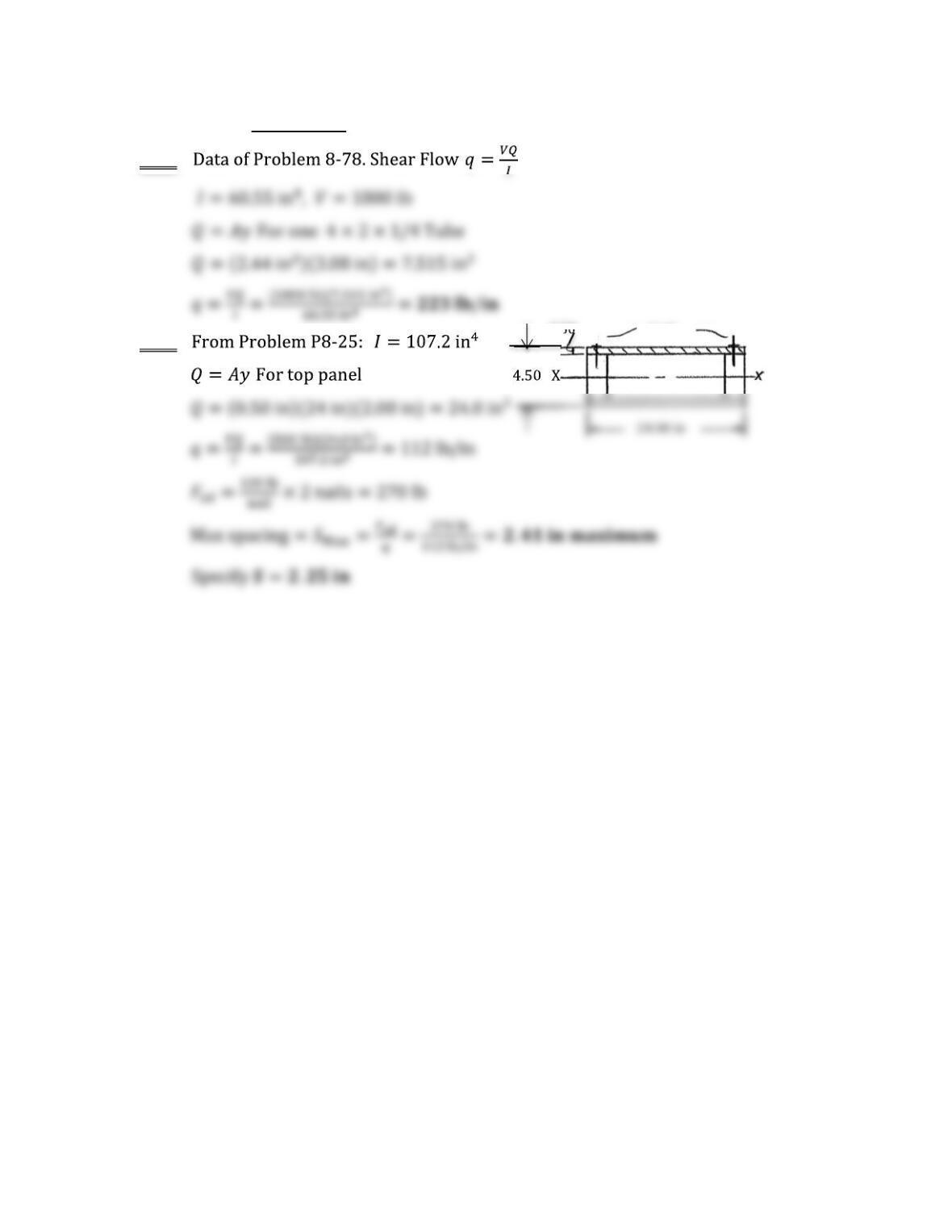
Shear Flow
8-80
8-81
24.00 in
Nails
0.50