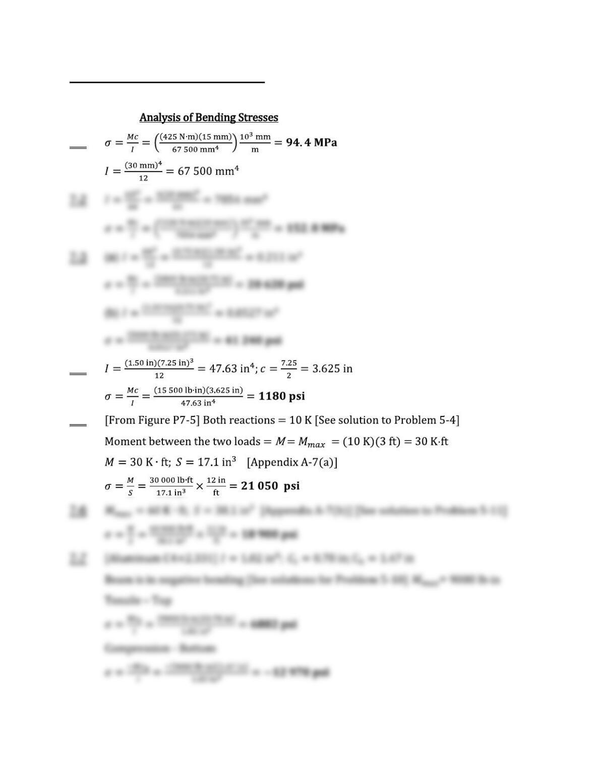
Chapter 7 Stress Due to Bending
7-1
7-4
7-5
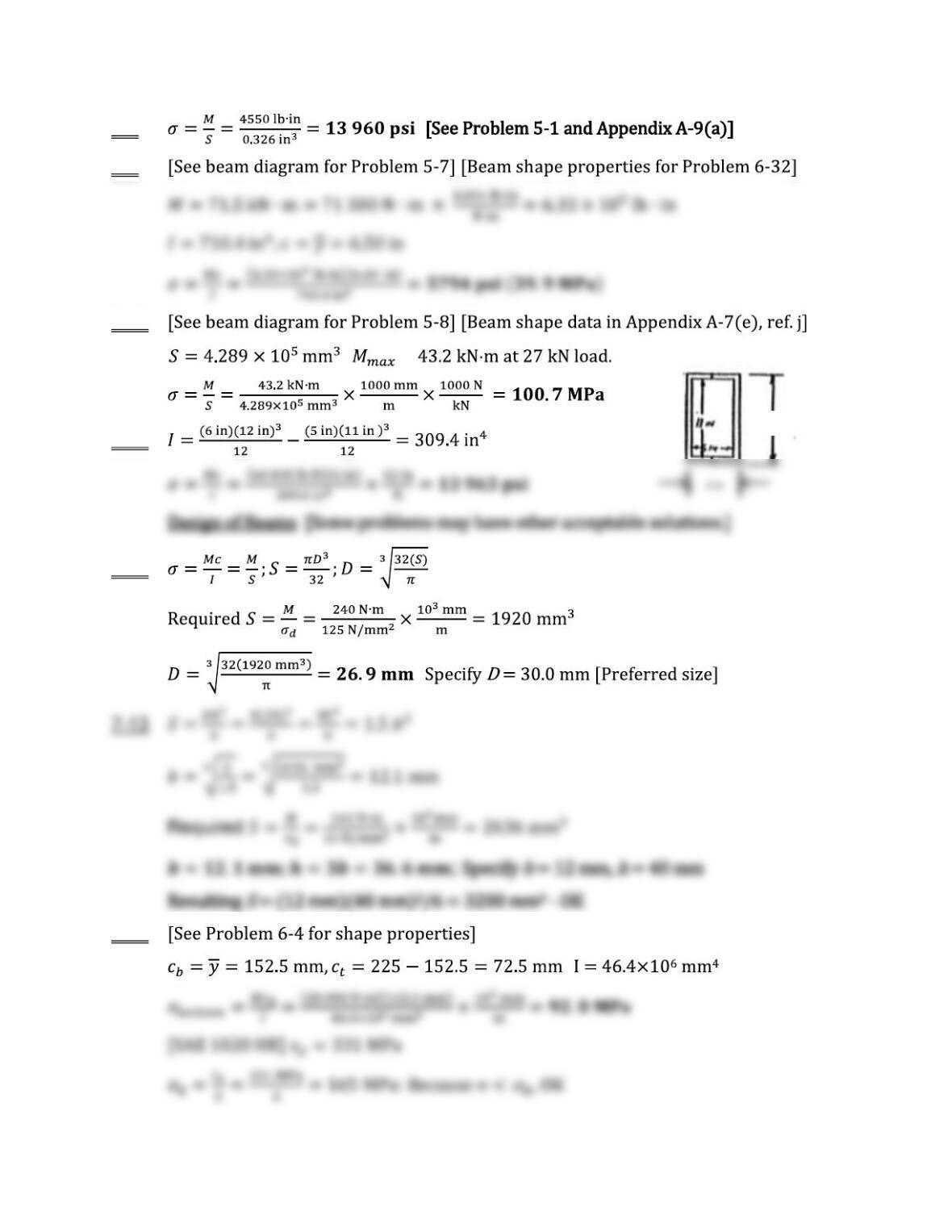
7-8
7-9
7-10
; =
7-11
6 in
7-12
;
7-14
;
12 in
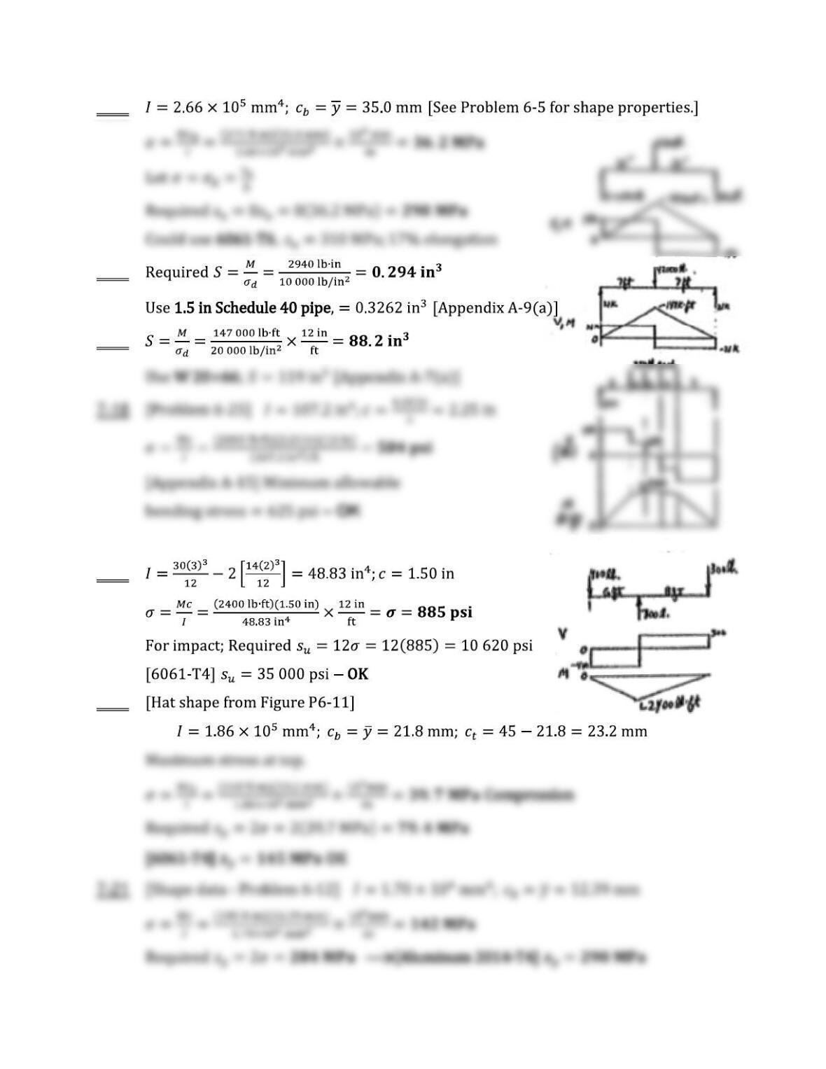
7-15
7-16
7-17
7-19
7-20
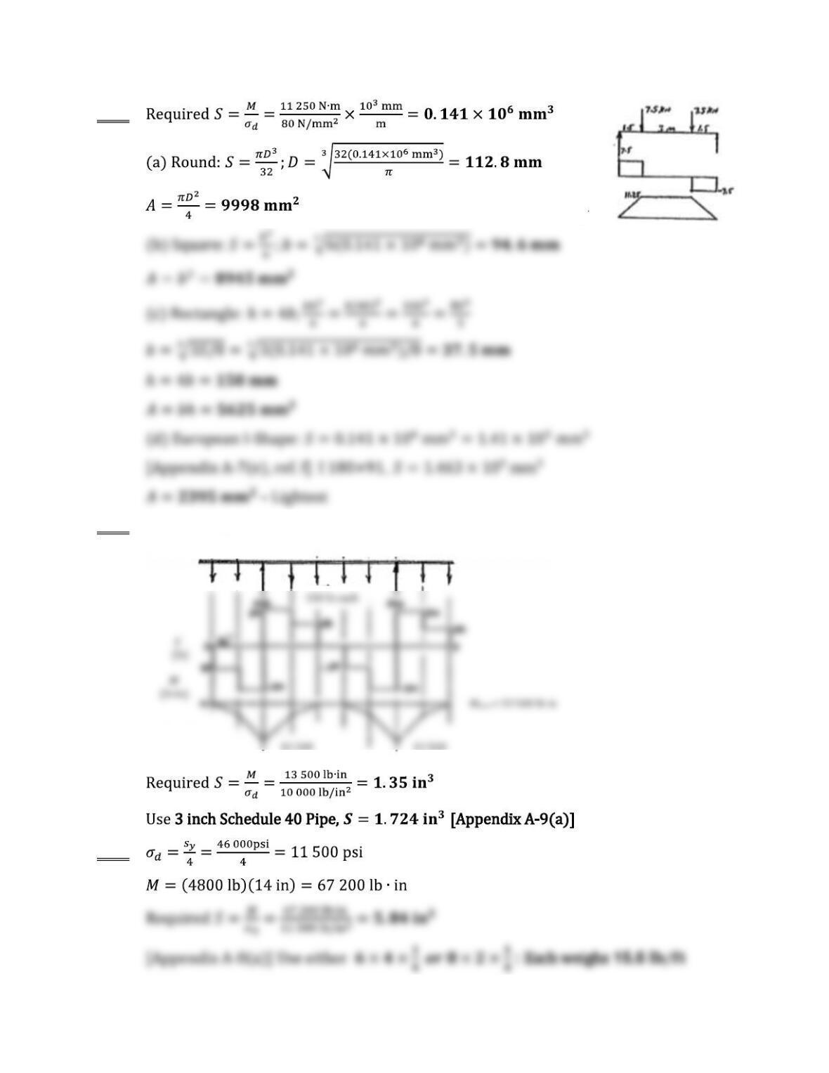
7-22
7-23
7-24
V
(kN)
M
(kN m)
30 in Spacing-Typical
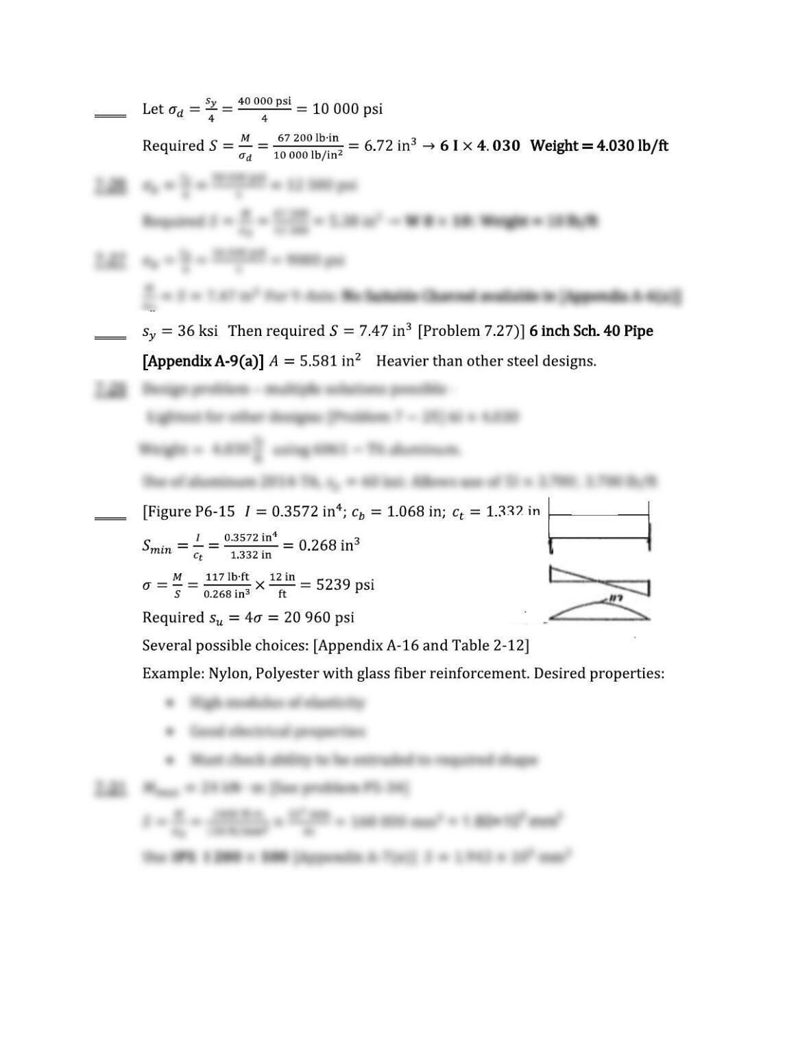
7-25
:
7-28 –
–
7-30 ]
V
(lb)
M
(lb ft)
6.5 lb/ft
R = 39 lb
12.0 ft
Mmax = 117 lb ft
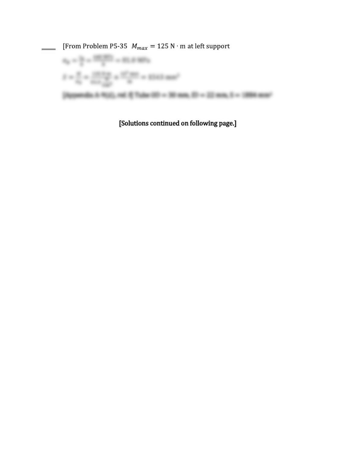
7-32 ]
7-33 Specify the lightest wide–flange beam. ASTM A992 structural steel. Yield strength = 50 ksi
7-34M Specify the lightest European IPE I-shape. ASTM A992 structural steel. sy = 345 MPa
Design stress: d = 0.66 sy = (0.66)(345 MPa) = 227.7 MPa = 227.7 N/mm2
Problems 7-35 to 7-42 are similar to 7-33 and 7-34 above with the same design stress. Maximum
bending moment varies with the beam loading shown in the indicated figures from Chapter 5.
For data in metric units, indicated by “M“, specify SI rectangular tube from App. A-8©
Problems 7-43 to 7-52 use the same set of beam loadings as 7-33 and 7-34 but the objective is
Problems 7-53 to 7-62 use the same set of beam loadings as 7-33 and 7-42 but the material is
ASTM A572 Grade 60 with sy = 60 ksi (414 MPa). Then,
specify European IPE I-shape for metric units.
ASTM A5762 Gr. 60
Prob. Fig. Mmax Req’d. Lightest Prob. Lightest Prob. Req’d. Lightest
No. No. SW or IPE-beam No. Rect. Tube No. SW or IPE-beam
7-33 P5-3 45.7 K-ft 16.6 in
3
W12x16 7-43 8x8x1/4 7-53 13.8 in
3
W12x16
7-34M P5-7 71.5 kN-m 3.14×10
5
mm
3
IPE 240×120 7-44M 250x250x8 7-54M 2.62x10
5
mm
3
IPE 240×120
sy = 60 ksi (414 MPa)ASTM A992; sy = 50 ksi (345 MPa)
The results for these three sets of problems are summarized below.
5
3
5
3
3
3
5
3
5
3
3
3
3
3
3
3
3
3
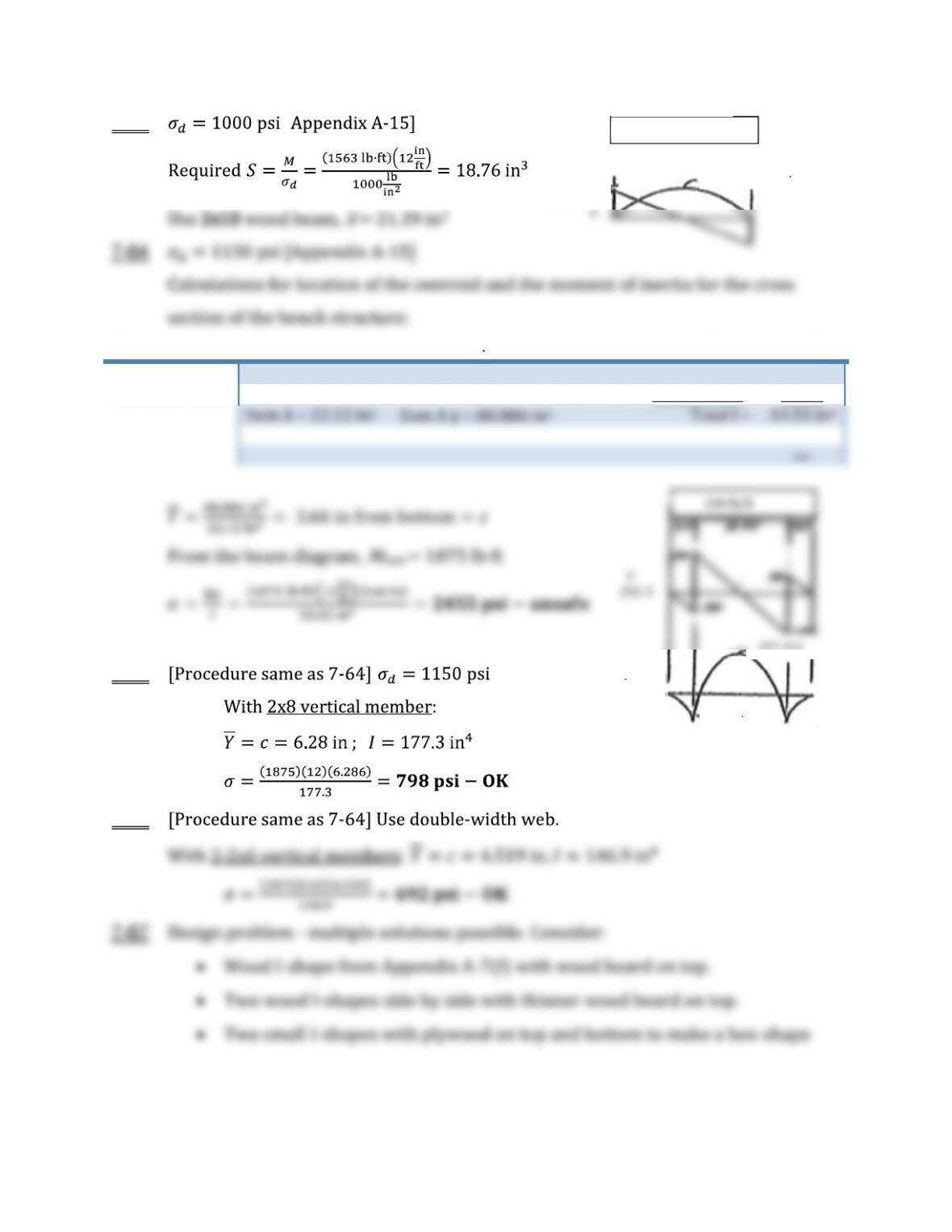
7-63 [
Part A; y A y I d; Ad2 I+Ad2
Vertical 2×4 5.25; 1.75 9.188 5.36 1.907; 19.085 24.445
Horizontal 2×12
16.875; 4,25 71.798 3.164 0.593; 5.939 9.103
7-65
7-66
125 lb/ft
Length = 10 ft
Mmax = 1563 lb ft
625
V, M
R
A
= R
B
= 625 lb
M
(lb ft)
0
1875 lb ft
625 lb ft
7-68
7-69
7-70
:
7-71 :
7-72
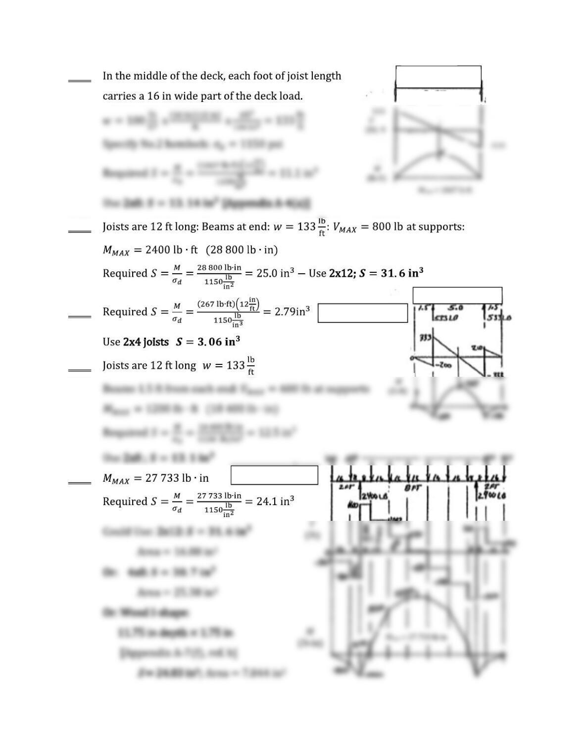
w = 133 lb/ft
W = 1067 lb
533 8 ft 533
w = 133 lb/ft
V
(lb)
Diagram for 7-70
Diagram for 7-72
Design Problem
7-73
7-74
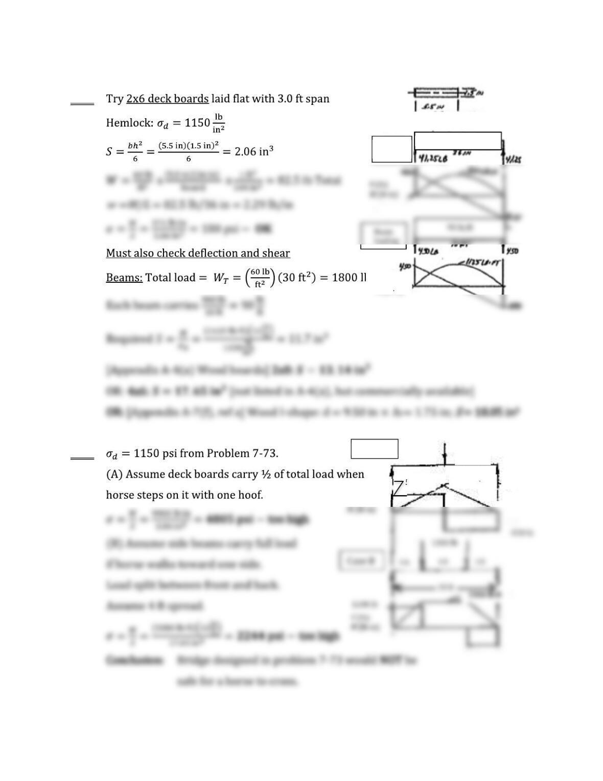
Cross section of board
w = 2.29 lb/in
Deck
boards
V (lb)
M (lb ft)
V (lb)
18 in
550 lb
1100 lb
Case A
18 in
550 lb
9900 lb in
90 lb/ft
7-75 –
7-76
7-77 ;
=
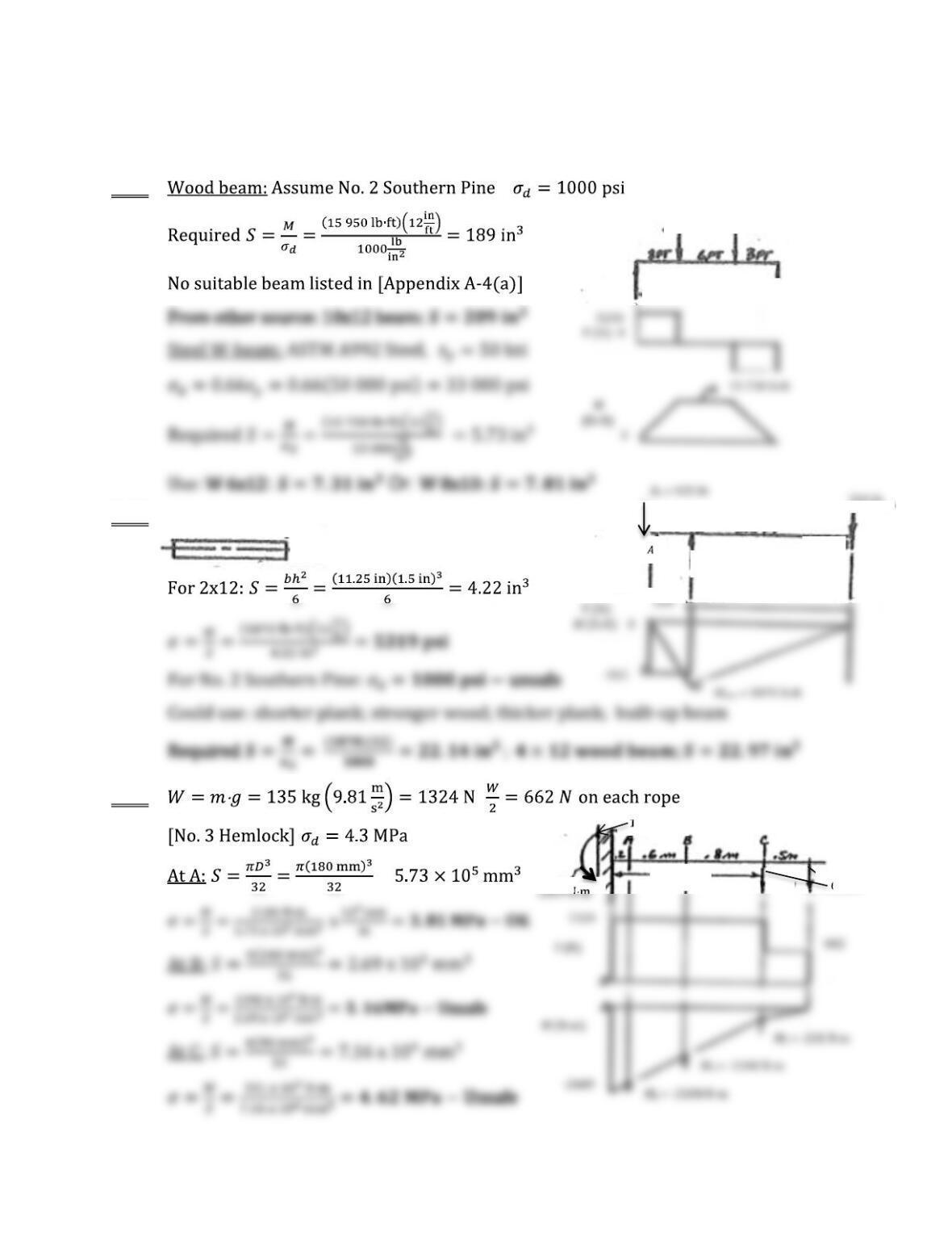
Cross section of plank
; 11.25 in×1.5 in
5250 lb
5250 lb
5250 lb 5250 lb
220 lb
RB = 1155 lb
8.5 ft
2 ft
B
A
C
1324 N
1.60 m
7-78
7-79 ]
[
M
7-80 :
;
7-81
800 lb
B
P = 80 lb
A
3.5
w (W = wL)
W/2 = wL/2 wL/2
wL
/2
V
L = 800 mm
Cross section: 3.5×1.5 in
80 in
C
8
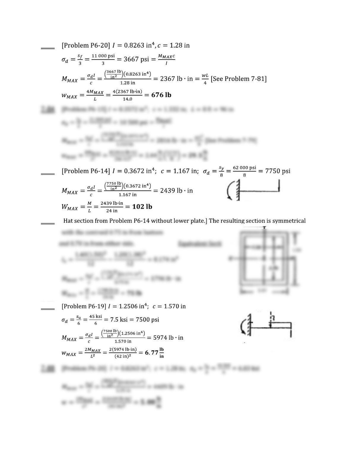
7-83
7-85
7-86 [
7-87
L
= 24 in
Mmax = WL
W
Mmax = WL/2 = wL2/2
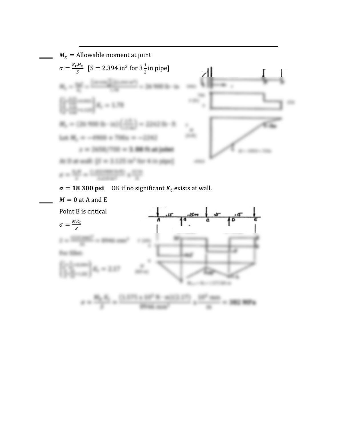
L = 42 in
W = wL L/
2
Beams with Stress Concentrations and Varying Cross Sections
7-89
–
7-90
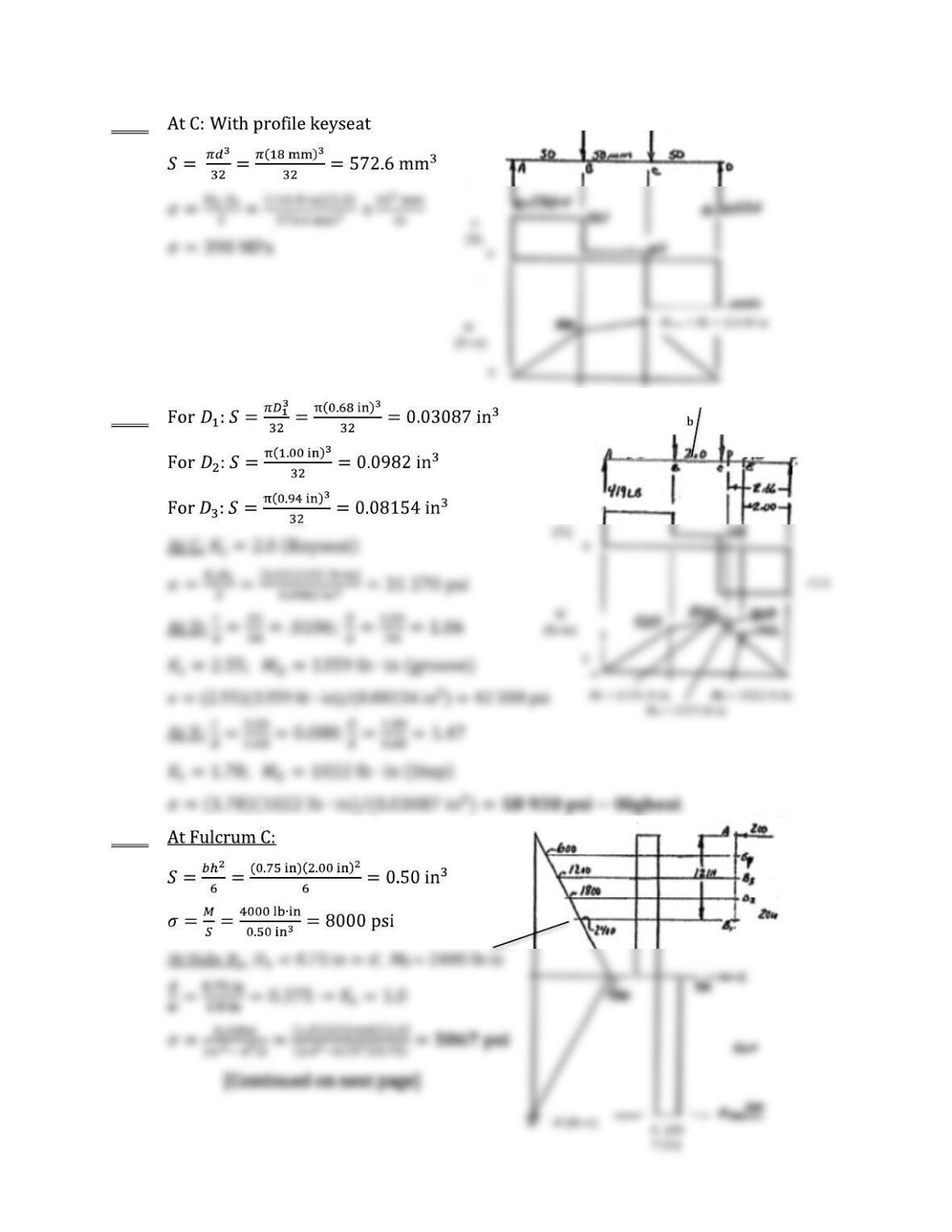
700
6 ft
350 350
2 ft
10.5 kN 12.5 kN 8.0 kN
R = 18 kN R = 13 kN
=
–
4900 + 700
7-91
7-92
7-93
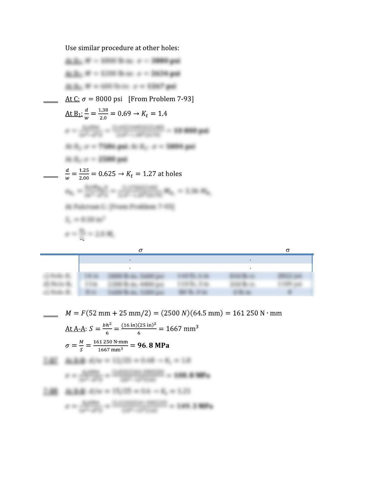
1250 N 2800 N
280 lb
650 lb
419
V
3.0 in 3.0 in
2.0
511
7-94
0
7-95
Pivot CD MC; C RA; ABi MBi Bi
a) End hole
20 in 4000 lb in; 8000 psi 200 lb; 12 in 2400 lb in 8064 psi
b) Hole B4 17 in 3400 lb in; 6800 psi 170 lb; 9 in 1530 lb in 5141 psi
7-96