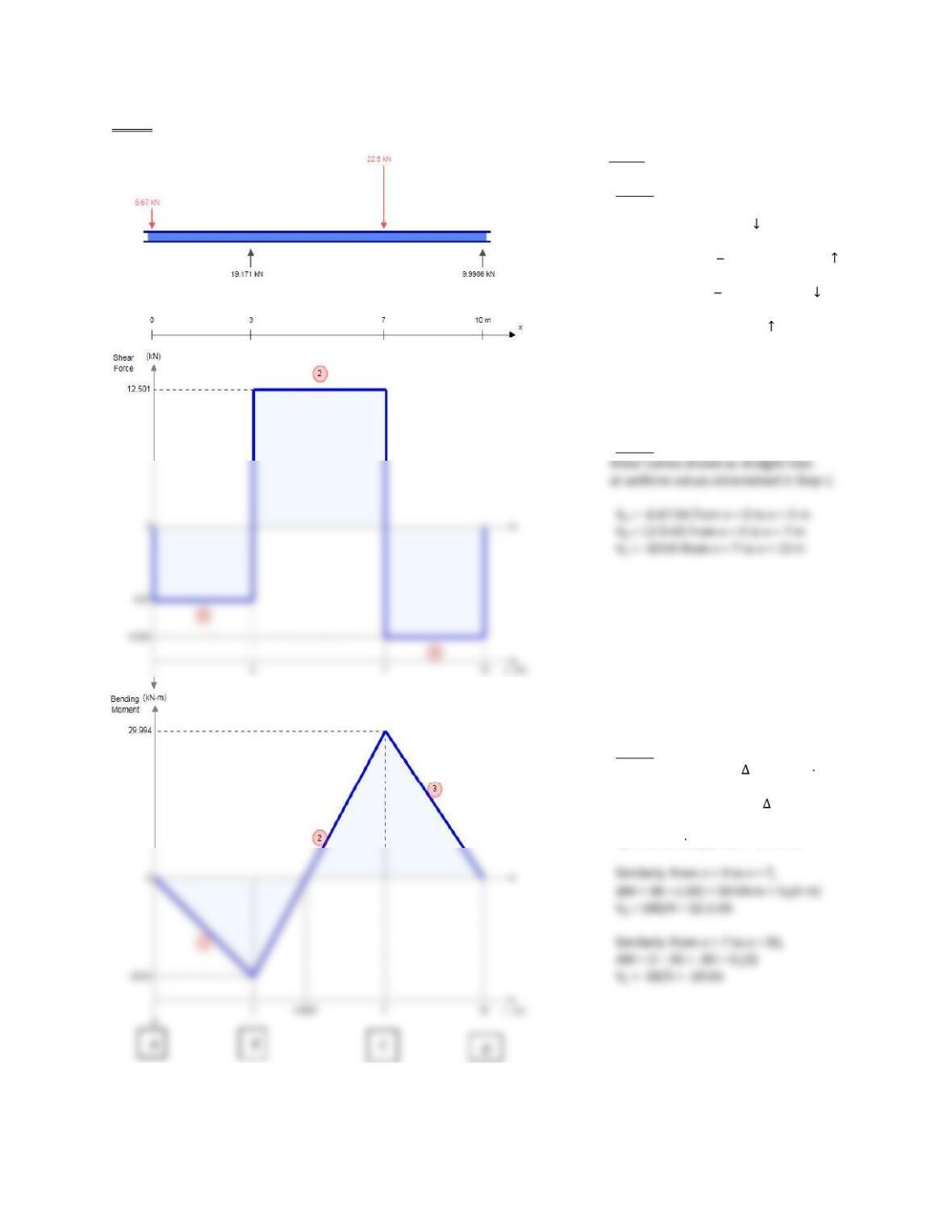
5-119 [Bending Moment Diagram is given. Develop Shear Force Diagram and loading.]
[Start at Step 1 at moment diagram.]
STEP 3:
Negative F indicates downward load.
Force at x = 0 is 6.67 kN
No loads between x = 0 and x = 3.
At x = 3, RB = 12.5 (-6.67) = 19.17 kN
No loads between x = 3 and x = 7
At x =7, FC = 12.5 (-10) = -22.5 kn
No loads between x = 7 and x = 10
Reaction at x = 10 is 10 kN
STEP 2:
STEP 1: Using given moment diagram.
From x = 0 to x = 3 m, M = -20 kN m
Uniform slope of M-curve indicates
constant value of V. Also, M = area
under shear curve = VA(3). Then,
VA = (-20 kN m)/(3 m) = -6.67 kN
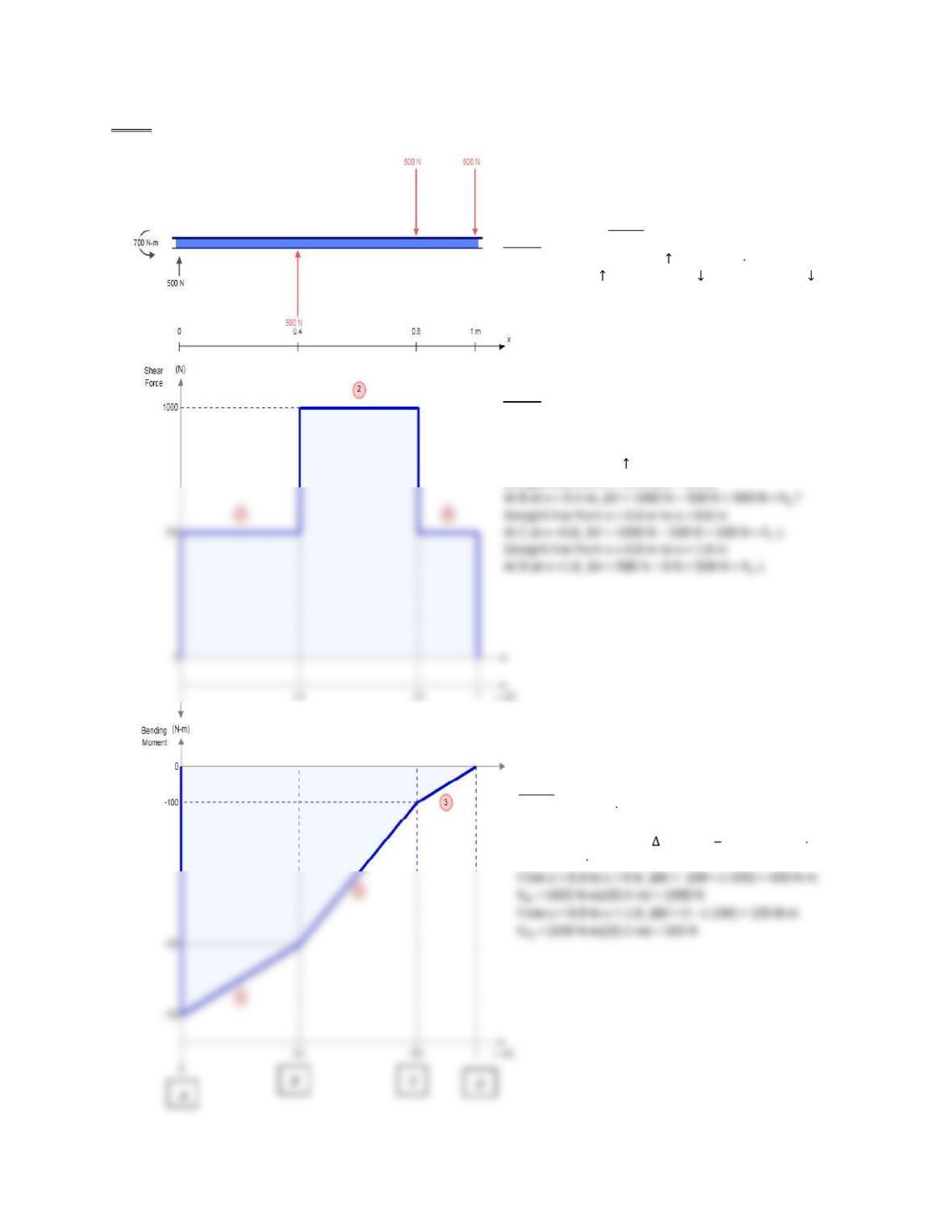
5-120 [Bending Moment Diagram is given. Develop Shear Force Diagram and loading.]
Large negative bending moment at x = 0 indicates
that beam is a cantilever. Straight-line segments
indicate that loading is a series of concentrated loads.
[Start at Step 1 at moment diagram.]
STEP 3:
Reactions at x = : RA = 500 N ; MA = 700 N m CCW
Force FB = 500 N ; Force FC 500 N ; Force FD = 500 N
STEP 2:
Shear curves drawn as straight lines
at uniform values determined in Step 1.
Reaction: RA = 500 N at x = 0
Straight line from x = 0 m to x = 0.4 m
Step 1:
With MA = -700 N m, a counterclockwise moment
of that value exists at the support at x = 0.
From x = 0 to x = 0.4 m, M = -500 (-700) = 200 N m
VAB = (200 N m)/(0.4 m) = 500 N
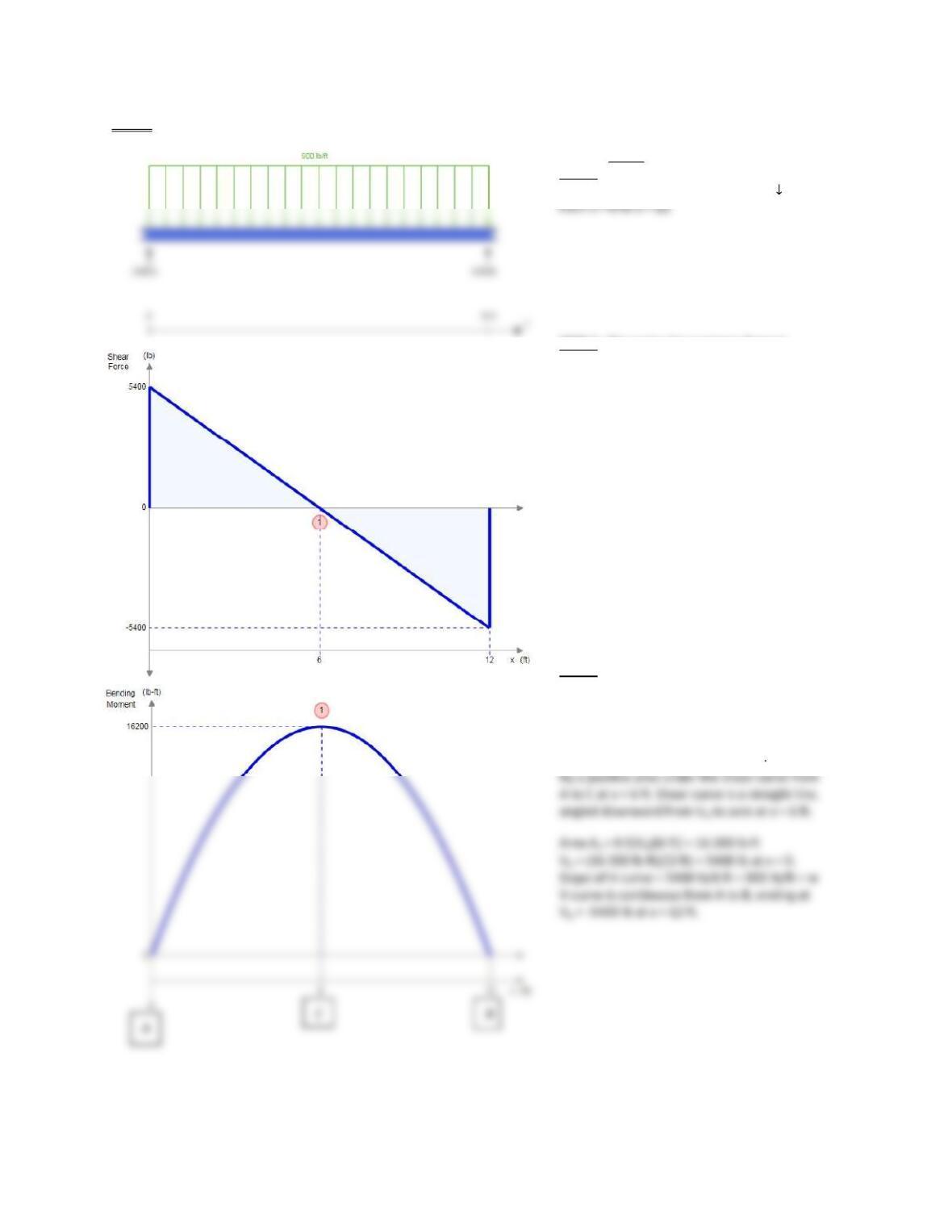
5-121 [Bending Moment Diagram is given. Develop Shear Force Diagram and loading.]
[Start at Step 1 at moment diagram.]
STEP 3: Reactions: RA = RB = 5400 lb
Uniformly distributed load = 900 lb/ft
STEP 2: Discussion for moment diagram
developed the shape shown for the V-curve.
VA = 5400 lb; continuous sloped line at
-900 lb/ft to x = 12 ft; line crosses x-axis at
X = 6 ft where VC = 0; At x = 12, VB = -5400 lb.
STEP 1: Parabolic curve shape indicates that a
uniformly distributed load acts across the entire
length of the beam.
At x = 0, M = 0, indicating a simply supported
Beam. Rise of M from 0 to 16 200 lb ft is caused
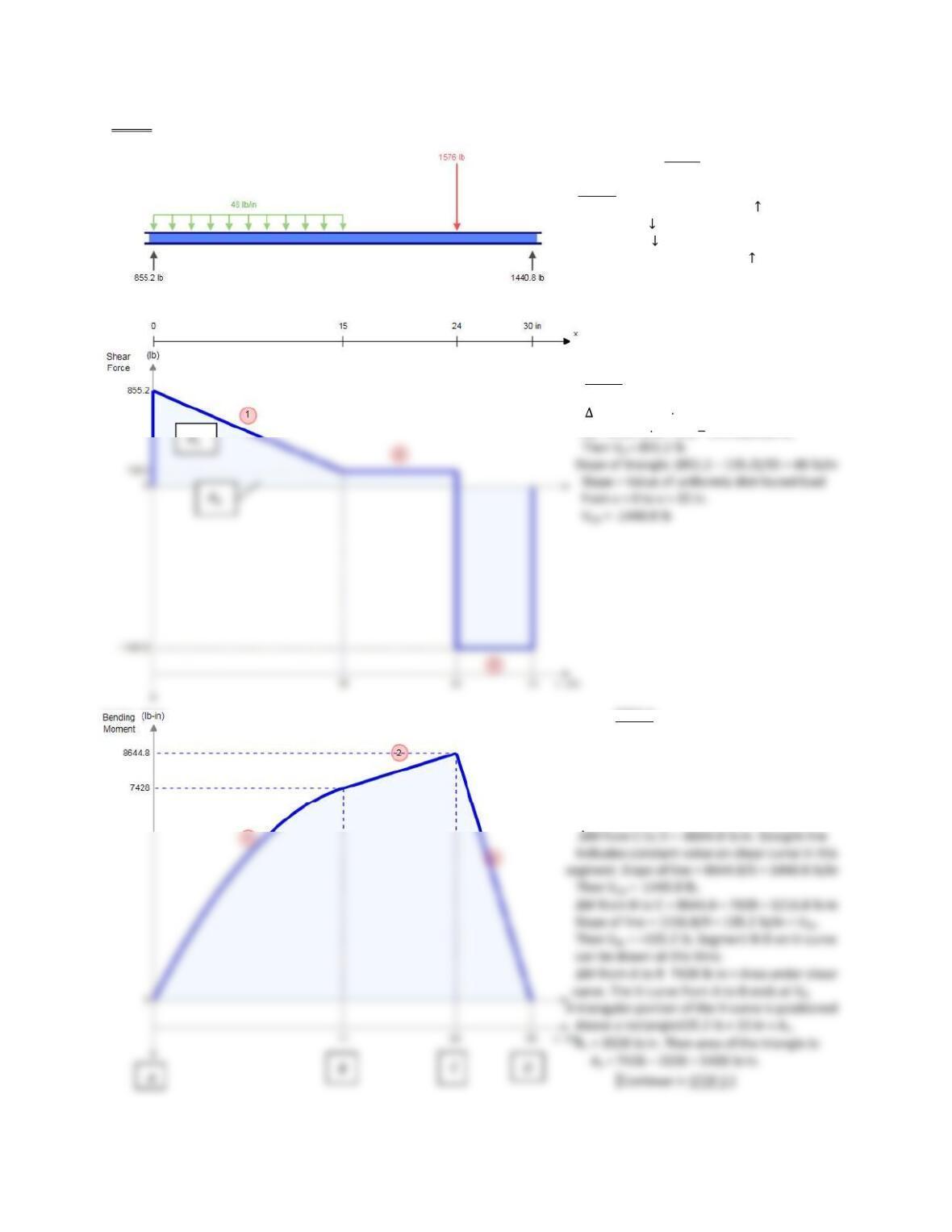
5-122 [Bending Moment Diagram is given. Develop Shear Force Diagram and loading.]
[Start at Step 1 at moment diagram.]
STEP 3: From Steps 2 and 3:
Reaction at x = 0: RA = 855.2 lb
w = 48 lb/in from x = 0 to x = 15 in
FC = 1576 lb at x = 24
Reaction at x = 30 = 1440.8 lb
STEP 2: From STEP 1; VCD = -1440.8 lb
VBC = +135.2 lb.
MAB = 7428 lb in = A1 + A2
A2 = 5400 lb in = (VA 135.2)(15)(0.5)
STEP 1:
Curved shape of M-diagram from x = 0 to
x = 15 in indicates that a uniformly distributed
Load acts over that portion of the beam.
With M = 0 at x = 0 and x = 30 In, beam is
simply supported at its ends. It is more
convenient to work from right to left.
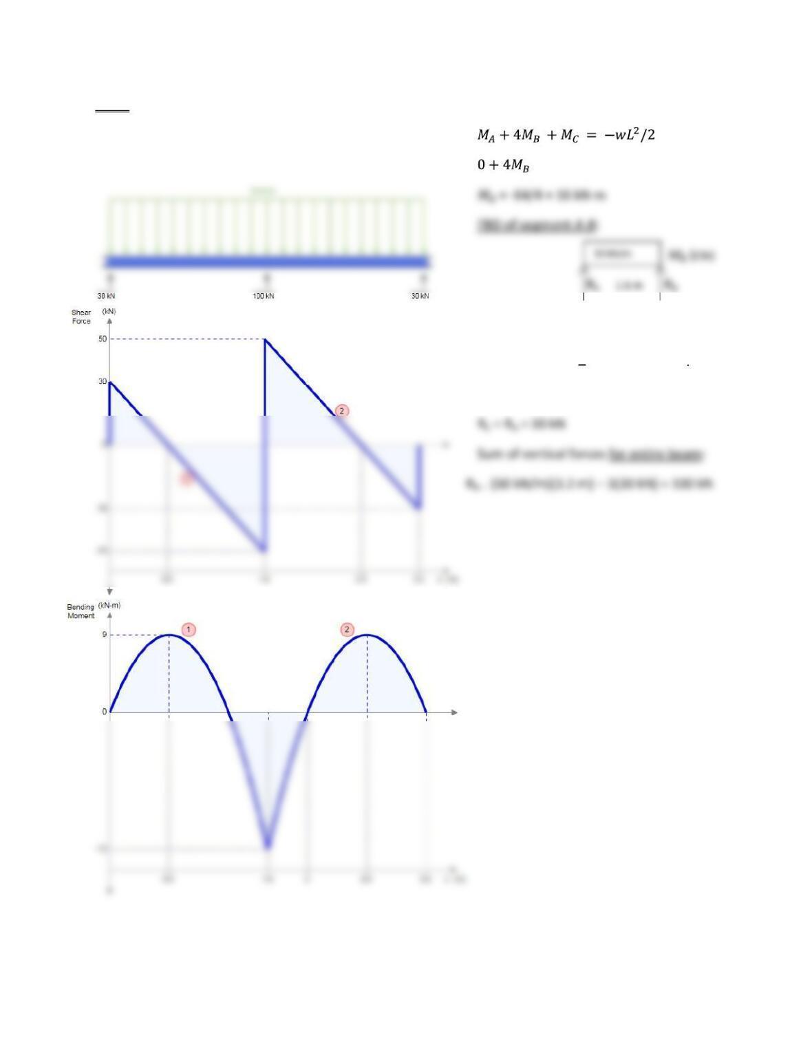
5-123
Use equation 5-6 with MA =Mc +0.
Symmetrical with equal spans of 1.6 m. + 0 = -50(1.6)2 = -64
Sum of moments about B = 0
Resultant of distributed load = 80 kN
0 = 80 kN(0.8 m) RA(1.6 m) -16 kN m
RA = 30 kN; Because of symmetry,
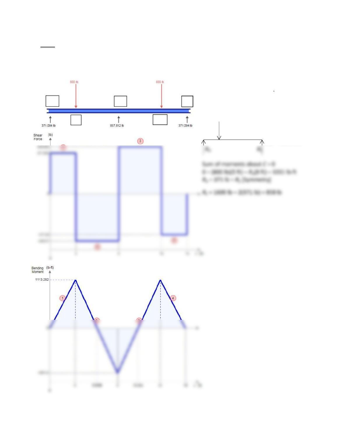
5-124
Use Equation 5-7 with MA = ME = 0. Note: Subscripts in Equation 5-7 are adjusted to match to notation in
Figure P5-124. Symmetrical loading; Equal spans. 0 + 2MC(8+8) + 0 = -800(3)(82-32)/8 -800(3)(82–32)/8
32MC = -33 000
MC = [-33 000]/32 = -1031 lb ft
For Reactions: FBD of Segment A-C
Segment A-C:
3 ft 5 ft
MC = -1031 CW
A
B
C
D
E
373
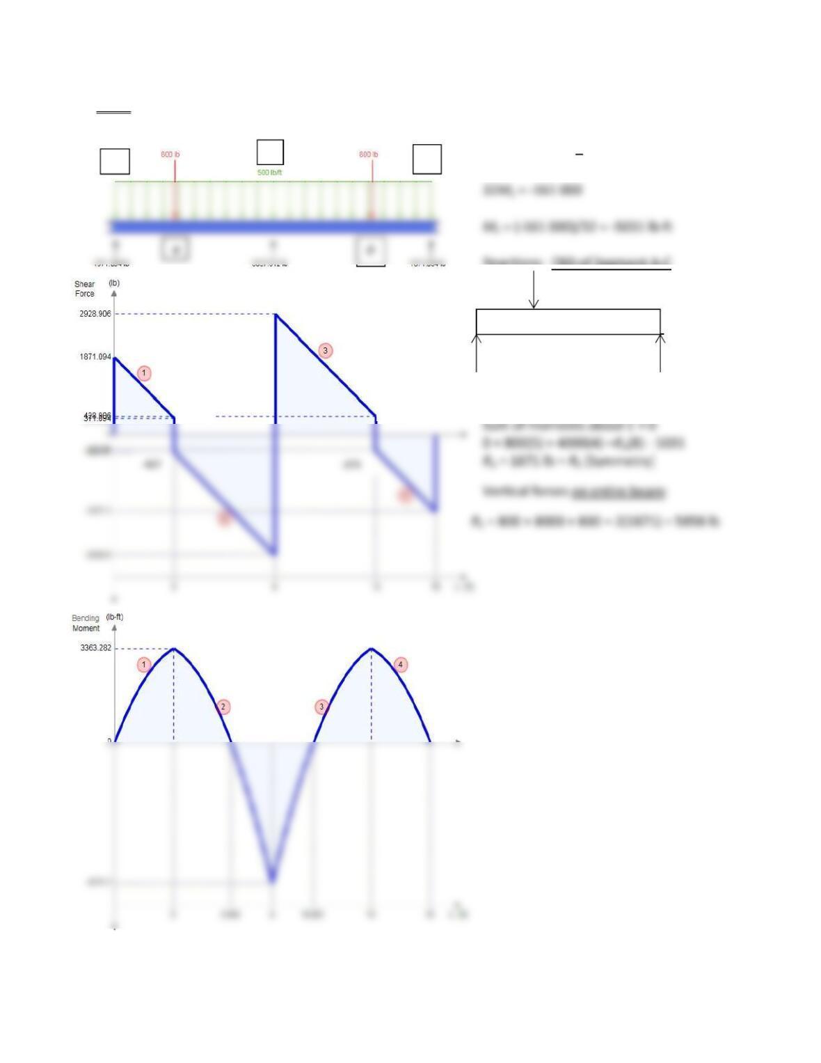
5-125 Use Equation 5-9 with MA = ME = 0. Subscripts adjusted to match those in Figure 5-125.
0 + 2MC(8+8) + 0 = -800(3/8)(82-32)
-800(3/8)( 82-32) 500(83)/4 – 500(83)/4
Reactions: FBD of Segment A-C
800 lb
3 ft 5 ft
MC =
-5031 CW
RA RC
–
427
A
C
E
500 lb/ft
427
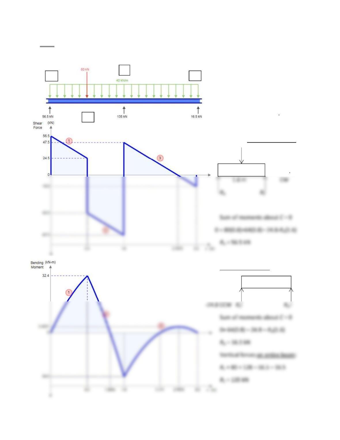
5-126 Use Equation 5-9 with MA = MD = 0. Subscripts adjusted to match those in Figure 5-126.
0 + 2MC(1.62 – 0.82)/1.6
= -80(0.8)(1.62-0.82)/1.6 -40(1.63)/4
– -40(1.63)/4
MC = -158.72/6.4 = -24.8 kN m
Reactions: FBD of segment A-C
0.8 m 80 kN
MC =
-24.8 kN m
FBD of Segment C-D
MC = 1.6 m
A
B
C
D
40 kN/m
40 kN/m
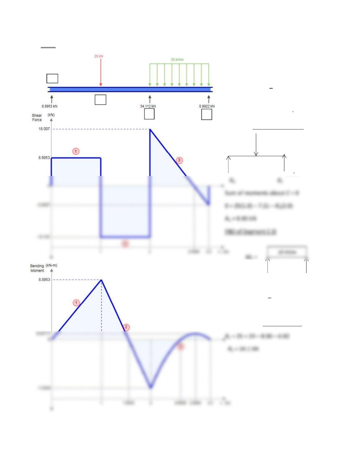
5-127 Use Equation 5-9 with MA = MD = 0. Subscripts adjusted to match those in Figure 5-127.
0 + 2MC(3.2) + 0 =
25(1.0/2.0)(2.02 1.02)
-20(1.23)/4 = -46.14
MC = -46.14/6.4 = -7.21 kN
Reactions: FBD of Segment A-C
25 kN
1.0 m 1.0 m
MC =
–7.21
kNm
-7.21 CCW 1.2 m
RC RD
Sum of moments about C = 0
0 = 24(0.6) -7.21 RD(1.2)
RD = 6.00 kN
Vertical forces on entire beam
A
B
C
D
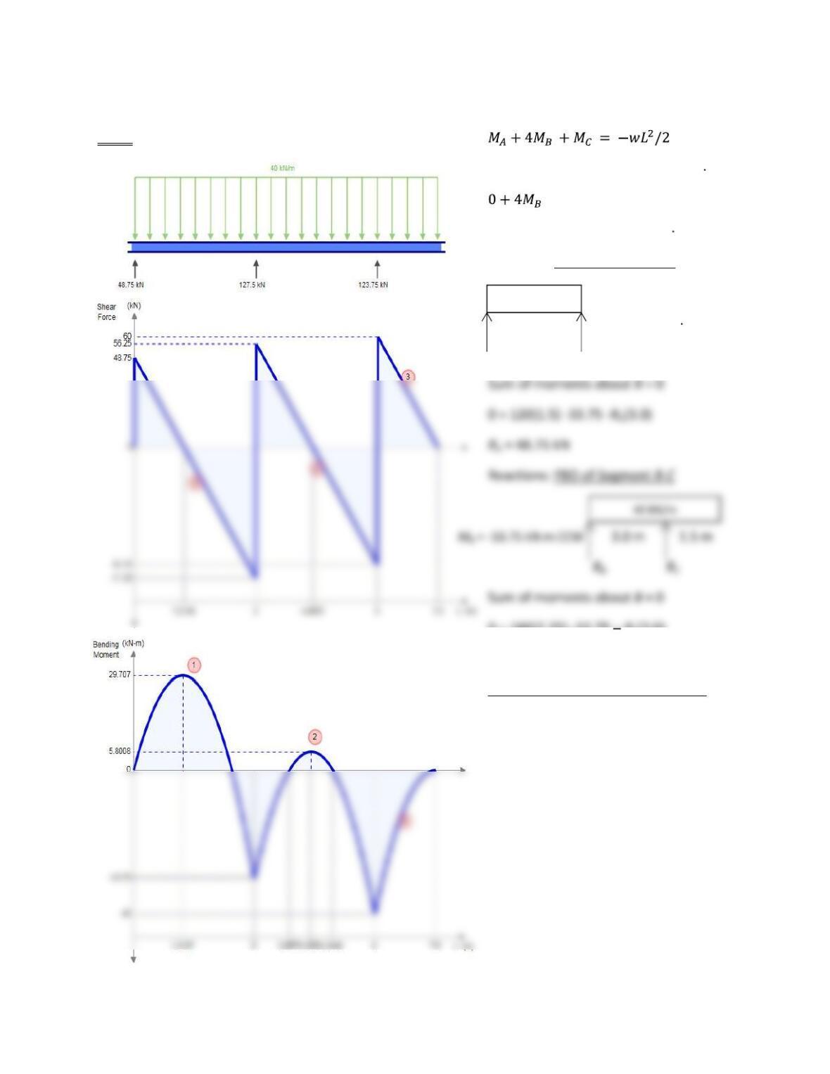
5-128 Use equation 5-6 with MA = 0.
MC = (40 kN/m)(1.5 m)(1.5 m/2) = -45 kN m
-45 = -40(3)2/2 = -180
MB = (-180 + 45)/4 = -33.75 kN m
Reactions: FBD of Segment A-B
3.0 m MB = -33 .75 kN m CW
RA RB
0 = 180(2.25) -33.75 RC(3.0)
RC= 123.75 kN
Using vertical forces on entire beam:
RB = 300 – 48.75 – 123.75 = 127.5 kN
40 kN/m
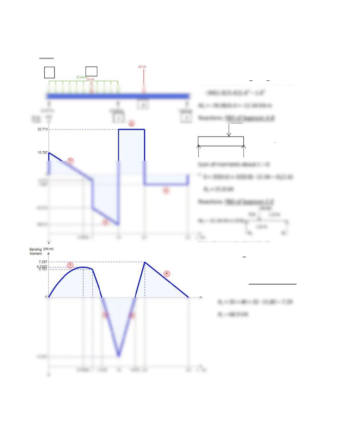
5-129 Use Equation 5-9 with MA = ME = 0. Subscripts adjusted to match those in Figure 5-129.
0 + 2MC(3.2) + 0 =
[-20(1.0)/1.6](1.62 1.02) 20(1.63)/4
20 kN
1.0 m 0.6 m
MC = -12.34 kN m CW
RA RC
Sum of moments about C = 0
0 = 40(0.6) -12.34 RE(1.6)
RE = 7.29 kN
Using vertical forces on the entire beam
to find RC:
A
B
20 kN/m
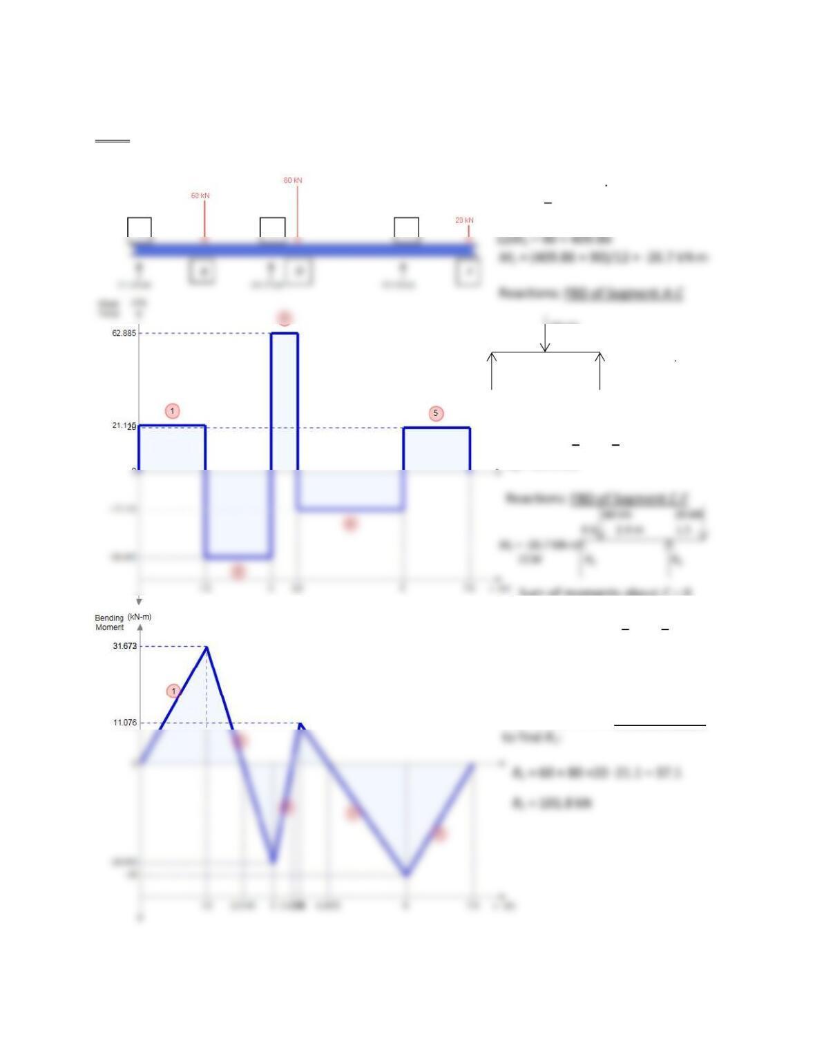
5-130 Use Equation 5-7 with MA = 0. Note: Subscripts in Equation 5-
7 are adjusted to match to notation
I in Figure P5-130.
ME = 20(1.5) = -30 kN m
0 + 2MC(6) 30(3) = -[60(1.5)/3](32-1.52)
– [80(2.4)/3](32-2.42)
60 kN
1.5 1.5
MC = -26.7 kN m CW
RA RC
Sum of the moments about C = 0
0 = 60(1.5) 26.7 RA(3)
RA = 21.1 kN
Sum of moments about C = 0
0 = 80(0.6) +20(4.5) 26.7 RE(3.0)
RE = 37.1 kN
Use vertical forces on entire beam
A
C
E