298
Solution
a. The characteristic length of the junction is
3
4
body 3
c2
surface
ʌ1 0.001
4ʌ
Vr
Lr
Ar
The Biot number of the junction is
Thus, the junction can be treated as a lump-temperature system, and its temperature can be considered uniform
within the body.
b. Applying the law of conservation of energy to the junction gives
hi ho
dU qq
dt
where
and the thermal resistance due to convection is
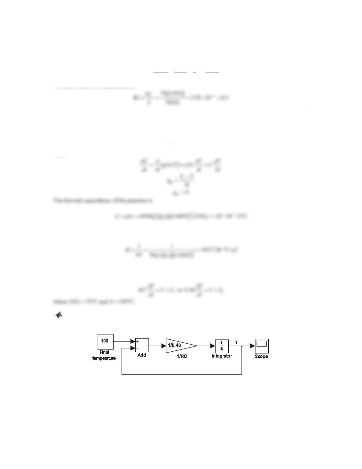
Thus, the dynamic model of the junction’s temperature is
c. The Simulink block diagram is shown in Plot (a). Based on the response shown in Plot (b), we can estimate
the time it will take the thermocouple to read 99% of the water’s temperature.
Figure PS7-3 No3a
299
40
50
60
70
80
90
100
q
C)
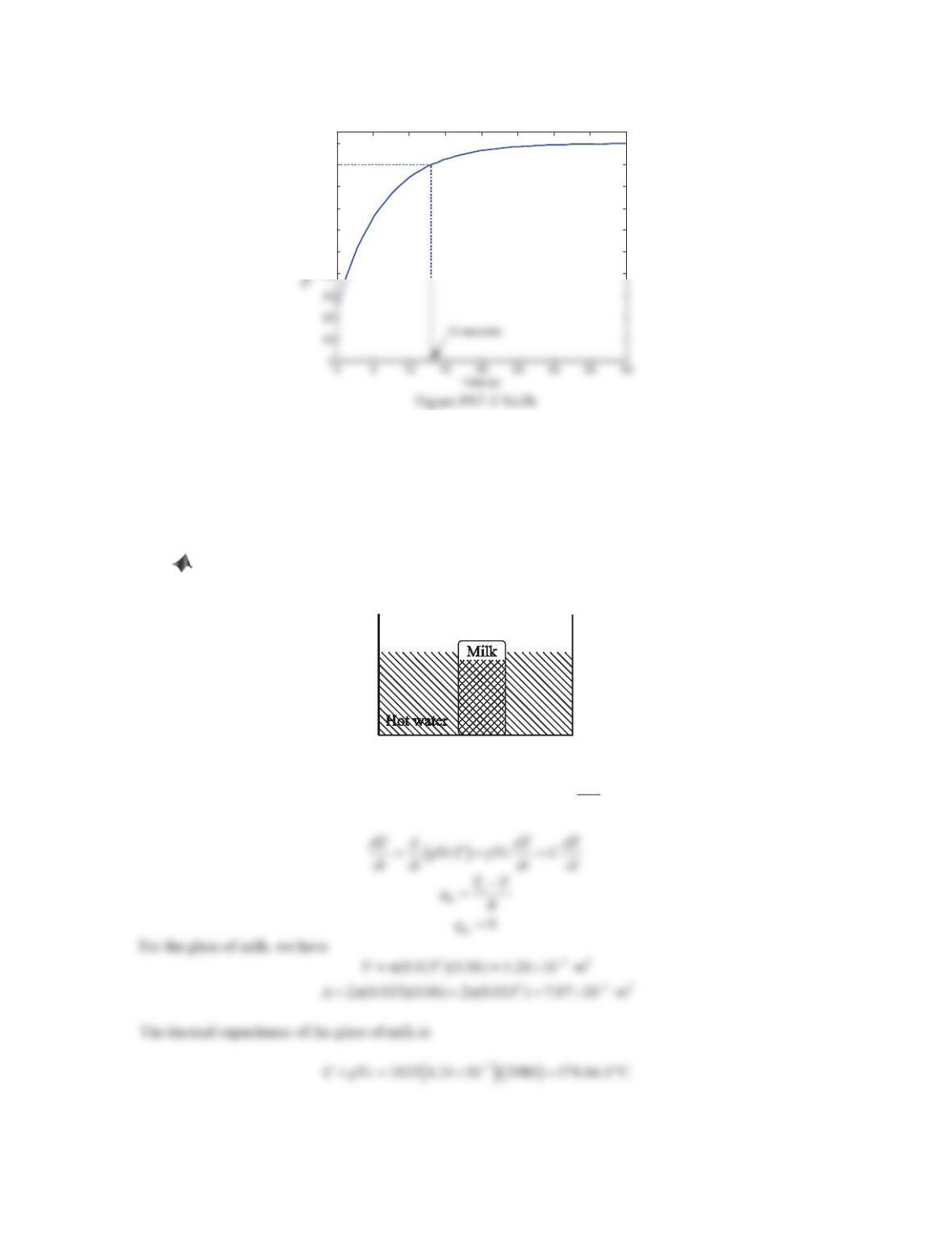
4. Figure 7.33 shows a thin-walled glass of milk, which is taken out of the refrigerator at a uniform temperature of
3°C and is placed in a large pan filled with hot water at 60°C. Assume that the assumption of the lumped system
analysis is applicable since the milk is stirred constantly, so that its temperature is uniform at all times. The
glass container is cylindrical in shape with a diameter of 3 cm and a height of 6 cm. The estimated parameters
of the milk are: density U=1035kg/m
3, specific heat capacity c= 3980 J/(kg·°C), and thermal conductivity is k
= 0.56 W/(m·°C). The heat transfer coefficient between the water and the glass is h= 250 W/(m2·°C).
a. Derive the differential equation relating the milk’s temperature T(t) and the water temperature.
b. Using the differential equation obtained in Part (a), construct a Simulink block diagram. How long
will it take for the milk to warm up from 3 °C to 58 °C?
Figure 7.33 Problem 4.
Solution
a. Applying the law of conservation of energy to the glass of milk gives
hi ho
dU qq
dt
, where
250 7.07 10
u
Thus, the dynamic model of the chicken’s temperature is
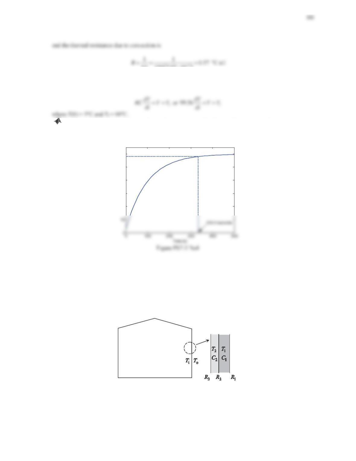
b. The Simulink block diagram is similar to the one shown in Problem 3. The response of the temperature of
the glass of milk is shown below. As seen from the plot, it takes 333.5 seconds for the milk to warm up from 3
°C to 58 °C .
20
30
40
50
60
Temperature (
q
C)
5. As shown in Figure 7.34, the wall of a room consists of two layers, for which the thermal capacitances are C1
and C2. Assume that the temperatures in both layers are uniform and they are T1and T2, respectively. The
temperatures inside and outside the room are Tiand To, respectively. Both layers exchange heat by convection
with air and the thermal resistances are R1and R3, respectively. The thermal resistance of the interface between
the layers is R2.
a. Derive the differential equations for this system.
b. Using the differential equations obtained in Part (a), determine the state-space form of the system. Assume
the temperatures T1and T2are the outputs.
Figure 7.34 Problem 5.
Solution
a. Assume that the temperature inside the room is lower than the one outside. Applying the law of conservation of
energy to the outer layer, we have
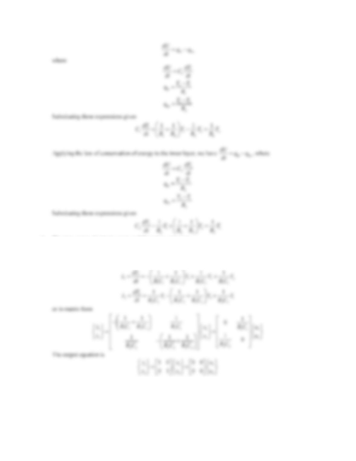
301
b. The state vector, the input vector, and the output vector are
i
11 1
o
22 2
,,
T
xT T
T
xT T
½
½½ ½
®¾®¾ ®¾ ®¾
¯¿¯¿ ¯¿
¯¿
xuy
The state-variable equations are
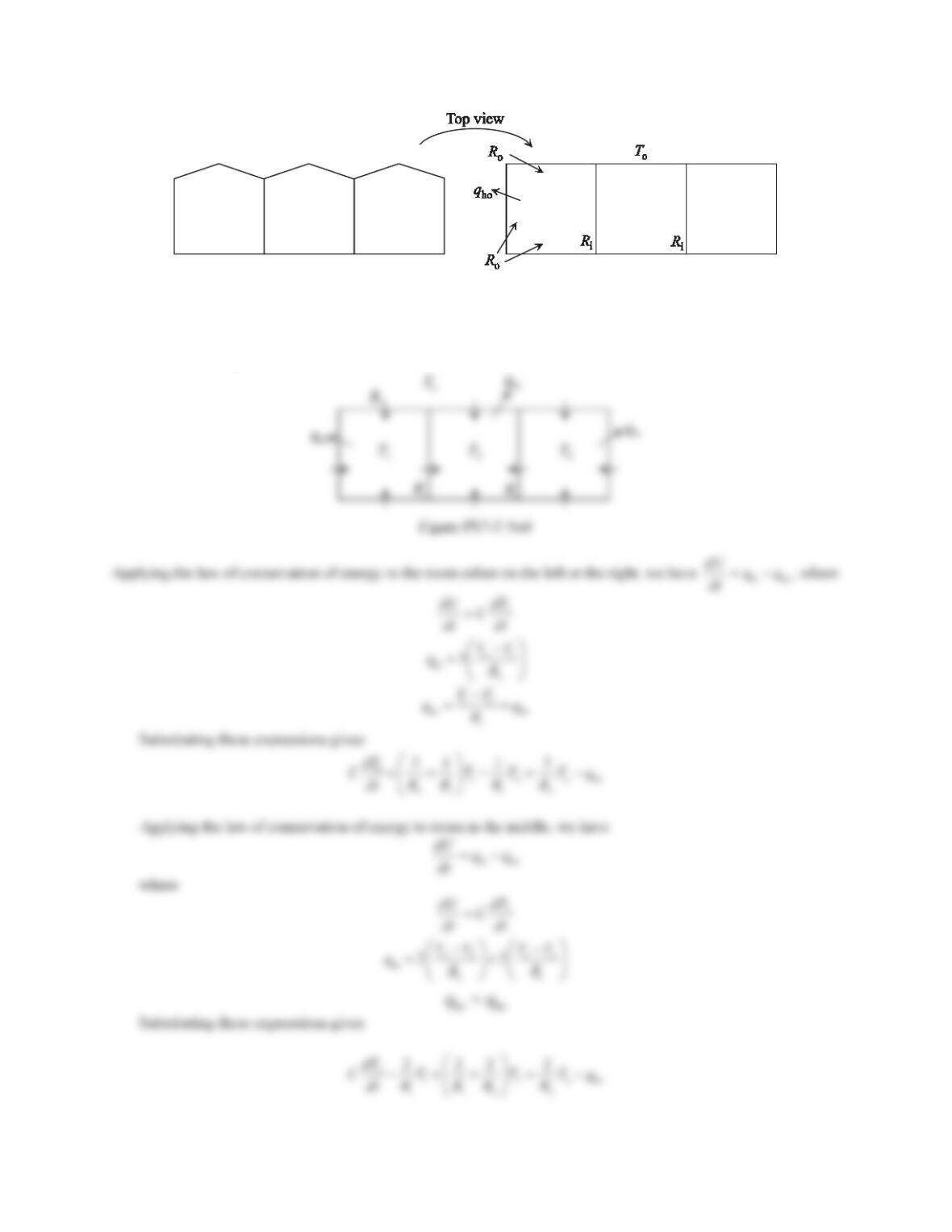
6. For a three-room house shown in Figure 7.35, all rooms are perfect square and have the same dimensions. An
air conditioner produces an equal amount of heat flow qho out of each room. The temperature outside the house
is To. Assume that there is no heat flow through the floors or ceilings. The thermal resistances through the inner
walls and the outer walls are Riand Ro, respectively. The thermal capacitance of each room is C. Derive the
differential equations for this system.
302
Figure 7.35 Problem 6.
Solution
Due to symmetry, the temperatures in the rooms on the left and on the right are the same, and they are assumed to be
T1. Assume that the temperature in the room in the middle is T2. It is obvious that T1>T2since there are heat flow
into the room through the walls on the three sides instead of on the two sides.
303
Problem Set 7.4
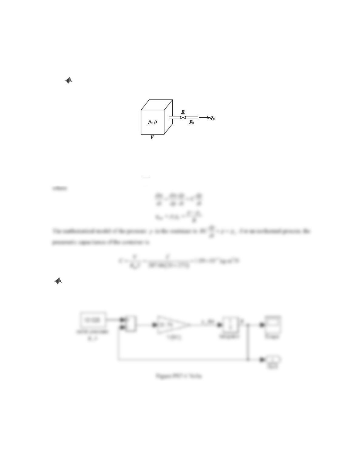
1. Dry air at a constant temperature of 20°C passes through a valve out of a rigid cubic container of 1 m on each
side (see Figure 7.46). The pressure poat the outlet of the valve is constant, and it is less than p. The valve
resistance is approximately linear, and R= 1000 Pa·s/kg. Assume the process is isothermal.
a. Develop a mathematical model of the pressure pin the container.
b. Construct a Simulink block diagram to find the output p(t) of the pneumatic system if the pressure
inside the container initially is 2 atm and the pressure at the outlet is 1 atm.
Figure 7.46 Problem 1.
Solution
a. Applying the law of conservation of mass gives
mi mo mo mo
0
dm qq q q
dt
b. The Simulink block diagram is constructed based on the above differential equation, where
1000R
Pas/kg , o1 atm 101.325p kPa, and
5
1.09 10C
u
kgm2/N. Double-click the Integrator block to set
the initial pressure to be 202650 Pa (2 atm). The response of the system is shown in the Plot (b).
00.2 0.4 0.6 0.8 1
1
1.2
1.8
Time (s )
Figure PS7-4 No1b
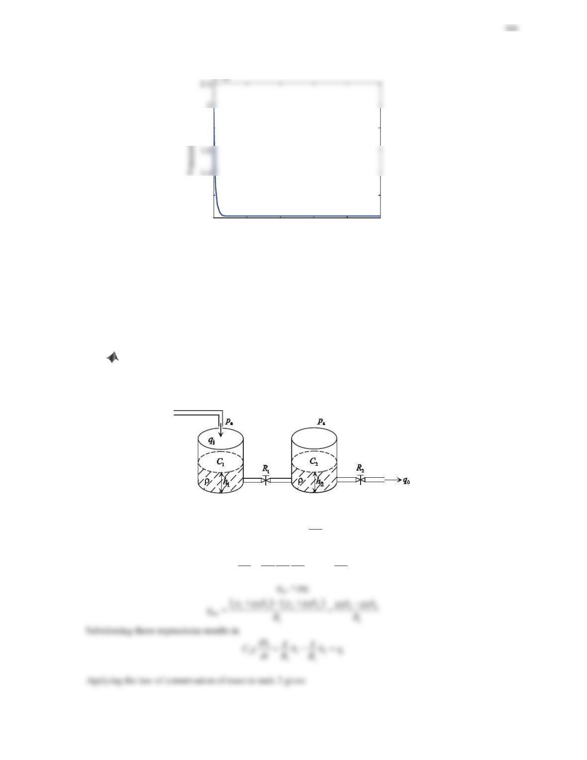
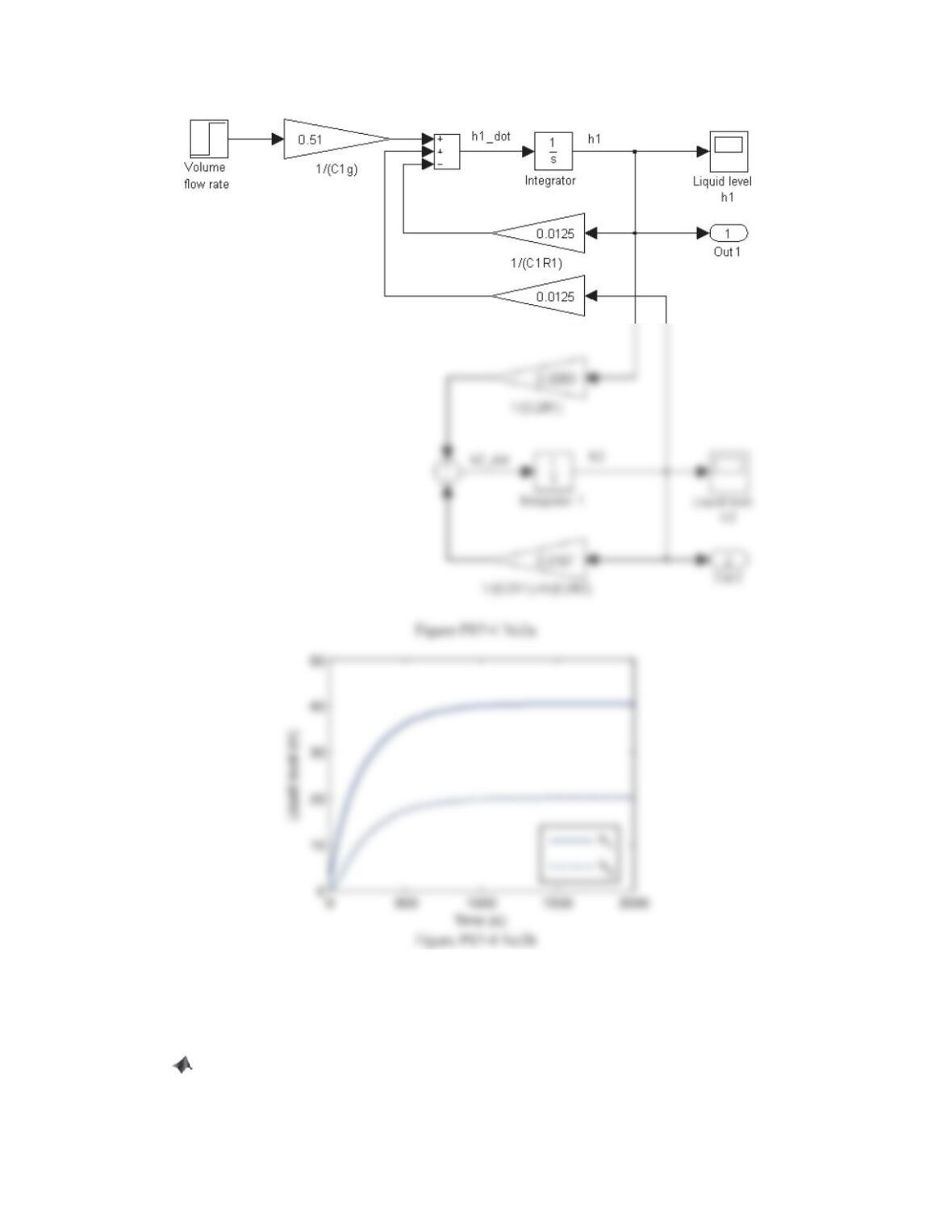
2. Figure 7.47 shows a liquid-level system in which two tanks have hydraulic capacitances C1and C2,
respectively. The volume flow rate into tank 1 is qi. The liquid flows from tank 1 to tank 2 through a valve of
linear resistance R1and leaves tank 2 through a valve of linear resistance R2 7KH GHQVLW\ ȡ RI WKH OLTXLG LV
constant.
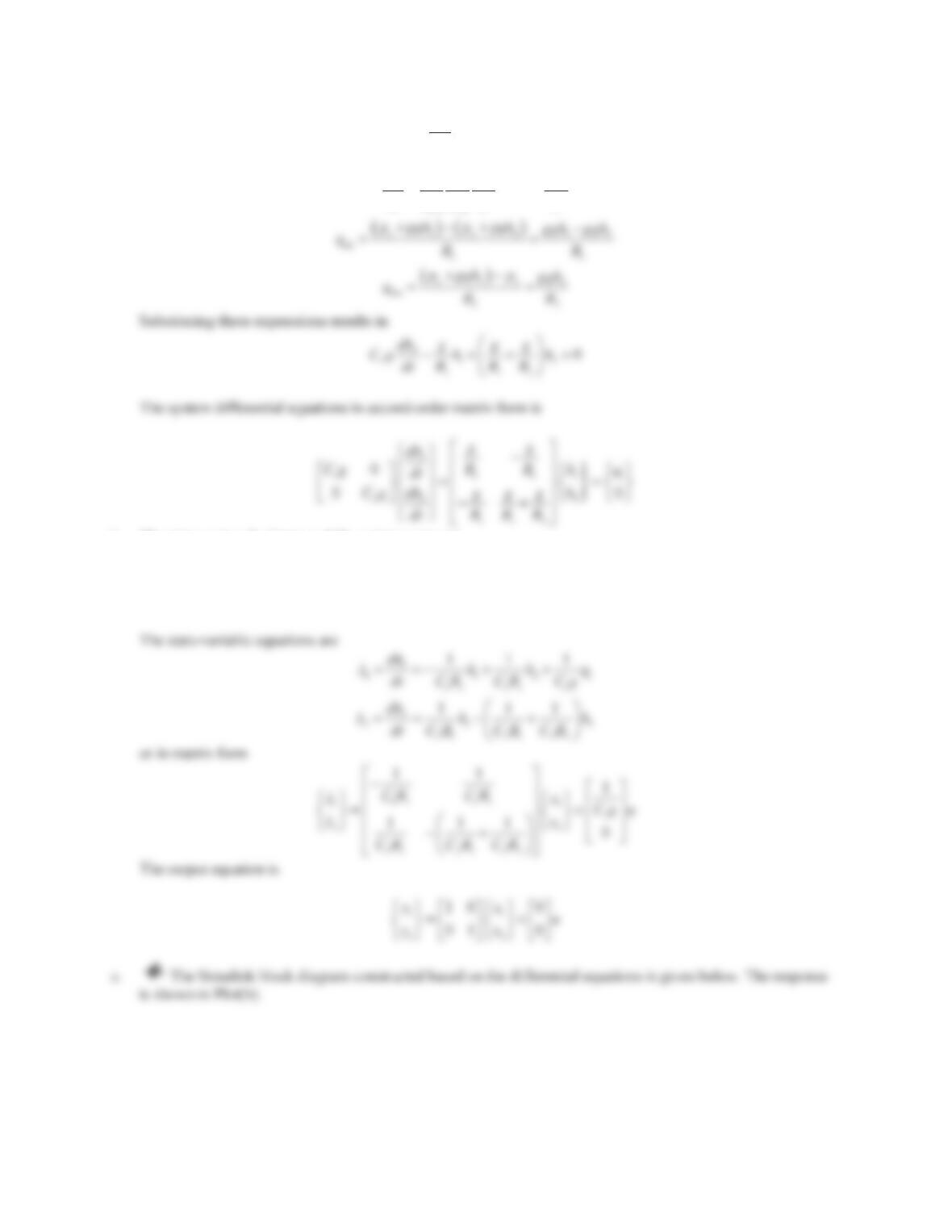
a. Derive the differential equations in terms of the liquid heights h1and h2. Write the equations in second–
order matrix form.
b. Assume the volume flow rate qiis the input and the liquid heights h1and h2are the outputs. Determine the
state-space form of the system.
c. Construct a Simulink block diagram to find the outputs h1(t) and h2(t) of the liquid-level system.
$VVXPHȡ NJP3,g= 9.81 m/s2,C1= 0.2 kg·m2/N, C2= 0.3 kg·m2/N, R1=R2= 400 N·s/(kg·m2),
and initial liquid heights h1(0) = 1 m and h2(0) = 0 m. The volume flow rate qiis a step function with a
magnitude of 0 before t= 0 s and a magnitude of 0.5 m3/s after t= 0 s.
Figure 7.47 Problem 2.
Solution
a. Applying the law of conservation of mass to tank 1 gives
mi mo
dm qq
dt
, where
11 1
1
11
ȡ
dp dh dh
dm dm Cg
dt dp dh dt dt
305
mi mo
dm qq
dt
where
22 2
2
22
ȡ
dp dh dh
dm dm Cg
dt dp dh dt dt
b. The state vector, the input, and the output vector are
11 1
i
22 2
,,
xh h
uq
xh h
½½ ½
®¾®¾ ®¾
¯¿¯¿ ¯¿
xy
306
3. A chicken is taken out of the oven at a uniform temperature of 150°C and is left out in the open air at the room
temperature of 25°C. Assume that the chicken can be approximated as a lumped model. The estimated
parameters are: mass m= 2 kg, heat transfer surface area A= 0.32m2, specific heat capacity c= 3220 J/(kg·°C),
and heat transfer coefficient h= 15 W/(m2·°C).
a. Derive the differential equation relating the chicken’s temperature T(t) and the room temperature.
b. Using the differential equation obtained in Part (a), construct a Simulink block diagram and find the
temperature of the chicken.
307
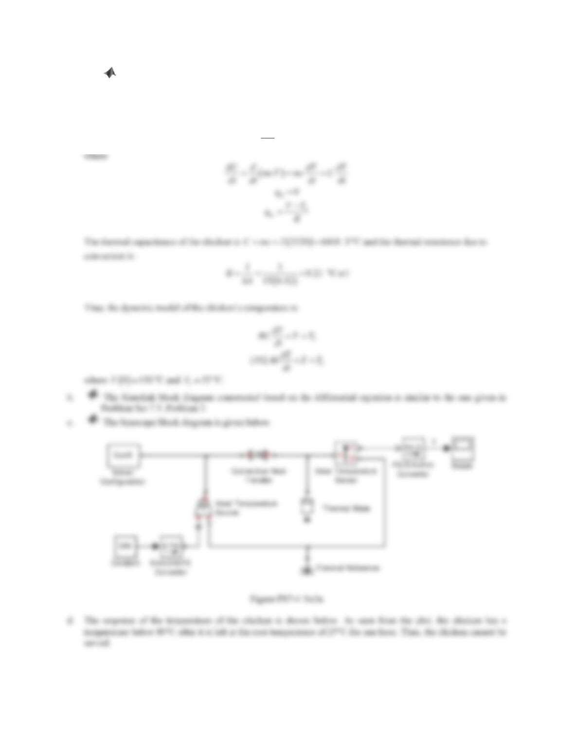
c. Build a Simscape model of the system and find the temperature of the chicken.
d. Assume that the chicken can be served only if its temperature is above 80°C. Based on the simulation
results obtained in Parts (b) and (c), can the chicken be left at the room temperature of 25°C for one hour?
Solution
a. Applying the law of conservation of energy to the chicken gives
hi ho
dU qq
dt
308
01000 2000 3000 4000 5000 6000 7000
280
300
320
340
360
380
400
420
440
Time (s)
Temperature (K)
3600 seconds
306 K
33 qC
Figure PS7-4 No3b
Review Problems
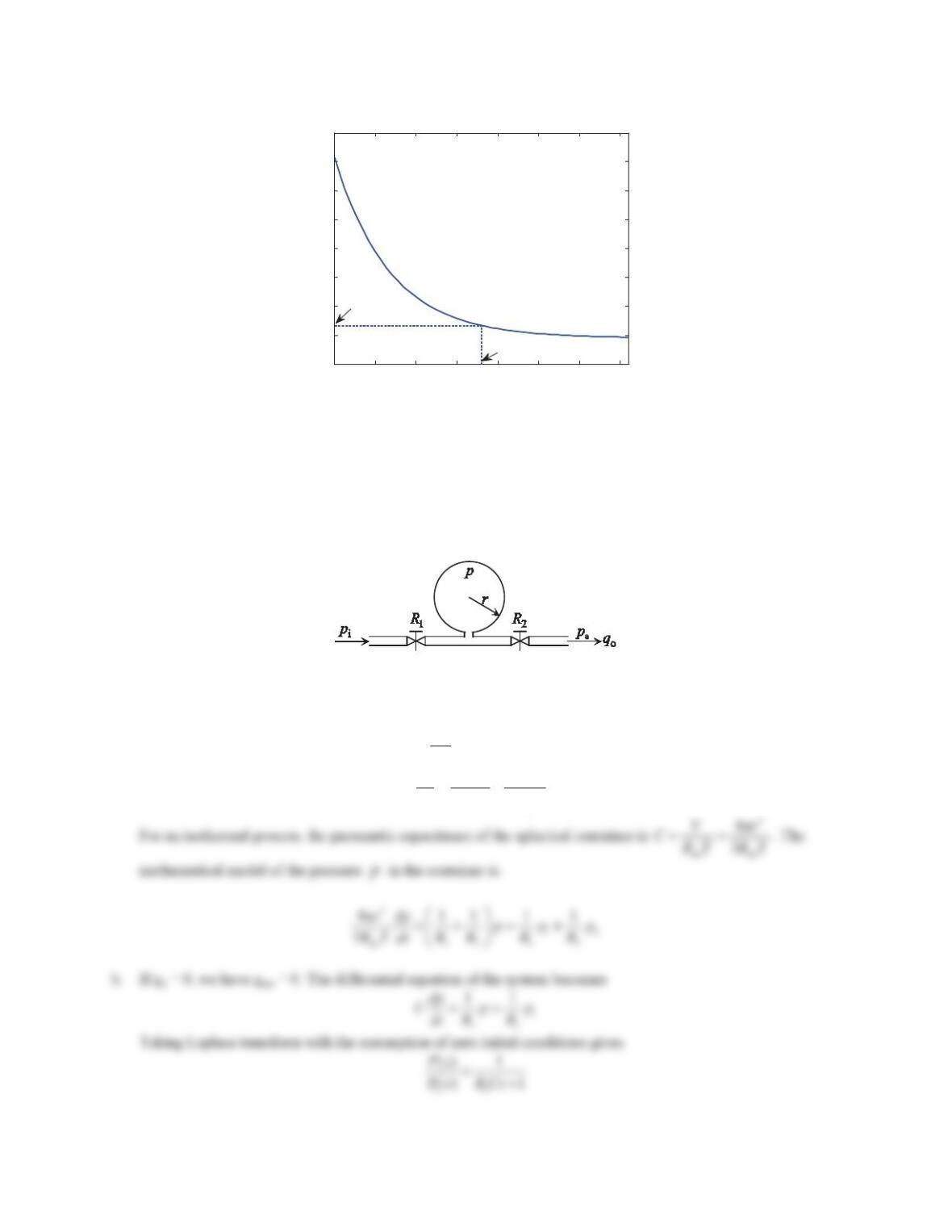
1. Dry air at a constant temperature of Tpasses through a valve into a rigid spherical container (see Figure 7.48).
The pressure at the inlet is piand the one at the outlet is pa. The linear resistances of the two valves at the inlet
and the outlet are R1and R2, respectively. Assume that the process is isothermal.
a. Develop a mathematical model of the pressure pin the container.
b. Denote the volume flow rate at the outlet as qo. Determine the transfer function relating piand pfor this
pneumatic system if qo= 0.
Figure 7.48 Problem 1.
Solution
a. Applying the law of conservation of mass gives
mi mo
dm qq
dt
a
i
12
pp
pp
dp
Cdt R R
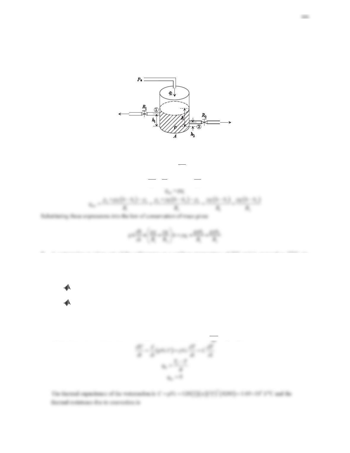
2. A single-tank liquid-level system is shown in Figure 7.49, where water flows into the tank at a volume flow rate
qiand out of the tank through two valves at points 1 and 2. The linear resistances of the two valves are R1and
R2, respectively. Assuming h>h1, derive the differential equation relating the liquid height hand the volume
flow rate qiat the inlet. The cross-sectional area of the tank Ais constant. The dHQVLW\ȡRIWKHOLTXLGLVFRQVWDQW
Figure 7.49 Problem 2.
Solution
Applying the law of conservation of mass to the tank gives
mi mo
dm qq
dt
, where
ȡȡ
dm d dh
Ah A
dt dt dt
3. A watermelon is taken out of the refrigerator at a uniform temperature of 5°C and is exposed to 27°C air.
Assume that the watermelon can be approximated as a sphere and the temperature of the watermelon is uniform.
The esWLPDWHGSDUDPHWHUVDUHGHQVLW\RIZDWHUPHORQȡ NJP3, diameter of the watermelon D= 40 cm,
specific heat capacity c= 4200 J/(kg·°C), and heat transfer coefficient h= 15 W/(m2·°C).
a. Derive the differential equation relating the watermelon’s temperature T(t) and the air temperature.
b. Using the differential equation obtained in Part (a), construct a Simulink block diagram and find the
temperature of the watermelon.
c. Build a Simscape model of the system.
d. Based on the simulation results obtained in Parts (b) and (c), how long will it take before the watermelon is
warmed up to 20°C?
Solution
a. Applying the law of conservation of energy to the watermelon gives
hi ho
dU qq
, where
310
Thus, the dynamic model of the watermelon’s temperature is
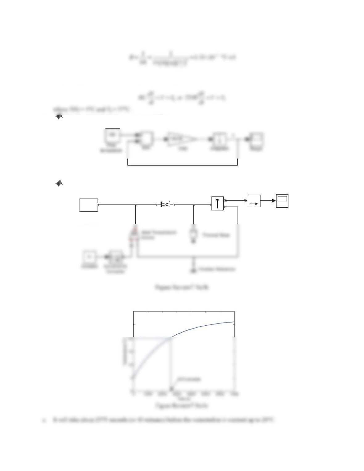
a. The Simulink block diagram is given below.
Figure Review7 No3a
b. The Simscape block diagram is given below.
T
f(x)=0
Solver
Configuration
Scope
SPS
PS-Simulink
Converter
T
B
A
Ideal Temperature
Sensor
BA
Convective Heat
Transfer
Running either of the block diagrams yields the same response curve as shown in the figure above.
25
30