285
Problem Set 7.1
1. A car has an internal volume of 2.8 m3. If the sun heats the car from a temperature of 20°C to a temperature of
40°C, what will the pressure inside the car be? Assume the pressure is initially 1 atm.
Solution
This is a constant-volume process, where
1
20 C 293T
D
K,
2
40 C 313T
D
K, and 11 atm 101325p Pa. We
2. Find the pneumatic capacitance of dry air in a rigid container with volume 15 ft3for an isothermal process.
Assume the air is initially at ambient temperature of 68°F.
Solution
The capacitance of a container is
g
V
CnR T
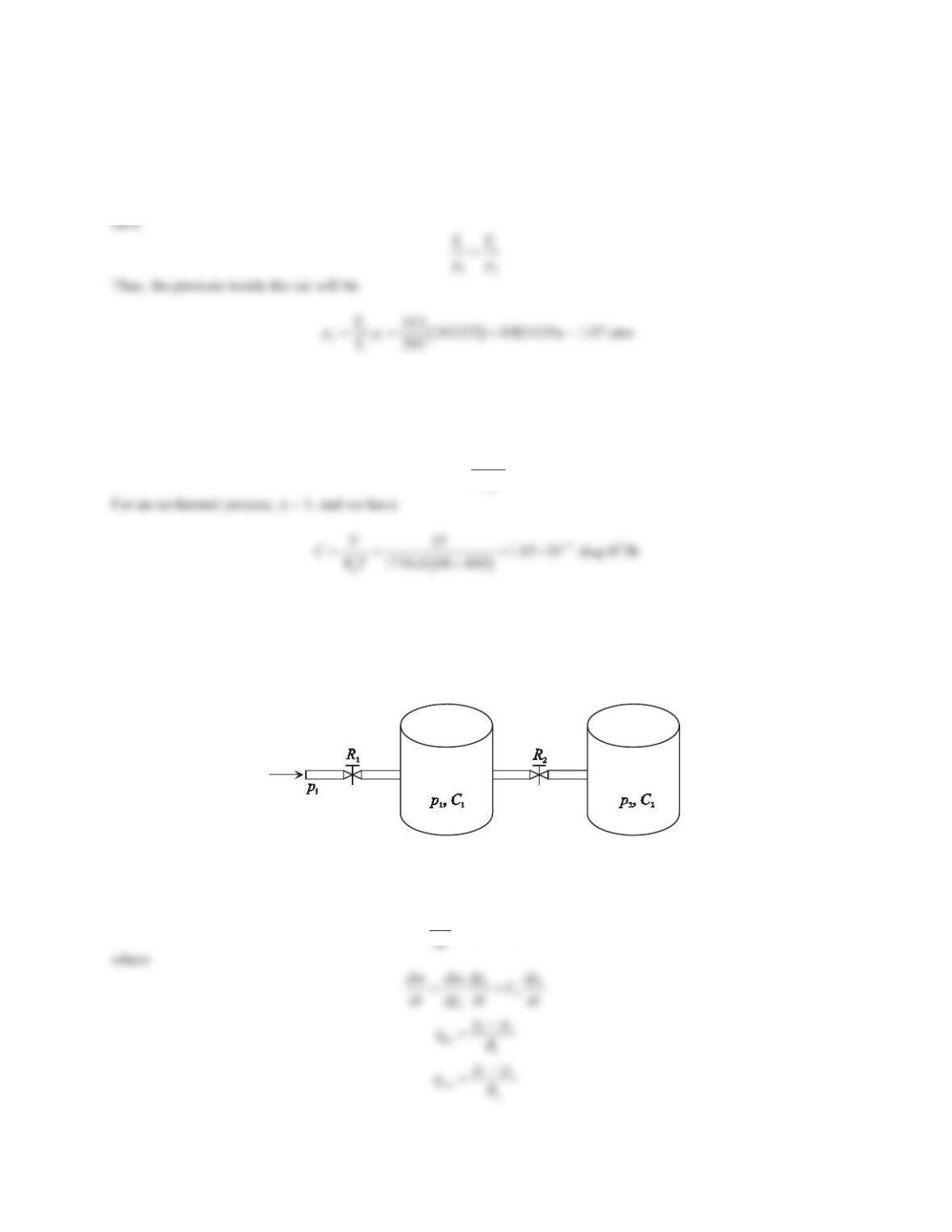
3. Figure 7.3 shows a pneumatic system, where the pneumatic capacitances of the two rigid containers are C1and
C2, respectively. Dry air at a constant temperature passes through a valve of linear resistance R1into container
1. The pressure piat the inlet of the valve is constant, and it is greater than p1. The air flows from container 1 to
container 2 through a valve of linear resistance R2. Derive the differential equations in terms of the pressures p1
and p2. Write the equations in second-order matrix form.
Figure 7.3 Problem 3.
Solution
Applying the law of conservation of mass to container 1 gives
mi mo
dm qq
286
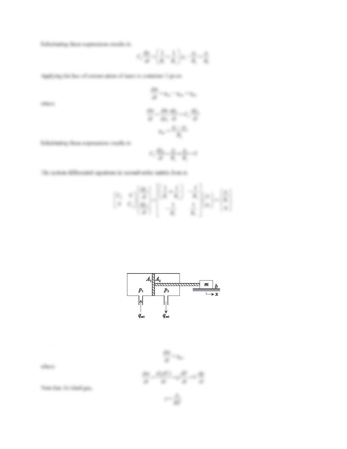
4. Figure 7.4 shows a pneumatic piston, which can exert a force in one direction and serve as a translational
actuator. The displacement of the piston is x,mis the total mass of the piston and the load, and bis the damping
coefficient. Use subscript ito denote the chamber index and i= 1, 2. As shown in Figure 7.4, piis the absolute
pressure in the chamber, qmiis the mass flow rate at the port, and Aiis the effective area of the piston. The two
chambers have the same initial volume of V0. Assuming ideal gas and isothermal process, Ris the specific gas
constant and Tis the absolute gas temperature. Derive the dynamic equations of the pressure change in the
pneumatic chambers and the equation of motion of the mass block.
Figure 7.4 Problem 4.
Solution
Applying the law of conservation of mass to chamber 1 gives
287
Problem Set 7.2
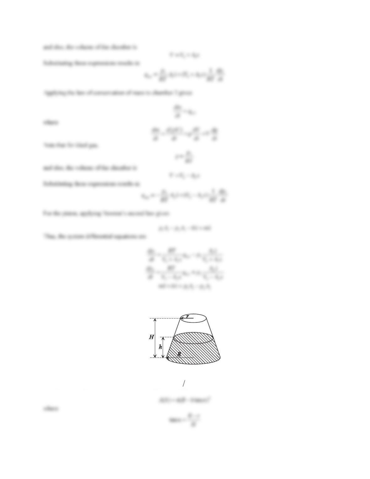
1. Derive the capacitance of the tank shown in Figure 7.13. There is an opening at the top of the tank at height H.
Figure 7.13 Problem 1.
Solution
The hydraulic capacitance can be derived using ()CAhg . The cross-sectional area is
288
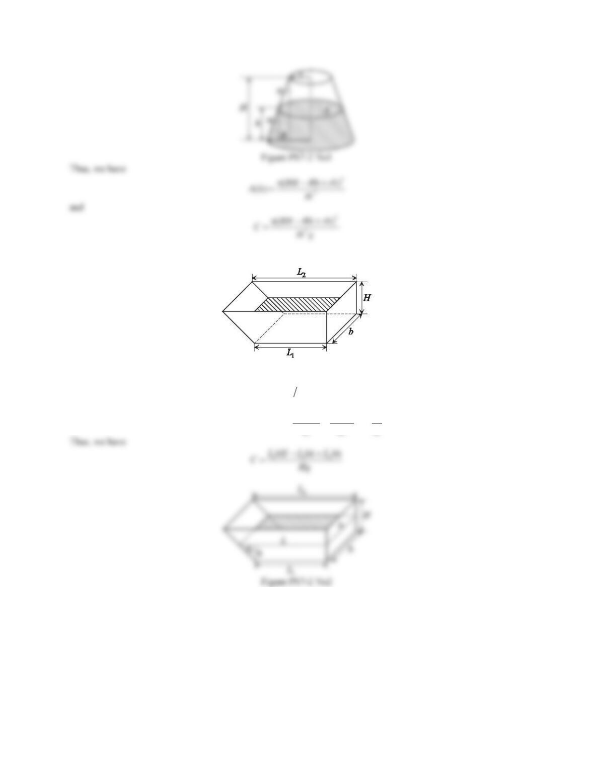
2. Derive the capacitance of the tank shown in Figure 7.14.
Figure 7.14 Problem 2.
Solution
The hydraulic capacitance can be derived using ()CAhg , where
()Ah bL
. The length Lis
21
11 12
tan ĮLL Hh h
LLh Lh L L
HHH
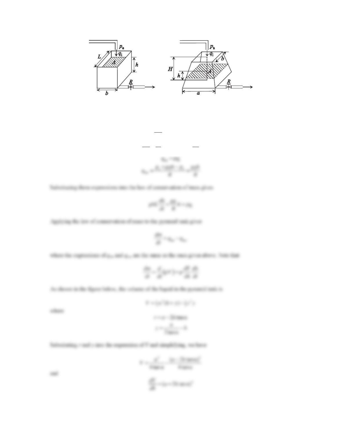
3. Consider the rectangular tank in Figure 7.15a and the pyramid tank in Figure 7.15b. The volume flow rate into
each tank through a pipe is qi. The liquid leaves each tank through a valve of linear resistance R7KHGHQVLW\ȡ
of the liquid is constant.
a. Derive the dynamic model of the liquid height hfor each tank.
b. For each tank, write the differential equation in terms of hydraulic capacitance and hydraulic resistance.
Compare the models for the two single-tank systems.
289
Figure 7.15 Problem 3.
Solution
a. Applying the law of conservation of mass to the rectangular tank gives
mi mo
dm qq
dt
where
ȡȡ
dm d dh
bLh bL
dt dt dt
290
b. The hydraulic capacitance for the rectangular tank is
Ah bL
Cgg
Thus, the differential equation can be written as
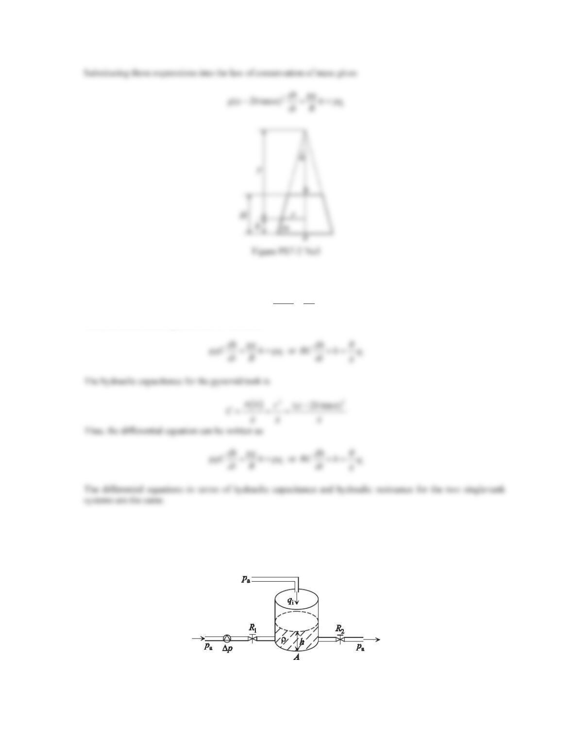
4. Consider the single-tank liquid-level system shown in Figure 7.16, where the volume flow rate into the tank
through a pipe is qi. The pump is connected to the bottom of the tank through a valve of linear resistance R1.
7KHSUHVVXUHRIWKHIOXLGLQFUHDVHVE\ǻpwhen crossing the pump. The liquid leaves the tank through a valve of
linear resistance R2. Derive the differential equation relating the liquid height hand the volume flow rate qiat
the inlet. The tank’s cross-sectional area ALVFRQVWDQW7KHGHQVLW\ȡRIWKHOLTuid is constant.
Figure 7.16 Problem 4.
291
Solution
Applying the law of conservation of mass to the tank gives
mi mo
dm qq
dt
For constant fluid density and constant cross-sectional area, we have
ȡȡ
dm d dh
Ah A
dt dt dt
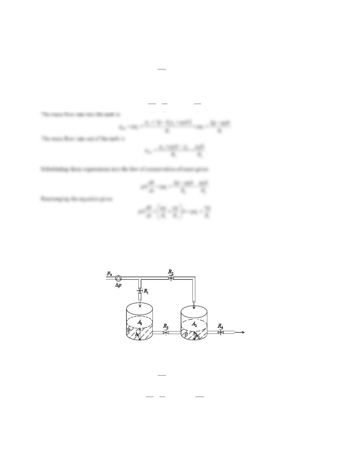
5. Consider the two-tank liquid-level system shown in Figure 7.17. The liquid is pumped into tanks 1 and 2
through valves of linear resistances R1and R2 UHVSHFWLYHO\ 7KH SUHVVXUH RI WKH IOXLG LQFUHDVHV E\ ǻpwhen
crossing the pump. The cross-sectional areas of the two tanks are A1and A2, respectively. The liquid flows from
tank 1 to tank 2 through a valve of linear resistance R3and leaves tank 2 through a valve of linear resistance R4.
7KHGHQVLW\ȡRIWKHOLTXLGLVFRQVWDQW‘HUive the differential equations in terms of the liquid heights h1and h 2.
Write the equations in second-order matrix form.
Figure 7.17 Problem 5.
Solution
Applying the law of conservation of mass to tank 1 gives
mi mo
dm qq
dt
where
1
11 1
ȡȡ
dh
dm d Ah A
dt dt dt
292
mi i
ȡqq
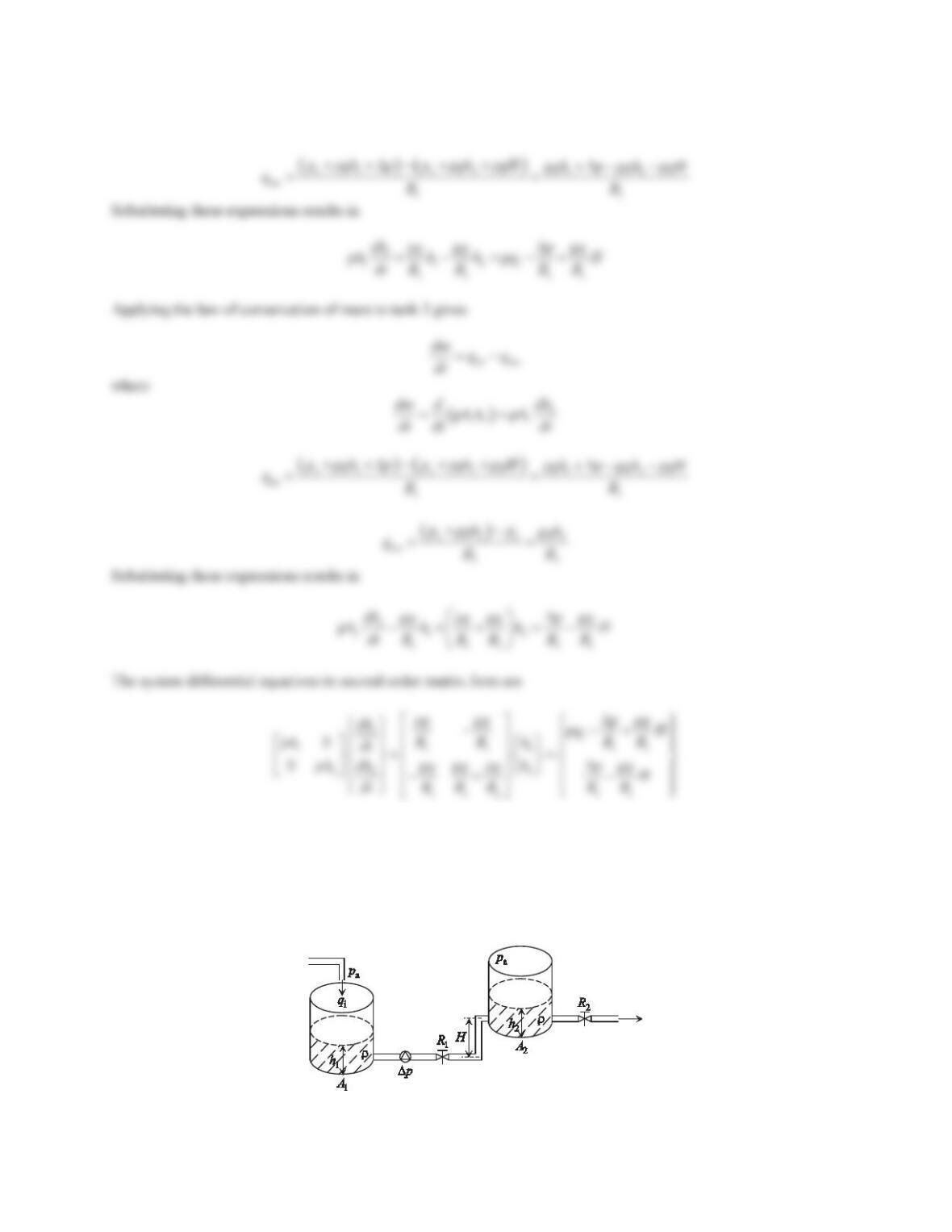
6. Figure 7.18 shows a liquid-level system, in which two tanks have cross-sectional areas A1and A2, respectively.
The volume flow rate into tank 1 is qi. A pump is connected to the bottom of tank 1 and the pressure of the fluid
LQFUHDVHVE\ǻpwhen crossing the pump. Tank 2 is located higher than tank 1 and the vertical distance between
the two tanks is H. The liquid is pumped from tank 1 to tank 2 through a valve of linear resistance R1and leaves
tank 2 through a valve of linear resistance R2 7KH GHQVLW\ ȡ RI WKH OLTXLGLV FRQVWDQW ‘HULYHWKH GLIIHUHQWLDO
equations in terms of the liquid heights h1and h2. Write the equations in second-order matrix form.
Figure 7.18 Problem 6.
293
Solution
Applying the law of conservation of mass to tank 1 gives
mi mo
dm qq
dt
, where
1
11 1
ȡȡ
dh
dm d Ah A
dt dt dt
aa
mi
11
ppp p
qRR
’ ‘
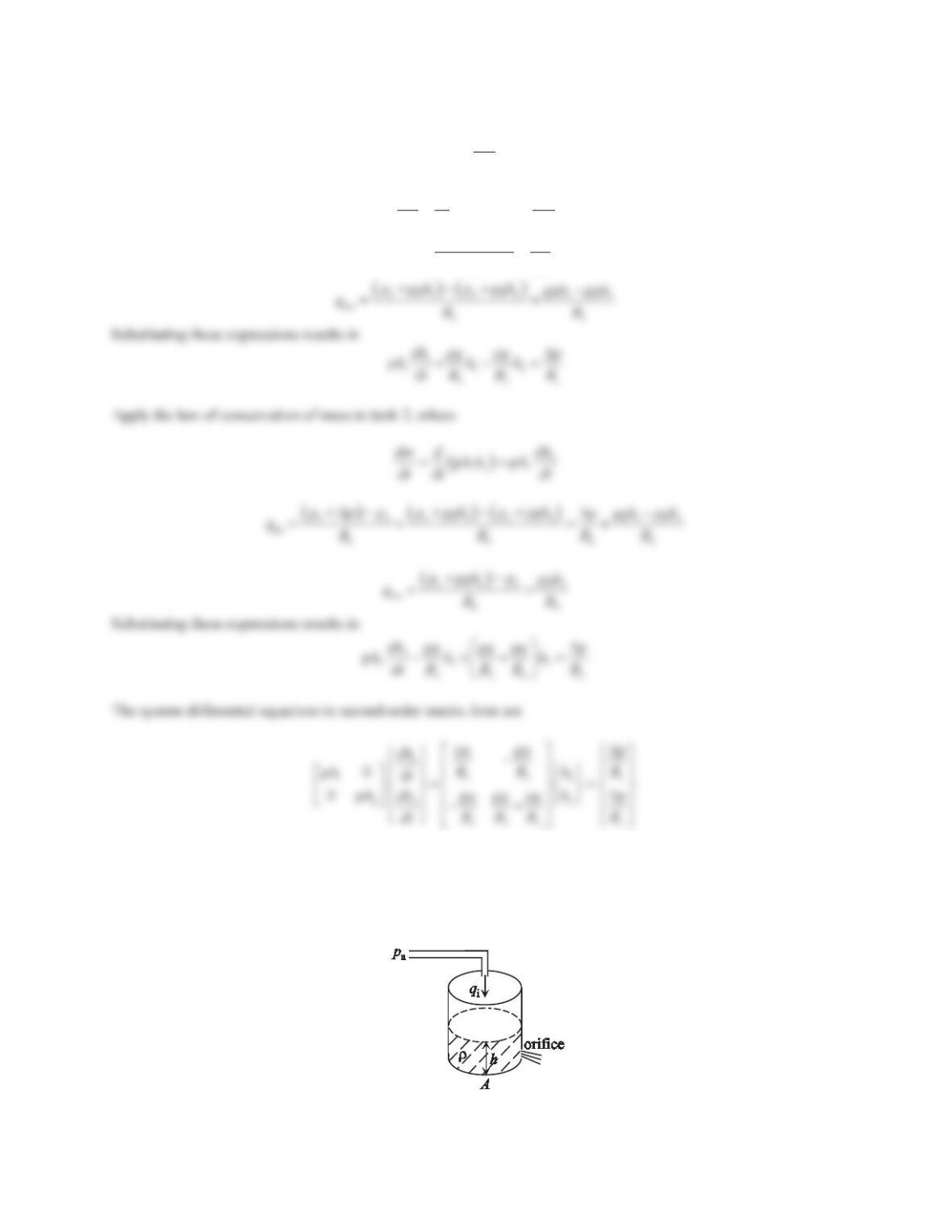
7. Consider the single-tank liquid-level system shown in Figure 7.19, where the volume flow rate into the tank
through a pipe is qi. The liquid leaves the tank through an orifice of area Ao.Denote Cdas the discharge
coefficient, which is the ratio of the actual mass flow rate to the theoretical one, and lies in the range of 0 < Cd<
1 because of friction effects. Derive the differential equation relating the liquid height hand the volume flow
rate qiat the inlet. The tank’s cross-VHFWLRQDODUHDLVFRQVWDQW7KHGHQVLW\ȡRIWKHOLTXLGLVFRQVWDQW.
Figure 7.19 Problem 7.
294
Solution
Applying the law of conservation of mass to the tank gives
mi mo
dm qq
dt
, where
ȡȡ
dm d dh
Ah A
dt dt dt
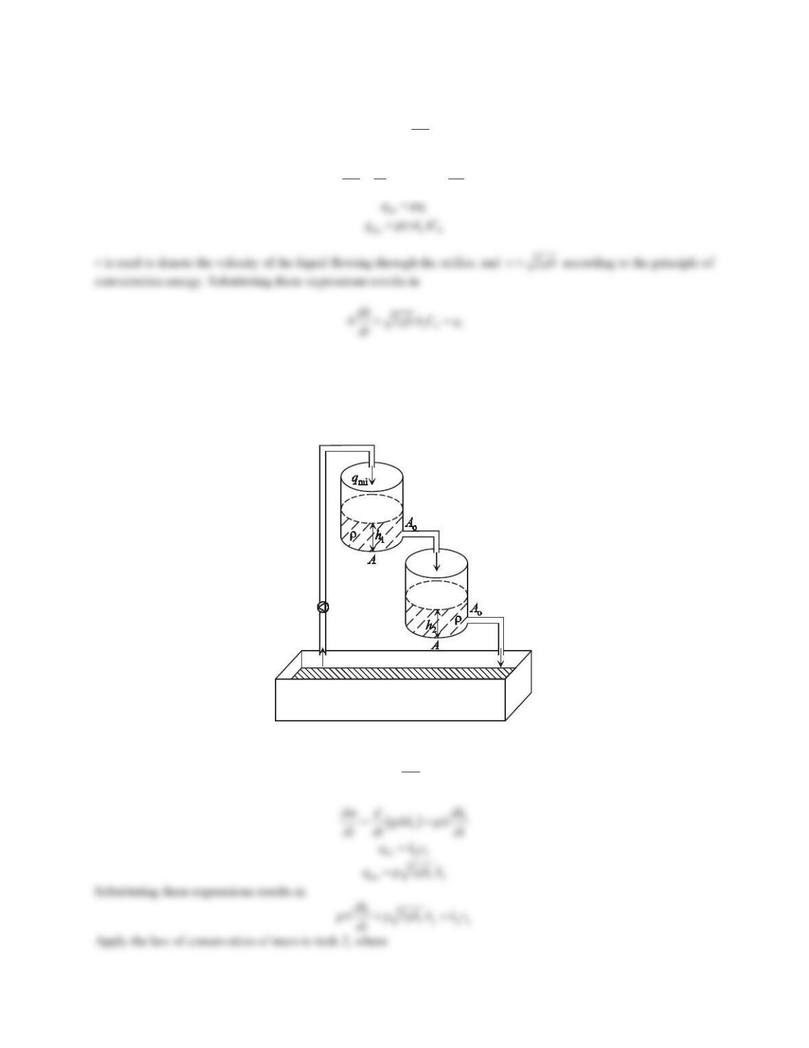
8. Figure 7.20 shows a hydraulic system of two interconnected tanks, which have the same cross-sectional area of
A. A pump is connected to tank 1. Assume that the relationship between the voltage applied to the pump and the
mass flow rate into tank 1 is linear, i.e., qmi =kpva, where kpis called the pump constant and can be obtained by
experimental measurements. Tank 1 is connected to tank 2, which is connected to a reservoir. The liquid leaves
each tank through an outlet of area Aoat the bottom. Derive the differential equations in terms of the liquid
heights h1and h2.
Figure 7.20 Problem 8.
Solution
Applying the law of conservation of mass to tank 1 gives
mi mo
dm qq
dt
,where
295
Problem Set 7.3
1. Consider heat transfer through an insulated frame wall of a house. The thermal conductivity of the wall is 0.055
W/(m·°C). The wall is 0.15 m thick and has an area of 15 m2. The inside air temperature is 20°C and the heat
transfer coefficient for convection between the wall and the inside air is 2.6 W/(m·°C). On the outside of the
wall, the heat transfer coefficient for convection between the wall and the outside air is 10.4 W/(m·°C) and the
outside air temperature is –20°C. Determine the heat flow rate through the wall.
Solution
The heat transfer through the wall can be represented using a thermal circuit with three thermal resistances
connected in series. Two modes of heat transfer, conduction and convection, are involved. The corresponding
thermal resistances are
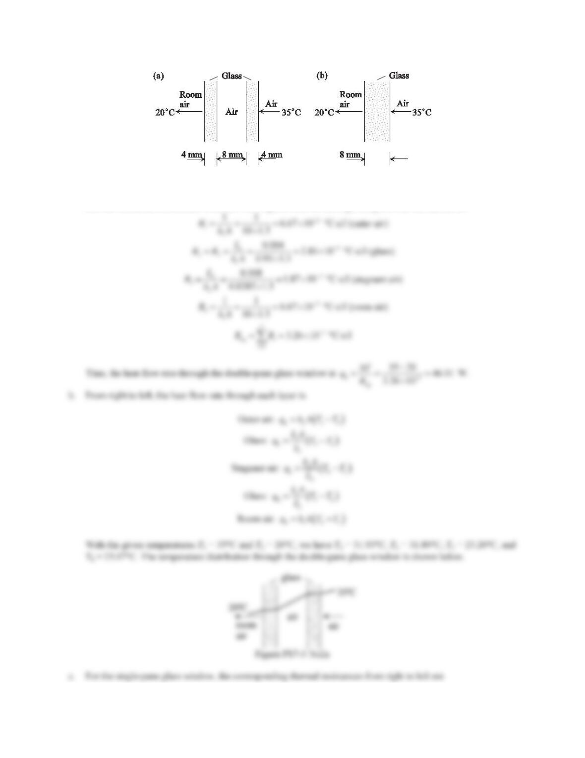
2. Consider heat transfer through a double-pane window as shown in Figure 7.31a. Two layers of glass with
thermal conductivity k1are separated by a layer of stagnant air with thermal conductivity k2. The inner surface
of the window is at temperature T1and exposed to room air with heat transfer coefficient h1. The outer surface
of the wall is at temperature T2and exposed to air with heat transfer coefficient h2. Assume that k1= 0.95
W/(m·°C), k2= 0.0285 W/(m·°C), h1=h2= 10 W/(m2·°C), T1= 20°C, and T2= 35°C. The thickness of each
glass layer is 4 mm, the thickness of the air layer is 8 mm, and the cross-sectional area of the window is 1.5 m2.
a. Determine the heat flow rate through the double-pane window.
b. Determine the temperature distribution through the double-pane window.
c. Repeat Parts (a) and (b) for the single-pane glass window shown in Figure 7.31b.
296
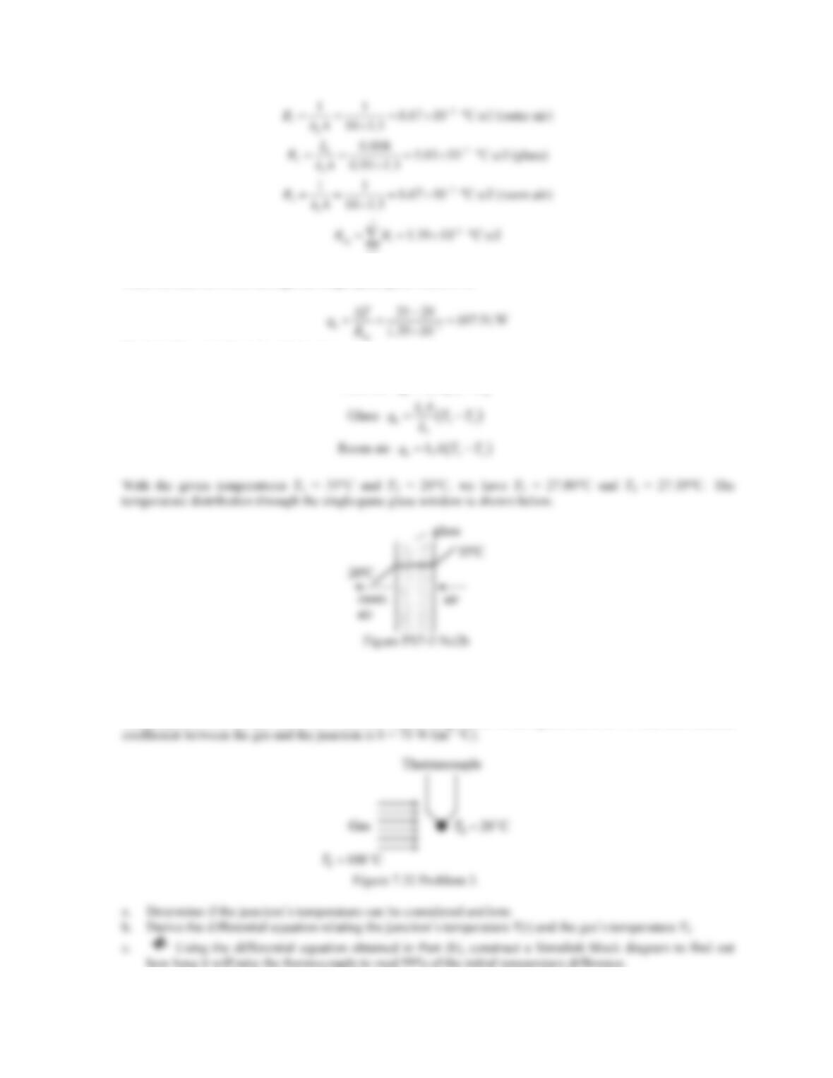
Figure 7.31 Problem 2.
Solution
a. The heat transfer through the double-pane glass window can be represented using a thermal circuit with five
thermal resistances connected in series. From right to left, the corresponding thermal resistances are
297
Thus, the heat flow rate through the single-pane glass window is
The heat flow rate through each layer is
Outer air:
qhATT
3. The junction of a thermocouple can be approximated as a sphere with a diameter of 1 mm. As shown in Figure
7.32, the thermocouple is used to measure the temperature of a gas stream. For the junction, the GHQVLW\LVȡ
8500 kg/m3, the specific heat capacity is c= 320 J/(kg·°C), and the thermal conductivity is k= 40 W/(m·°C).
The temperature of the gas Tfis 100°C and the initial temperature of the sphere T0is 20°C. The heat transfer