671
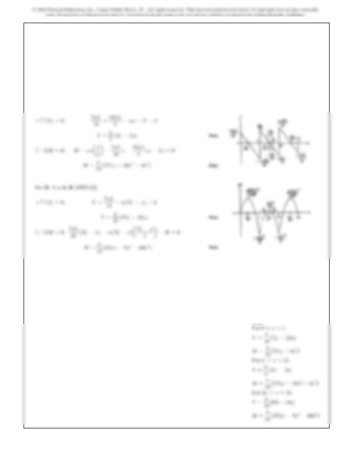
For [FBD (e)],
For [FBD (f)],
Ans.
2L<x◊3L
M=w
18 147Lx –60L
–9x
2
7wL
18 +10wL
9–wx–V=0+c©F
y
=0;
L◊x<2L
Ans:
For 0 …x6L
V=
w
18
(7L–18x)
7–57. Continued
672
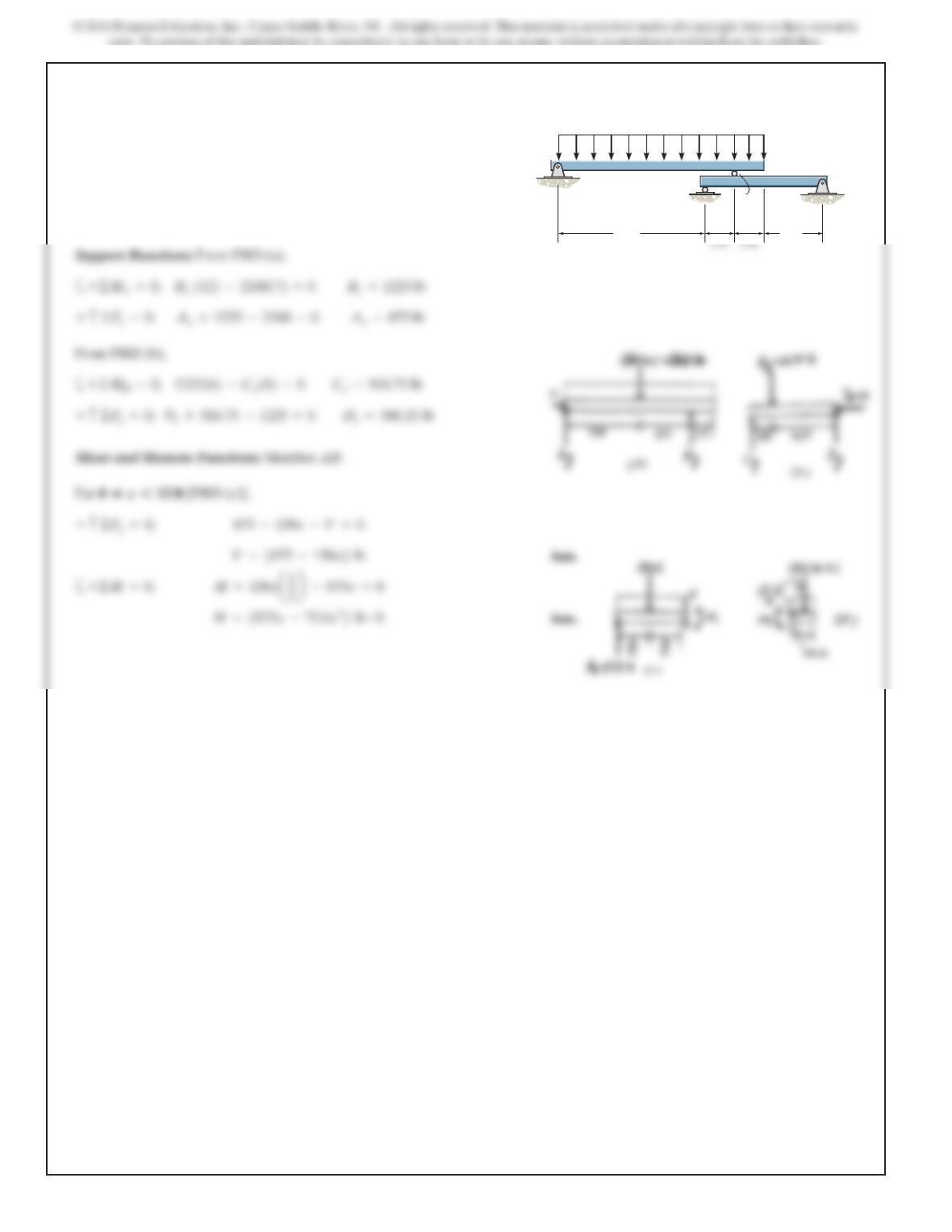
7–58.
Draw the shear and bending-moment diagrams for each of the
two segments of the compound beam.
A
CD
150 lb/ft
B
10 ft 4ft
2ft2ft
SOLUTION
Support Reactions: From FBD (a),
From FBD (b),
a
1225162–C
y
182=0C
y
=918.75 lb+©M
D
=0;
673
Ans:
Member AB:
For 0 …x612
ft
V=5875 –150x6 lb
V=52100 –150x6lb
7–58. Continued
Ans.
a
–150114 –x2a14 –x
2b–M=0+©M=0;
V=52100 –150x6lb
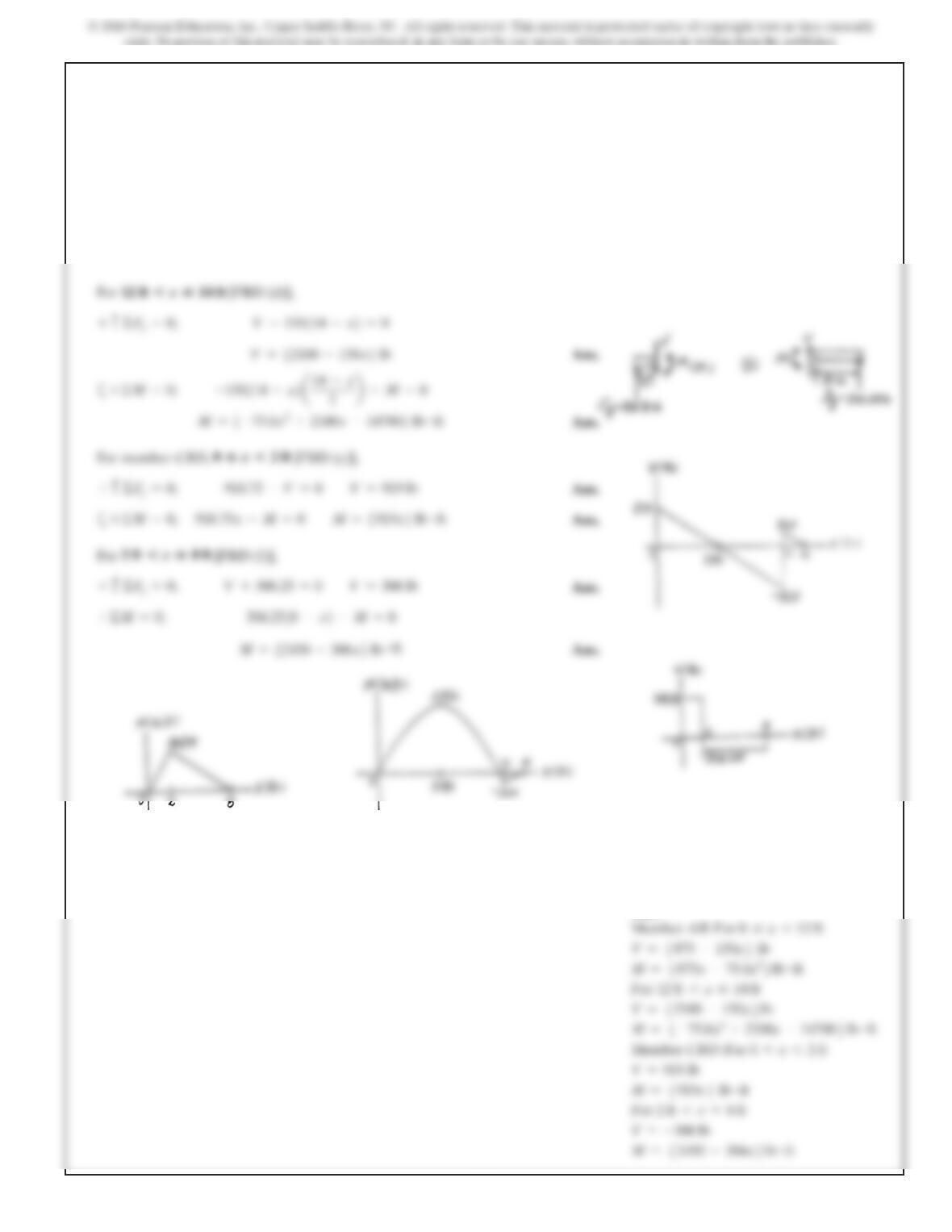
7–59.
Draw t
h
e s
h
ear an
d
moment
di
agrams for t
h
e
b
eam.
A
BC
9ft 4.5ft
30 lb/ft
180lbft
SOLUTION
:
:
9ft6x613.5 ft
2(3.33 x)(x)ax
3b–25 x=0
2(3.33 x)(x)–V=0
0…x69ft
675
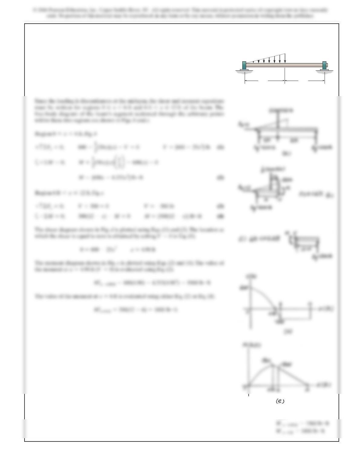
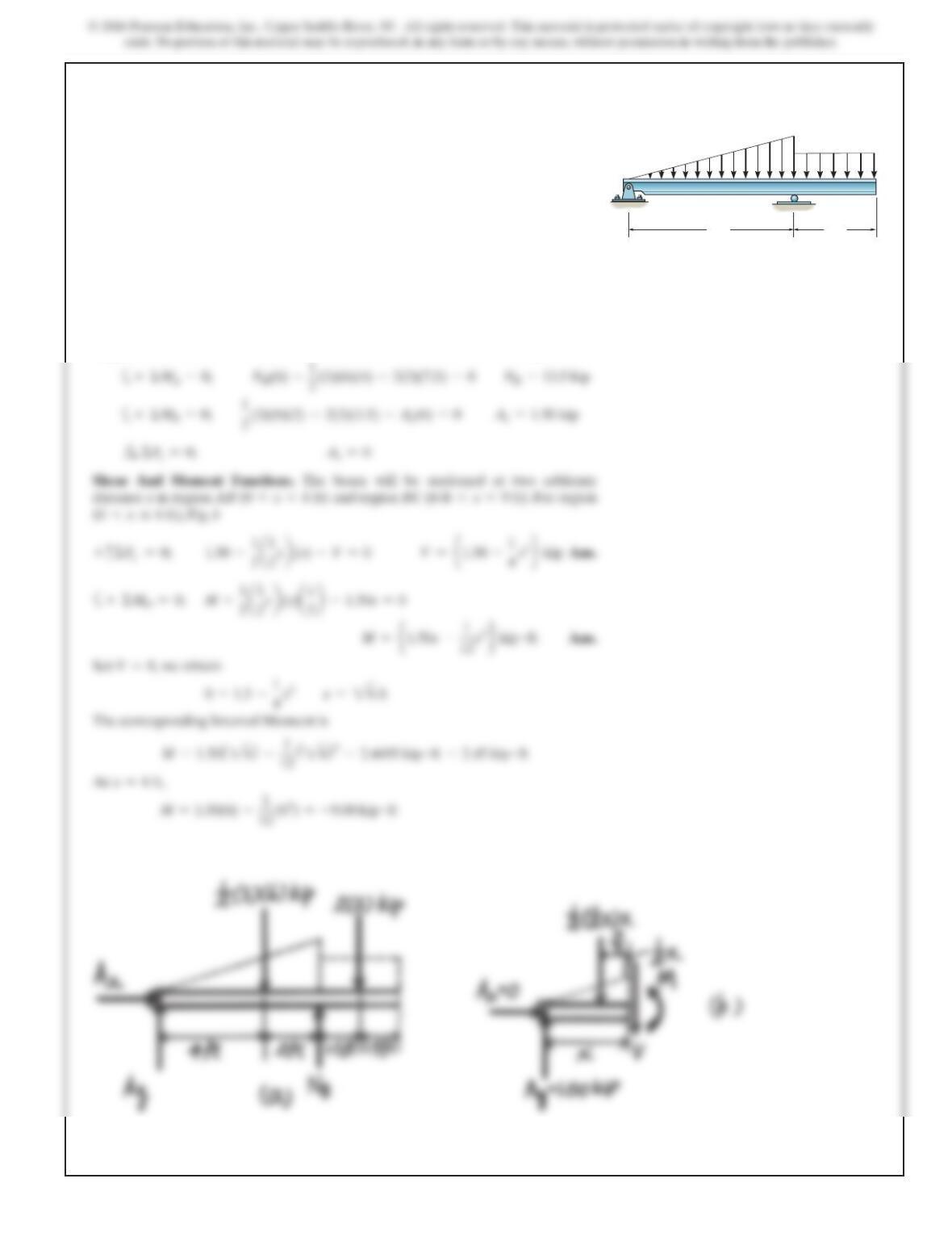
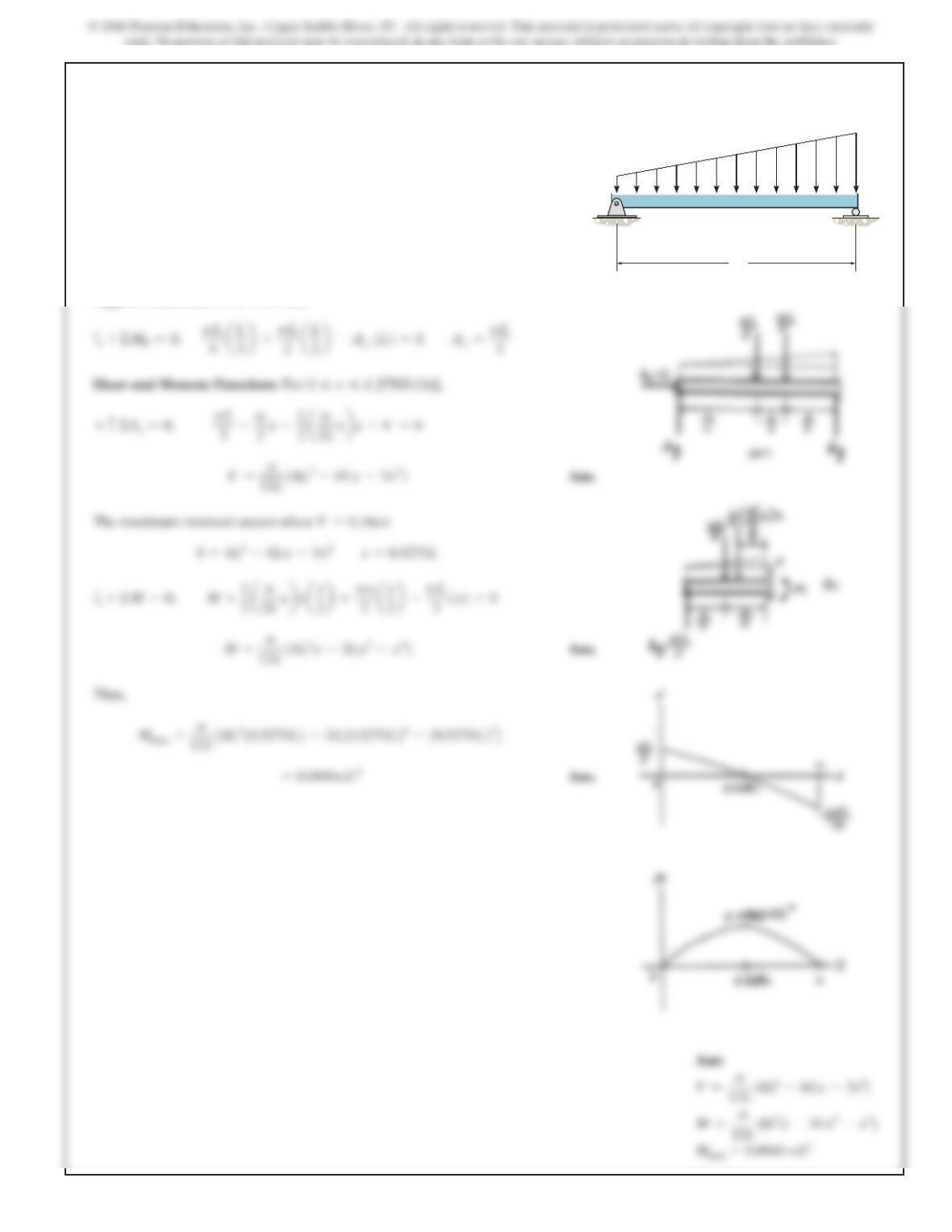
*7–60.
The shaft is supported by a smooth thrust bearing at Aand a
smooth journal bearing at B. Draw the shear and moment
diagrams for the shaft.
SOLUTION
Since the loading is discontinuous at the midspan, the shear and moment equations
must be written for regions and of the beam. The
free-body diagram of the beam’s segment sectioned through the arbitrary points
within these two regions are shown in Figs. band c.
Region ,Fig. b
Region ,Fig. c
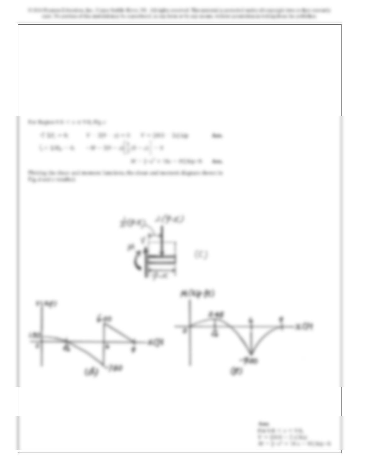
The shear diagram shown in Fig. dis plotted using Eqs. (1) and (3). The location at
which the shear is equal to zero is obtained by setting in Eq. (1).
The moment diagram shown in Fig. eis plotted using Eqs. (2) and (4). The value of
the moment at is evaluated using Eq. (2).
x=4.90 ft (V=0)
V=0
6 ft 6x…12 ft
0…x66 ft
6 ft 6x…12 ft0 …x66 ft
B
300 lb/ft
6 ft
A
6 ft
Ans:
676
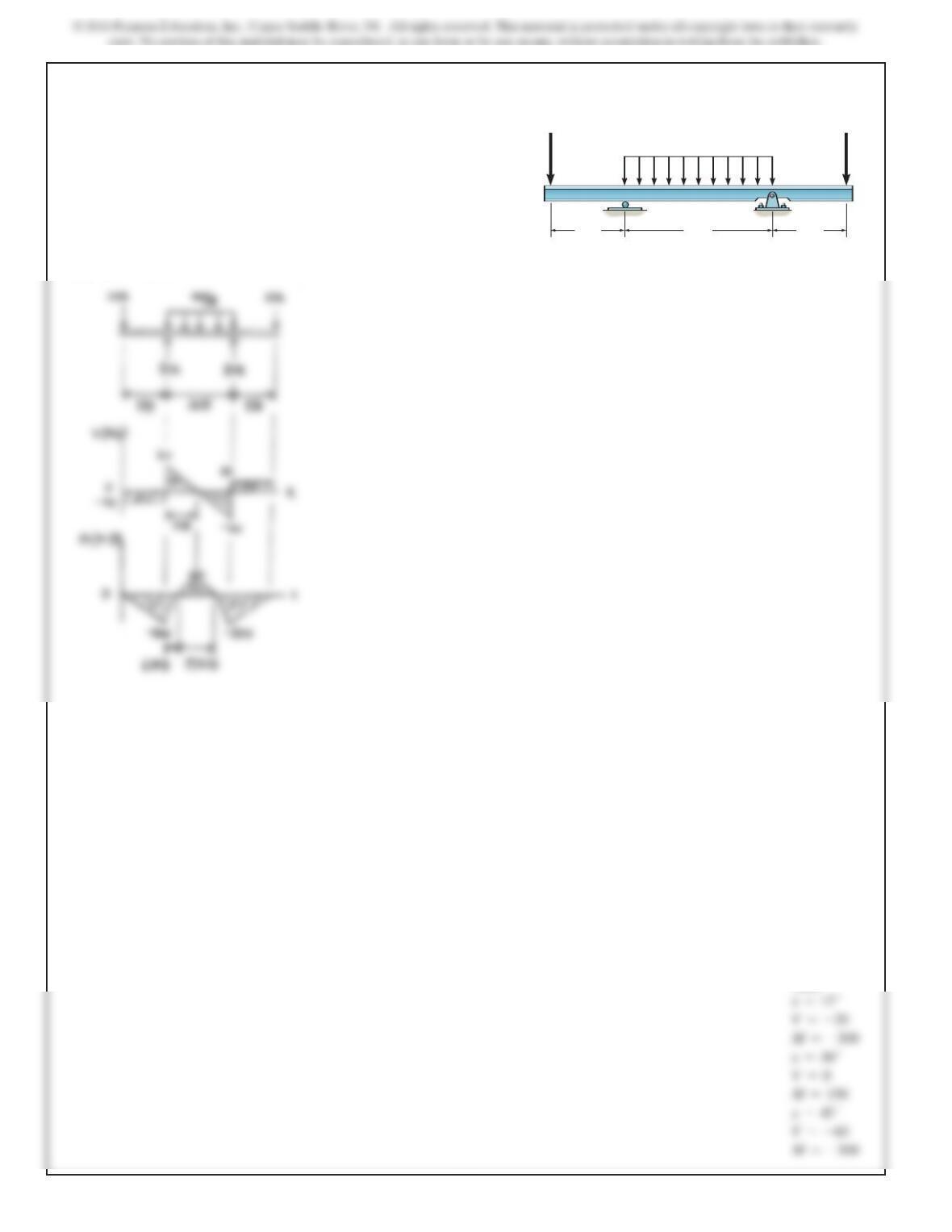
7–61.
SOLUTION
Draw the shear and moment diagrams for the beam.
4 kip/ft
20 kip 20 kip
15 ft
AB
30 ft 15 ft
Ans:
x=15–
V=–20
x=30+
x=45–
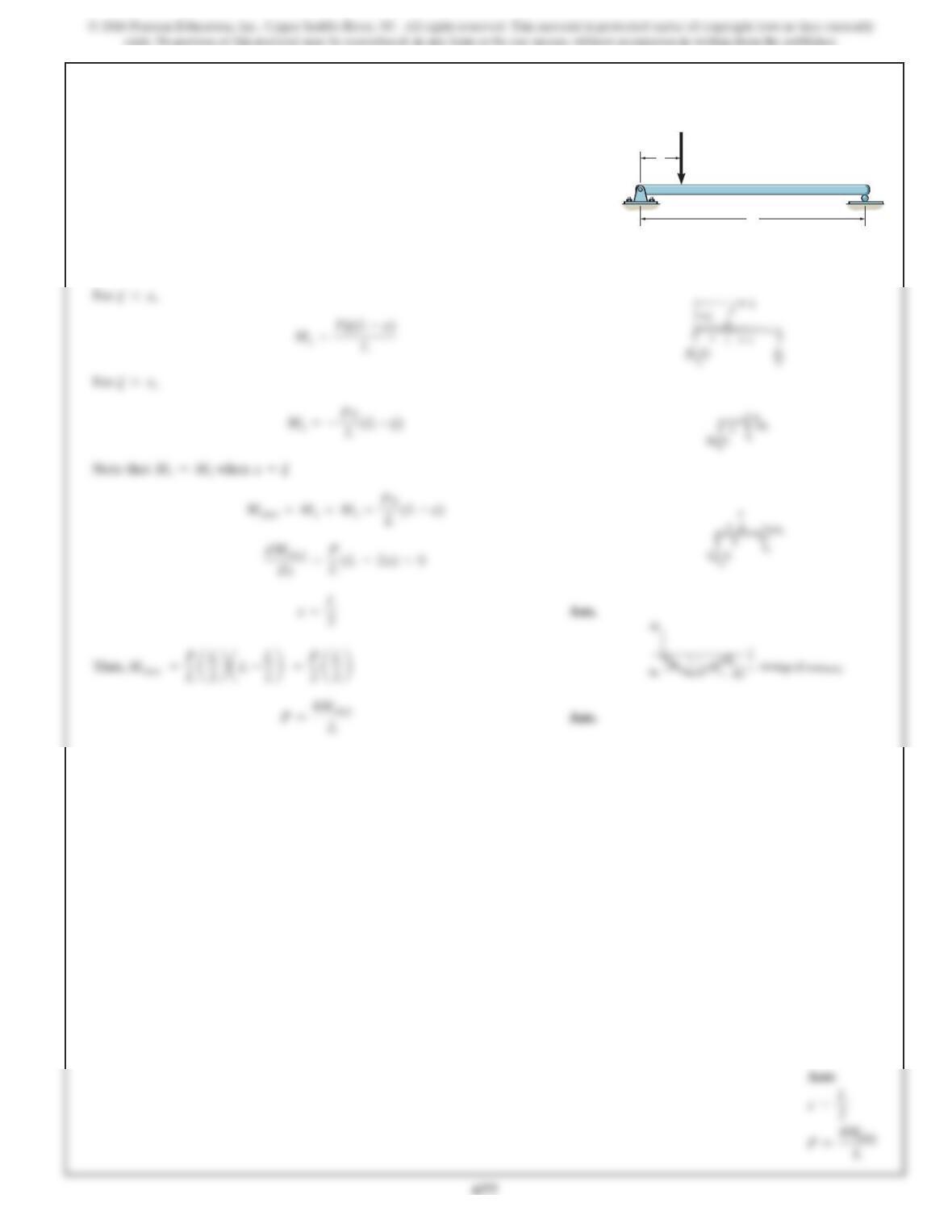
7–62.
SOLUTION
F
or ,
M1=Pj(L–x)
L
j6x
The beam will fail when the maximum internal moment is
Determine the position xof the concentrated force P
and its smallest magnitude that will cause failure
.
Mmax.
L
x
P
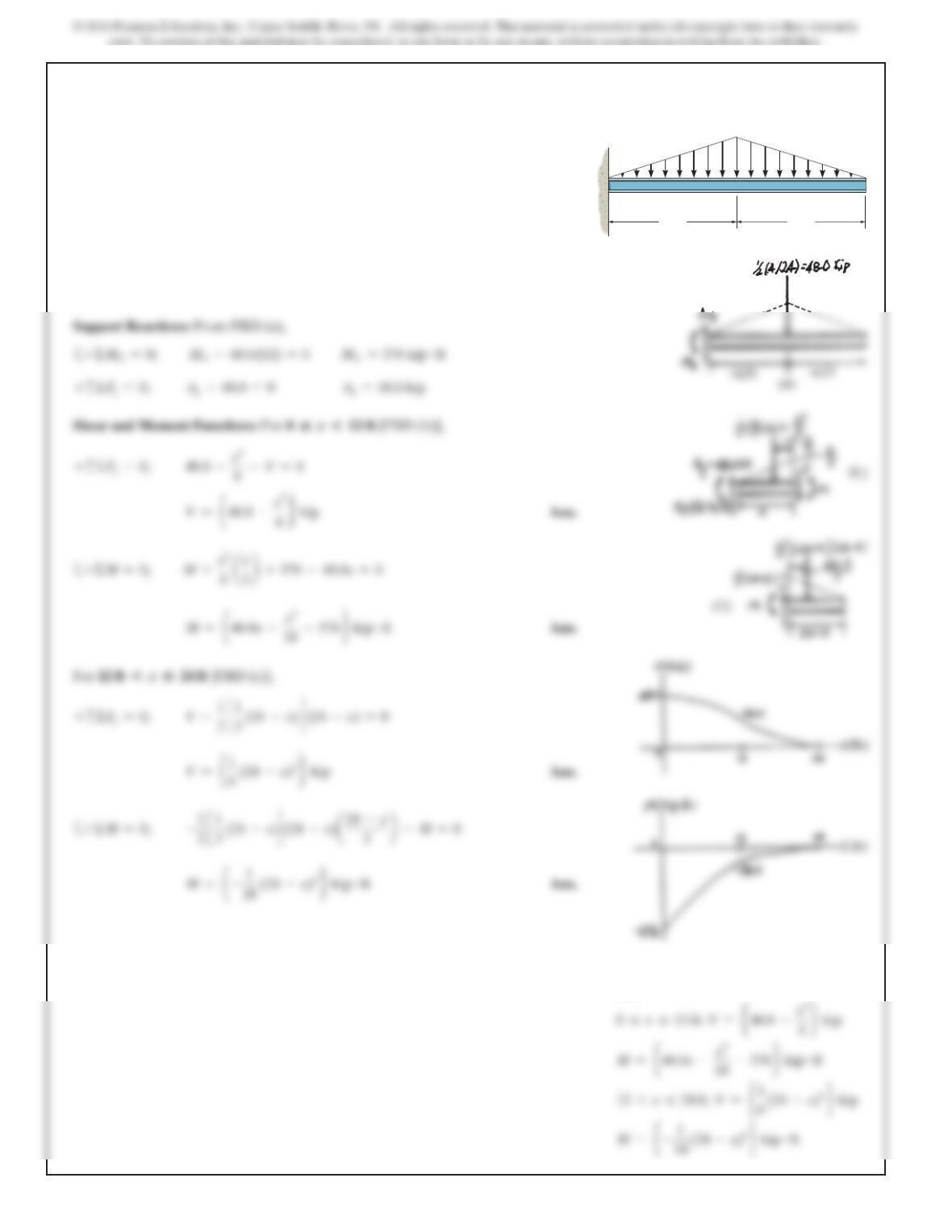
7–63.
Draw the shear and moment diagrams for the beam.
SOLUTION
Support Reactions: From FBD (a),
Shear and Moment Functions: For 0“x*12 ft [FBD (b)],
+
c
ΣFy=0; 48.0–x2
6–V=0
For 12 ft *x“24 ft [FBD (c)],
+
c
ΣFy=0; V–1
2
c1
3 (24 –x)d(24–x)=0
12 ft
A
12 ft
4 kip/ft
#
#
679
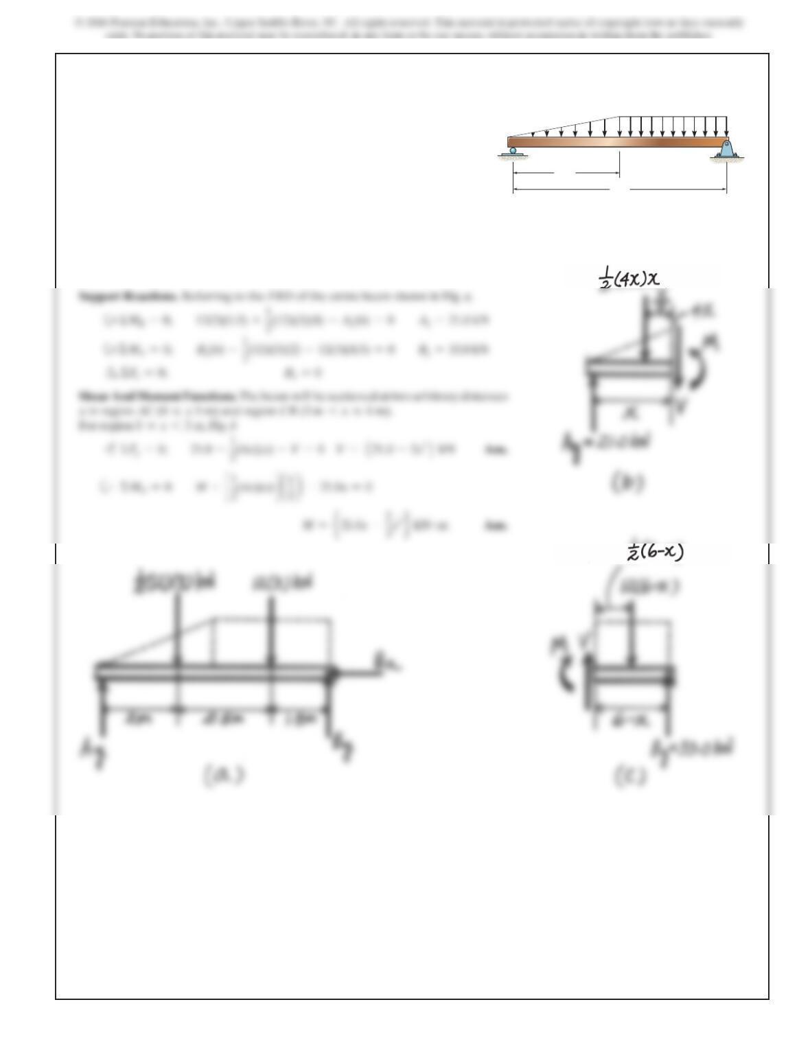
SOLUTION
Support Reactions. Referring to the FBD of the entire beam shown in Fig. a,
Shear And Moment Functions. The beam will be sectioned at two arbitrary
distance x in region AB
(0 …x66 ft)
and region BC
(6 ft 6x…9 ft)
. For region
(0 6x…6 ft)
, Fig. b
+
c
ΣF
y
=0;
1.50 –1
2
a
1
2
x
b
(x)–V=0 V=
e
1.50 –1
4
x2
f
kip Ans.
The corresponding Internal Moment is
M=1.50
(
2
6
)
–
1
12
(
2
6
)
3=2.4495 kip
#
ft =2.45 kip
#
ft
*7–64.
Draw the shear and moment diagrams for the beam.
A
BC
6 ft 3 ft
3 kip/ft
2 kip/ft
680
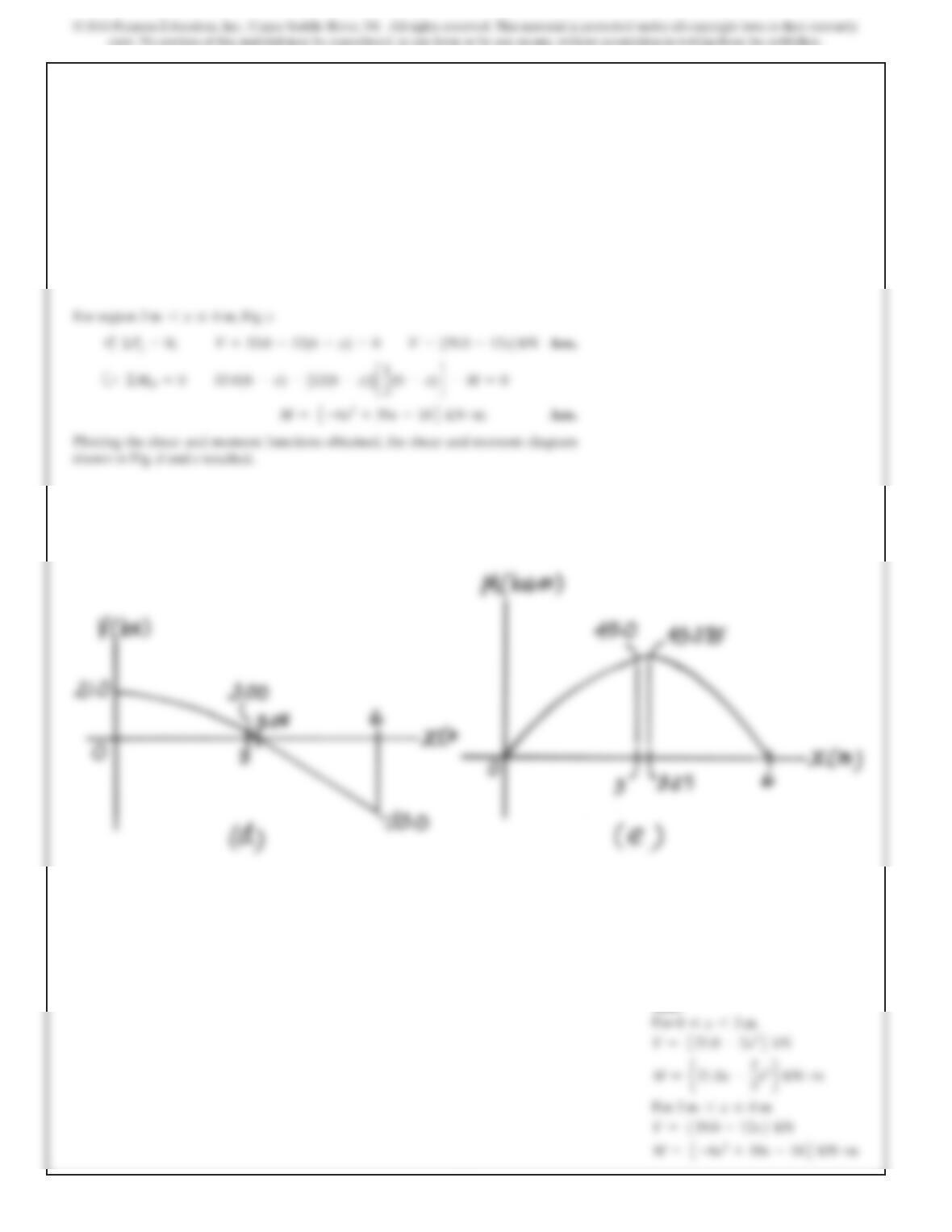
Ans:
For
6 ft 6x…9 ft,
For Region
6 ft 6x…9 ft,
Fig. c
*7–64. Continued
681
SOLUTION
Support Reactions. Referring to the FBD of the entire beam shown in Fig. a,
Shear And Moment Functions. The beam will be sectioned at two arbitrary distances
x in region AC
(0 …x 3 m)
and region CB
(3 m 6x…6 m).
For region
0…x63 m
, Fig. b
7–65.
Draw the shear and moment diagrams for the beam.
3 m
6 m
12 kN
/
m
AB
C
682
7–65. Continued
Ans:
For
0…x63 m
683
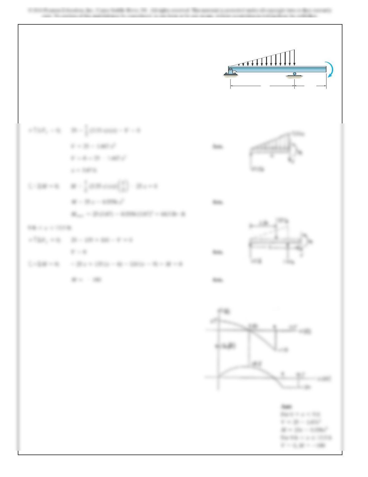
7–66.
Draw the shear and moment diagrams for the beam.
SOLUTION
Support Reactions:
From FBD (a),
Shear and Moment Functions:
For [FBD (b)],
The maximum moment occurs when then
Thus,
0=4L
2
–6Lx –3x
2
x=0.5275L
V=0,
wL
3–w
2x–1
2aw
2Lxbx–V=0+c©F
y
=0;
0…x…L
w
L
w
––
2
AB
Ans:
V=
w
12L
(4L
2–6Lx –3x2)
684
Ans:
SOLUTION
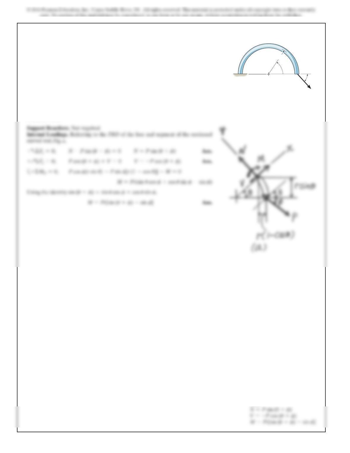
Support Reactions. Not required
Internal Loadings. Referring to the FBD of the free and segment of the sectioned
curved rod, Fig. a,
7–67.
Determine the internal normal force, shear force, and
moment in the curved rod as a function of
uu
. The force P
acts at the constant angle ff.
P
r
u
f
685
*7–68.
Ans:
686
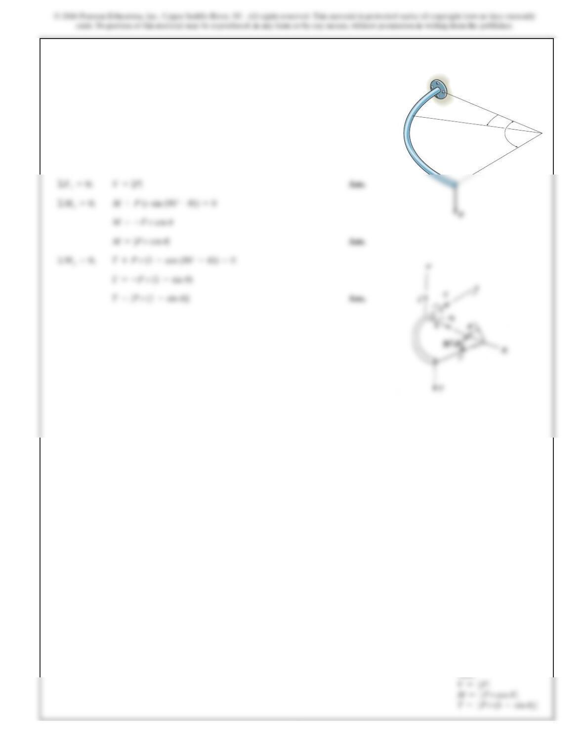
7–69.
Express t
h
e
i
nterna
l
s
h
ear an
d
moment components act
i
ng
in the rod as a function of y, where 0 …y…4 ft.
y
z
x
y
4ft2ft
4lb/ft
SOLUTION
Shear and Moment Functions:
Ans.
©F
z
=0; V
z
–4(4 –y)–8.00 =0
©F
x
=0; V
x
=0
Ans:
687
SOLUTION
Support Reactions. Referring to the FBD of the simply supported beam shown in
Fig. a
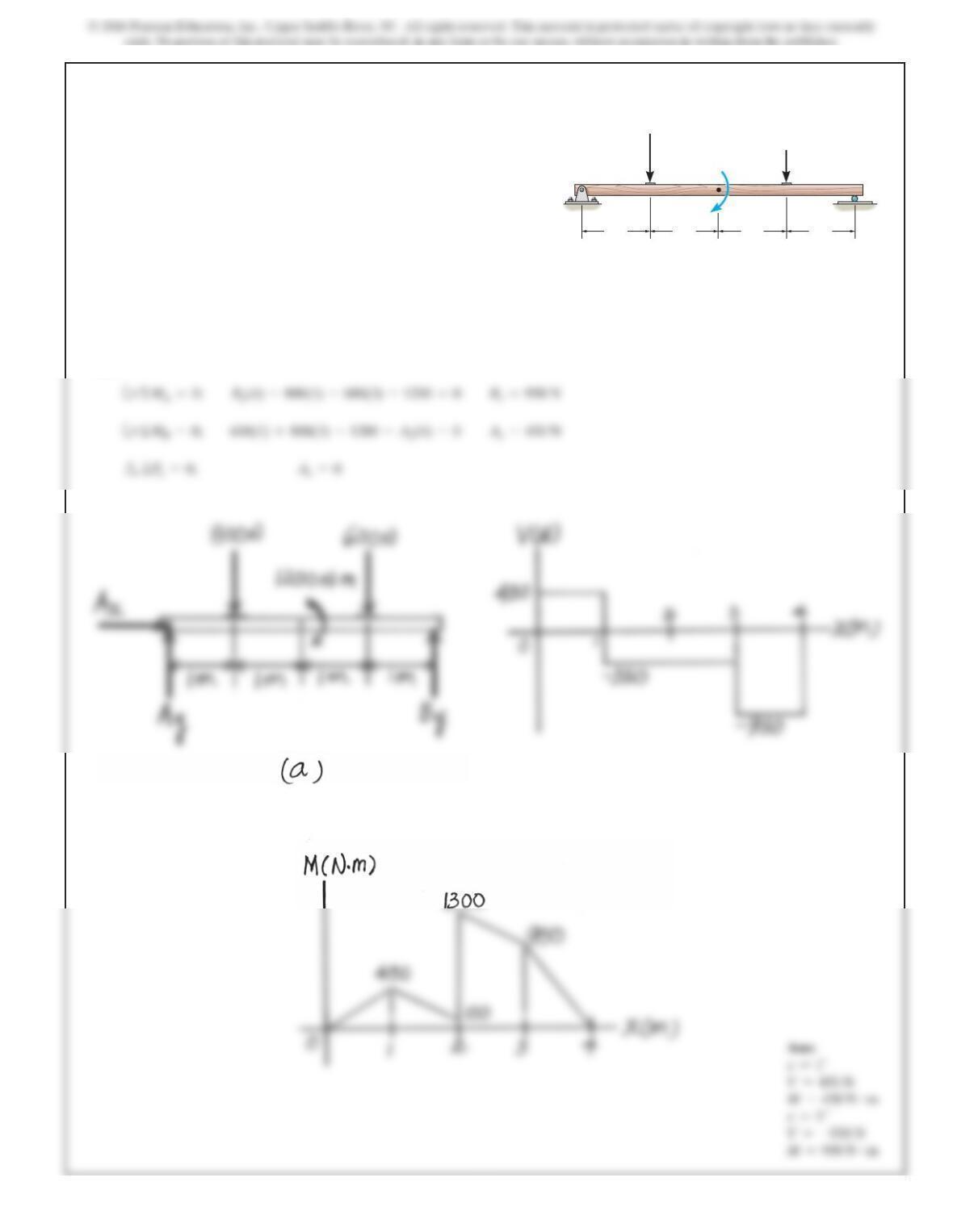
7–70.
Draw the shear and moment diagrams for the beam.
1 m1 m1
m1
m
800 N
600 N
A B
1200 N m
SOLUTION
Support Reactions. Referring to the FBD of the beam shown in Fig. a
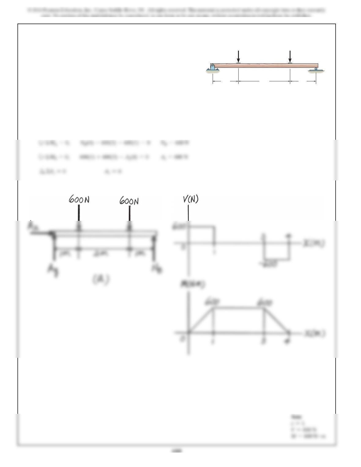
7–71.
Draw the shear and moment diagrams for the beam.
1 m 2 m 1 m
600 N 600 N
AB
689
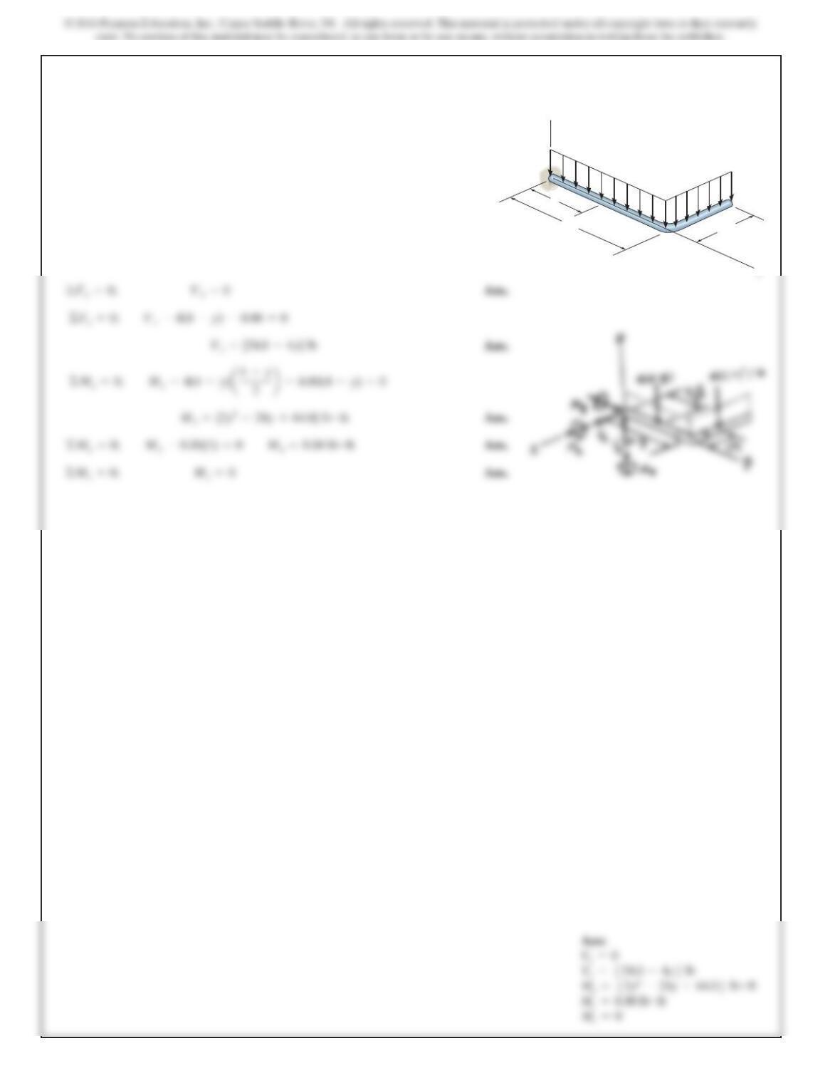
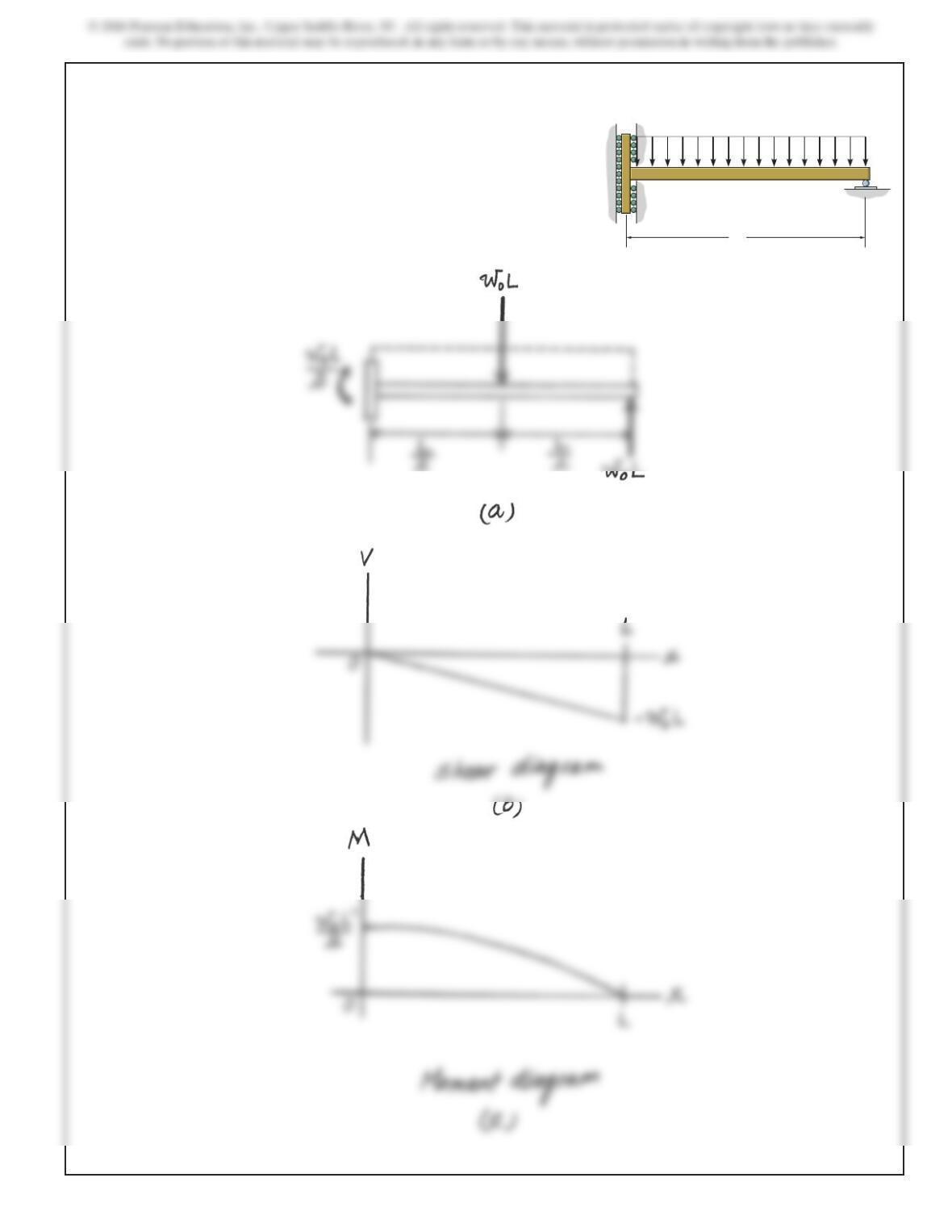
*7–72.
Draw the shear and moment diagrams for the beam. The
support at Aoffers no resistance to vertical load.
SOLUTION
L
A B
w
0
690
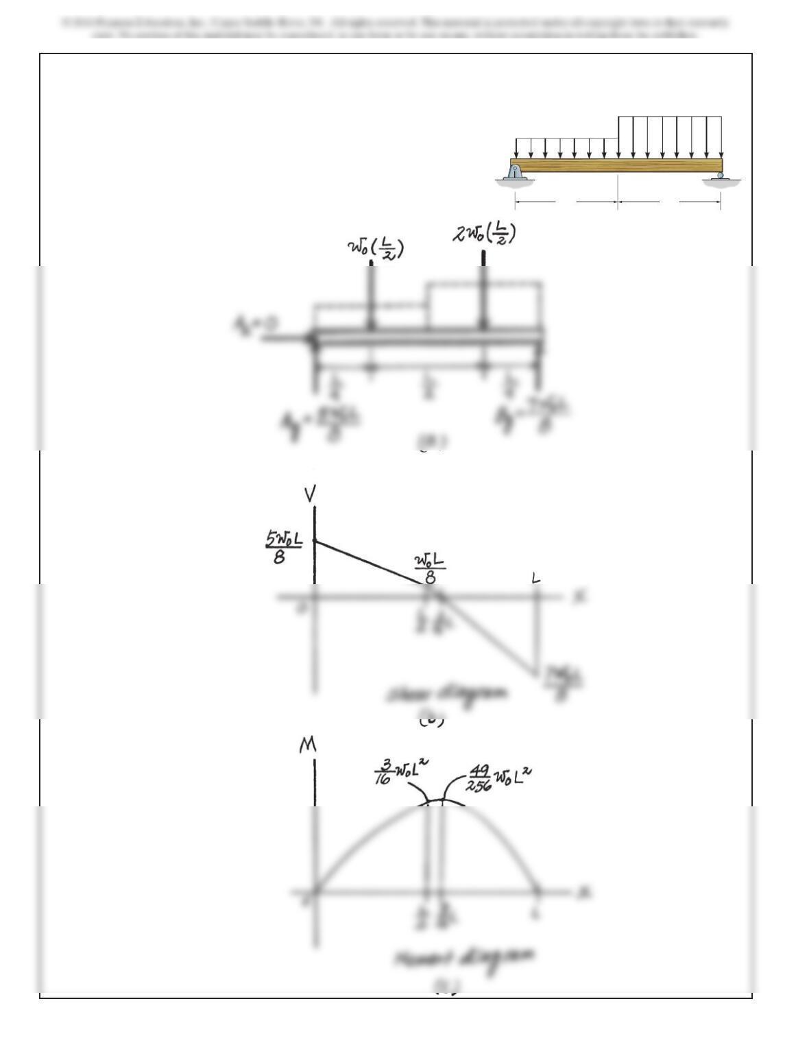
7–73.
Draw the shear and moment diagrams for the simply-
supported beam.
SOLUTION
w
0
2w
0
L/2L/2
AB