691
SOLUTION
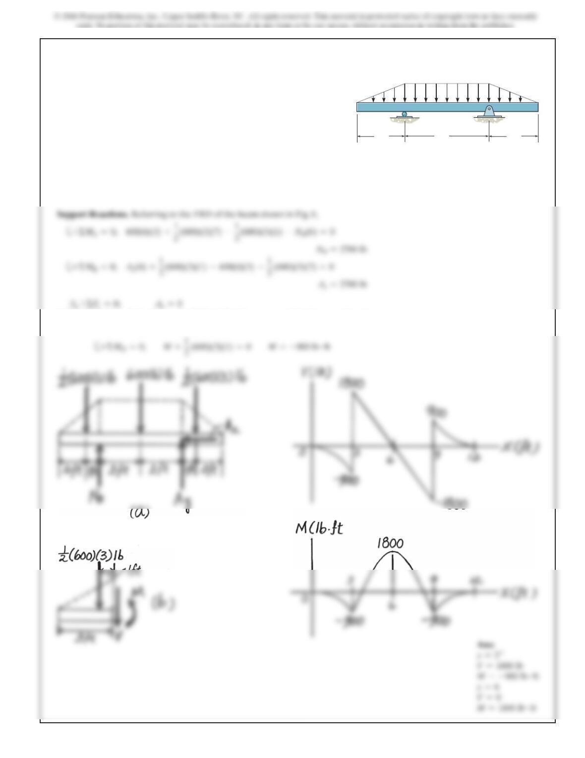
Support Reactions. Referring to the FBD of the shaft shown in Fig. a,
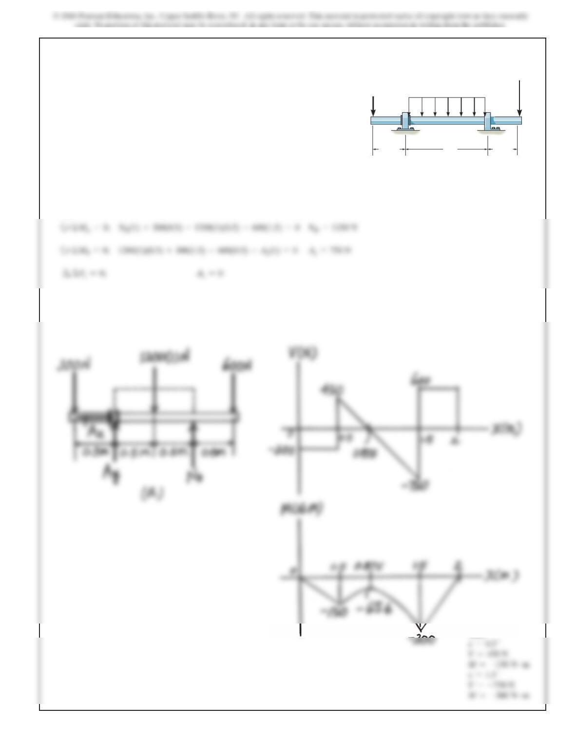
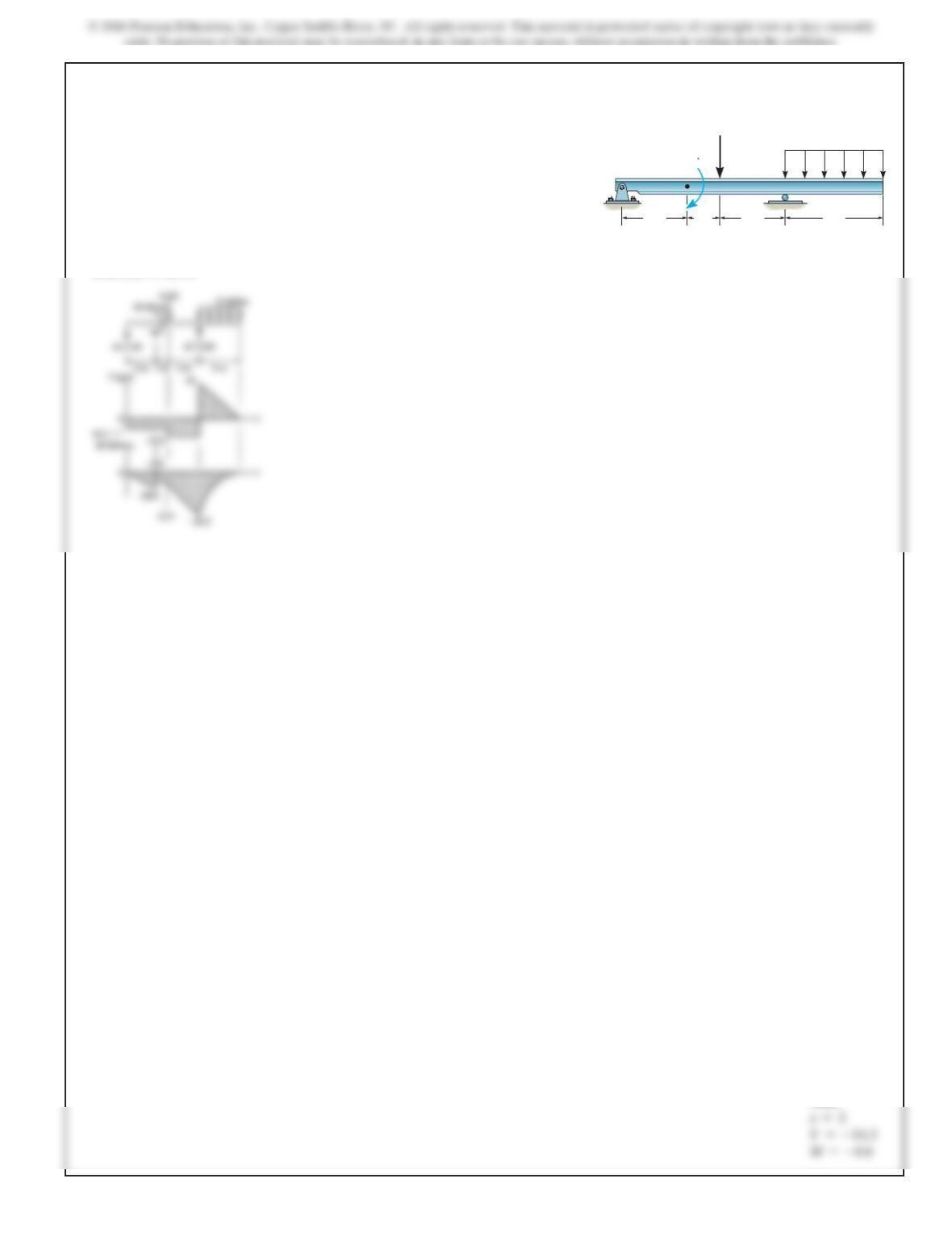
7–74.
Draw the shear and moment diagrams for the beam. The
supports at A and B are a thrust bearing and journal
bearing, respectively.
0.5 m 0.5 m
1 m
1200 N/m
A
300 N
600 N
B
7–75.
Draw the shear and moment diagrams for the beam.
SOLUTION
Support Reactions:
ABC
250 N/m
3m
SOLUTION
Support Reaction. Referring to the FBD of the beam shown in Fig. a,
a
+ΣMA=0;
NB(6) –15(2) –20 –10(2)(5) =0
NB=25.0 kN
+ΣMB=0;
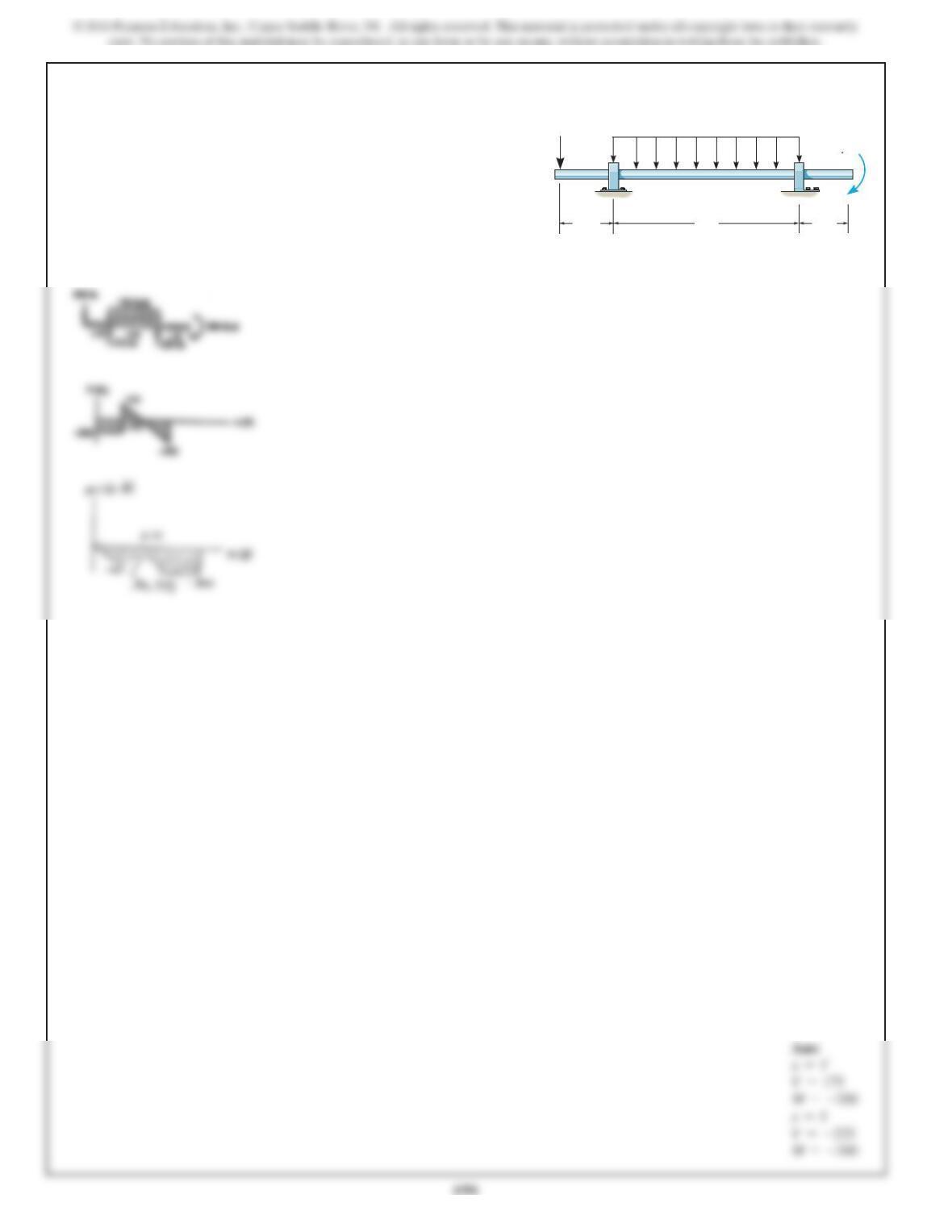
*7–76.
Draw the shear and moment diagrams for the beam.
2 m1 m1 m
15 kN
AB
10 kN/m
20 kN m
2 m
V=10.0 kN
V=–5.00 kN
SOLUTION
Support Reactions. Referring to the FBD of the beam shown in Fig. a,
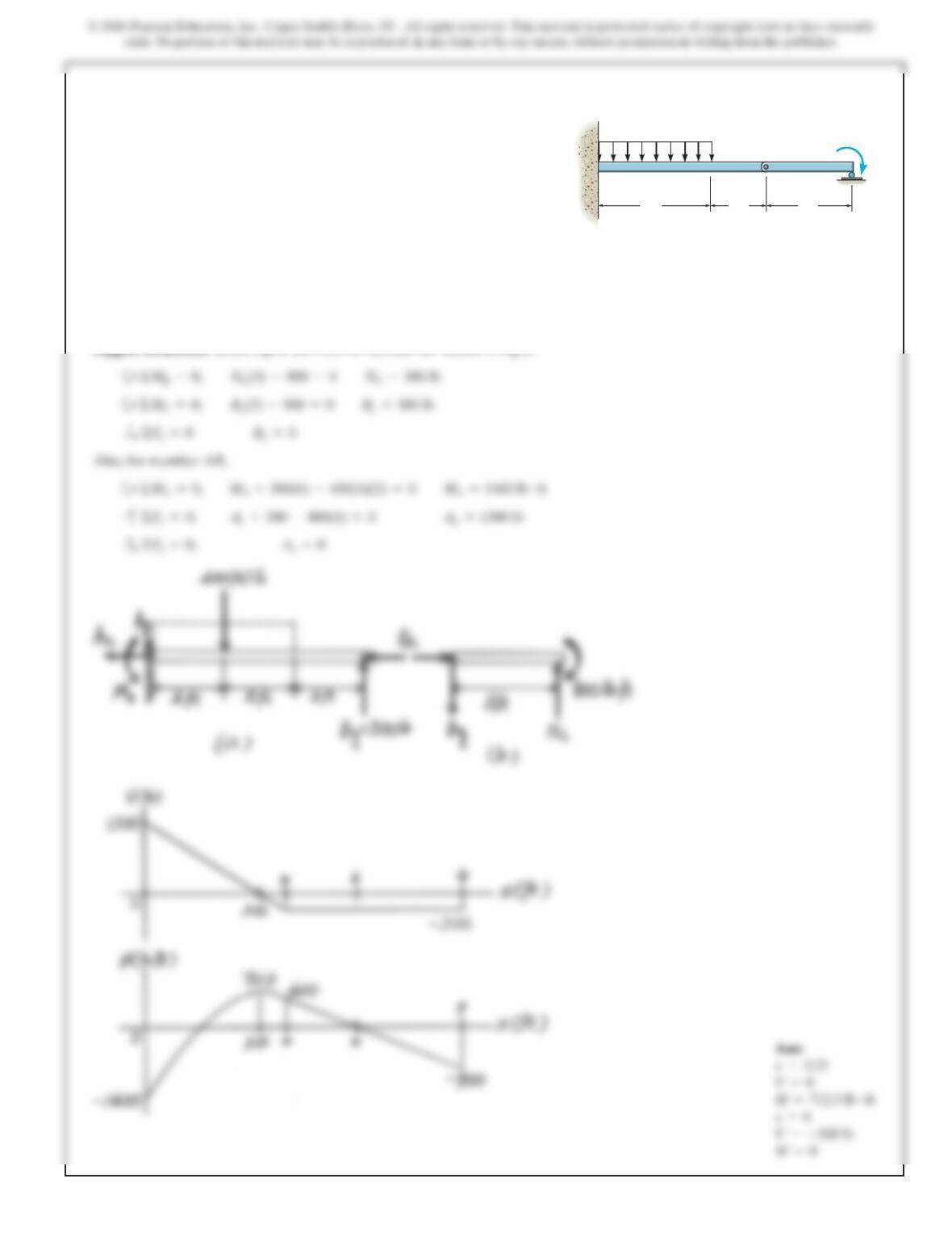
7–77.
Draw the shear and moment diagrams for the beam.
2 kip
/
ft
10 ft
AB
20 ft 10 ft
50 kip
ft
50 kip ft
V=20.0 kip
7–78.
Draw the shear and moment diagrams for the beam.
SOLUTION
2m 1m 2m
8kN
AB
15 kN/m
20 kN m
3m
V=–14.3
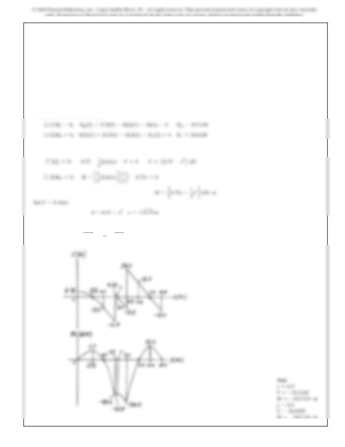
7–79.
SOLUTION
Draw the shear and moment diagrams for the shaft. The
support at Ais a journal bearing and at Bit is a thrust
bearing.
1ft4ft1ft
100 lb/ft
A300 lb ft
200lb
B
697
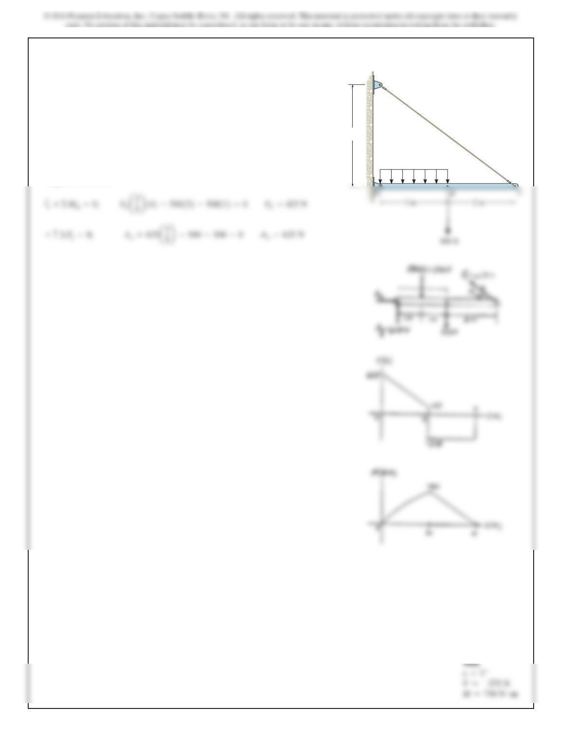
SOLUTION
Support Reactions. Referring to the FBD of member BC shown in Fig. a,
a
+ΣMB=0;
NC(3) –900 =0
NC=300 lb
Bx=0
Also, for member AB,
a
+ΣMA=0;
MA+300(6) –400(4)(2) =0
MA=1400 lb #ft
Ax=0
*7–80.
Draw the shear and moment diagrams for the beam.
4 ft 2 ft 3 ft
400 lb/ft 900 lb ft
ABC
698
SOLUTION
Support Reactions. Referring to the FBD of member EF, Fig. c
+ΣME=0;
E
=18.0 kN
Also, for member AB, Fig. a
a
+ΣMA=0;
By(4.5) –
1
2
(9)(4.5)(3) =0
B
y
=13.5 kN
A
=6.75 kN
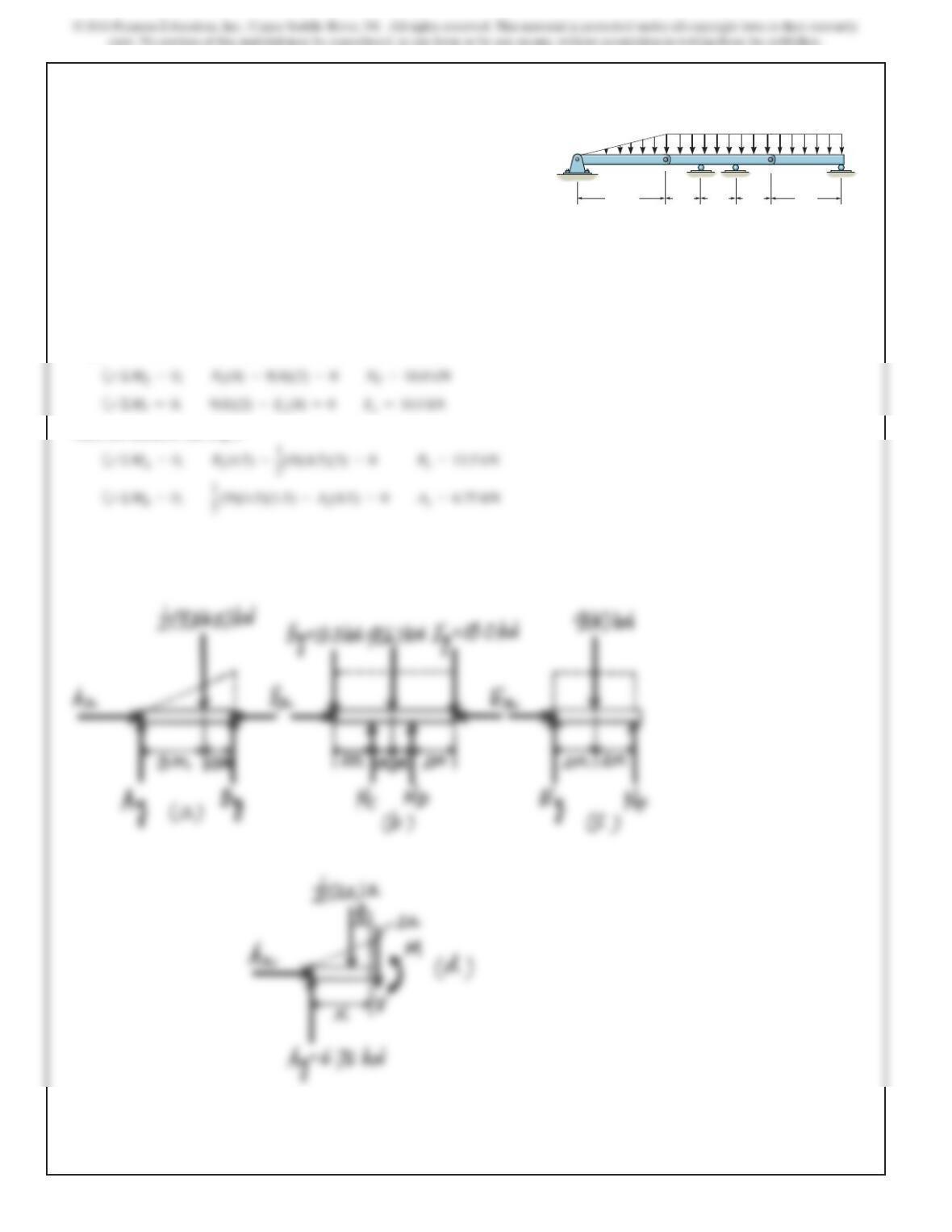
7–81.
The beam consists of three segments pin connected at B
and E. Draw the shear and moment diagrams for the beam.
4.5 m 2 m 2 m 2 m 4 m
9 kN
/
m
A
B
CD
E
F
699
Finally, for member BCDE, Fig. b
Shear And Moment Functions. Referring to the FBD of the left segment of member
AB sectioned at an distance x, Fig. d,
The corresponding moment is
M=6.75
(
2
6.75
)
–
1
3
1
2
6.75
2
3=11.69 kN
#
m=11.7 kN
#
m
7–81. Continued
M=–54.0 kN #m
700
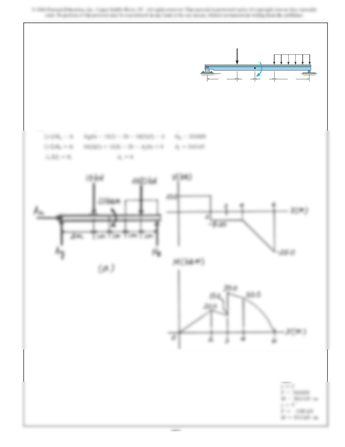
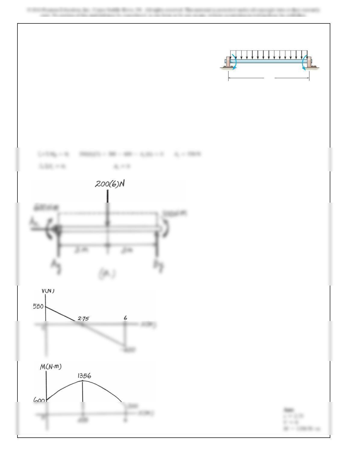
7–82.
Draw the shear and moment diagrams for the beam. The
supports at A and B are a thrust and journal bearing,
respectively.
SOLUTION
Support Reactions. Referring to the FBD of the shaft shown in Fig. a,
a
+ΣMA=0;
B
y
(6) +300 –200(6)(3) –600 =0
B
y
=650 N
+ΣMB=0;
A
AB
200 N/m
6 m
600 N m 300 N m
701
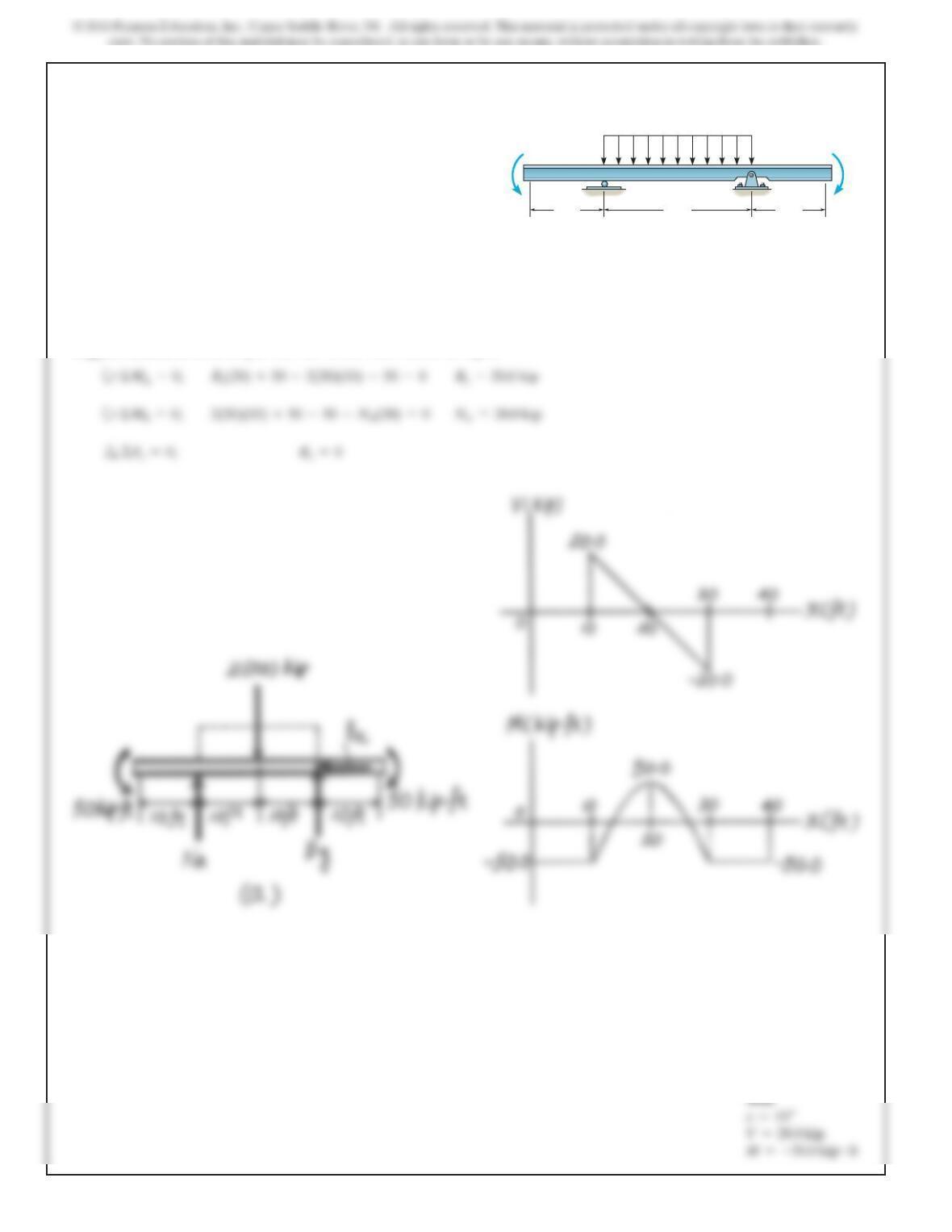
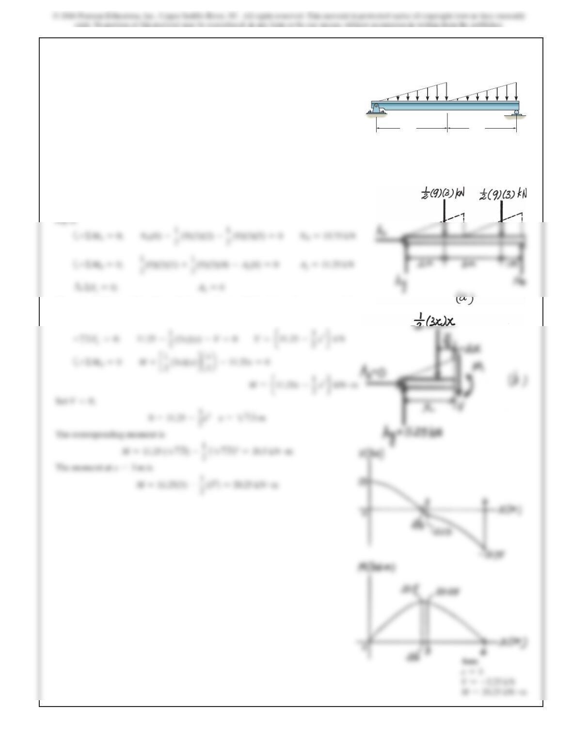
7–83.
Draw the shear and moment diagrams for the beam. 9 kN/m9 kN/m
A B
3 m 3 m
SOLUTION
Support Reactions. Referring to the FBD of the simply supported beam shown in
Shear And Moment Functions. Referring to the FBD of the left segment of the
beam sectioned at a distance x within region
0 6x…3 m.
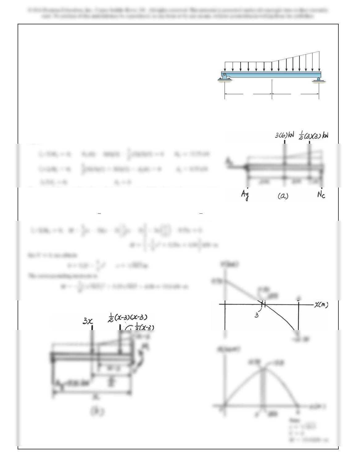
702
SOLUTION
Support Reactions. Referring to the FBD of the simply supported beam shown in
Fig. a,
Shear And Moment Functions. Referring to the FBD of the left segment of the
beam sectioned at a distance x within region BC
(3 m 6x…6 m)
,
+
c
ΣF
y
=0;
9.75 –3x–
1
2
(x–3)(x–3) –V=0 V=
e
5.25 =
1
2
x2
f
kN
*7–84.
Draw the shear and moment diagrams for the beam.
3 m 3 m
3 kN/m
6 kN/m
A
B
C
703
SOLUTION
Internal Loadings. Referring to the FBD of the left segment of the beam sectioned
at
x=3 ft
shown in Fig. a, the internal moment at
x=3 ft
is
7–85.
Draw the shear and moment diagrams for the beam.
6 ft
3 ft
3 ft
600 lb/ft
BA
704
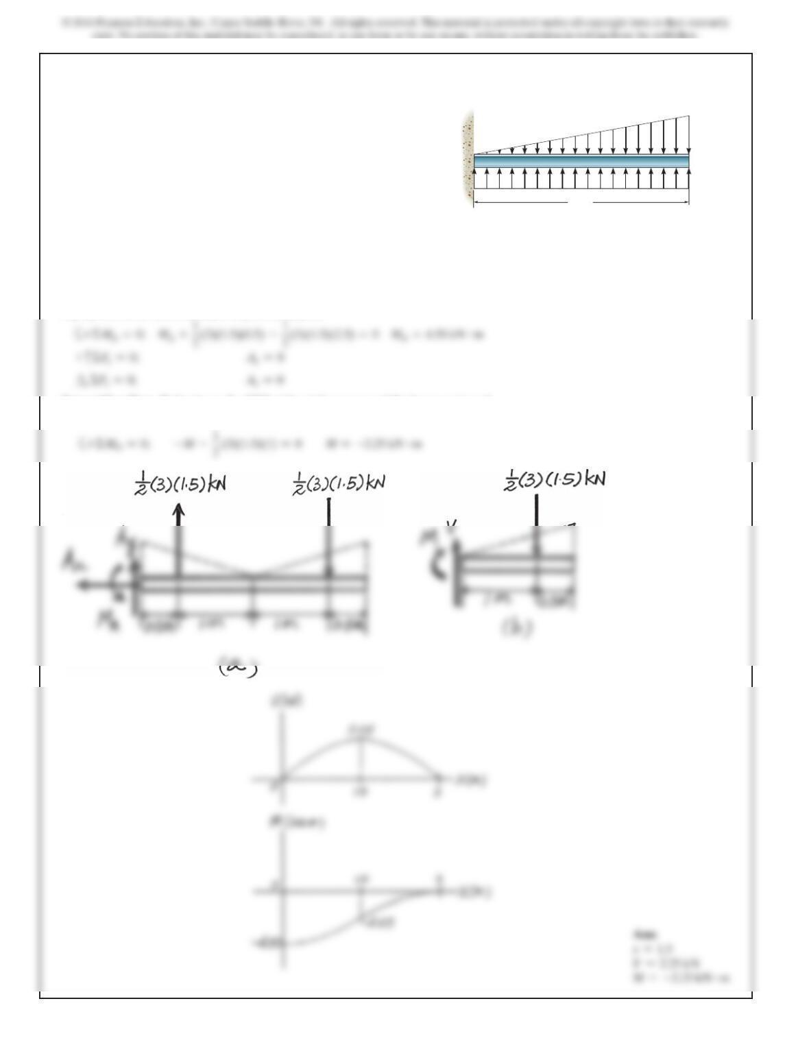
SOLUTION
Support Reactions. The FBD of the beam acted upon the equivalent loading (by
superposition) is shown in Fig. a. Equilibrium gives
Internal Loadings. Referring to the FBD of the right segment of the beam sectioned
at
x=1.5 m
, the internal moment at this section is
7–86.
Draw the shear and moment diagrams for the beam.
3 m
3 kN/
m
6 kN/m
A
Ans:
x=1.5
705
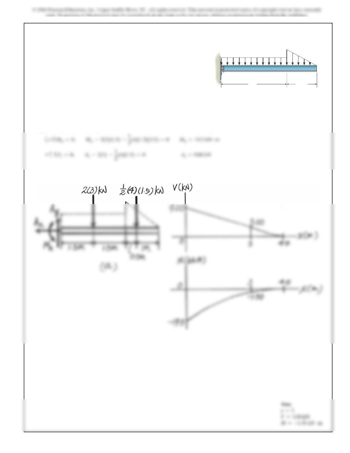
SOLUTION
Support Reactions. Referring to the FBD of the cantilevered beam shown in Fig. a.
7–87.
Draw the shear and moment diagrams for the beam.
3 m 1.5 m
2 kN/m
4 kN/m
A
B
M=–1.50 kN #m
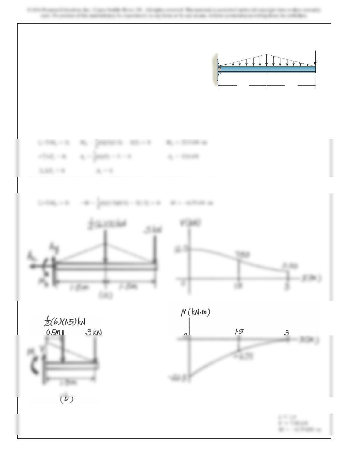
SOLUTION
Support Reactions. Referring to the FBD of the cantilevered beam shown in Fig. a.
Internal Loadings. Referring to the FBD of the right segment of the beam sectioned
at
x=1.5 m
, the internal moment at this section is
*7–88.
Draw the shear and moment diagrams for the beam.
1.5 m
1.5 m
3 kN
6 kN/m
AB
Ans:
V=7.50 kN

707
SOLUTION
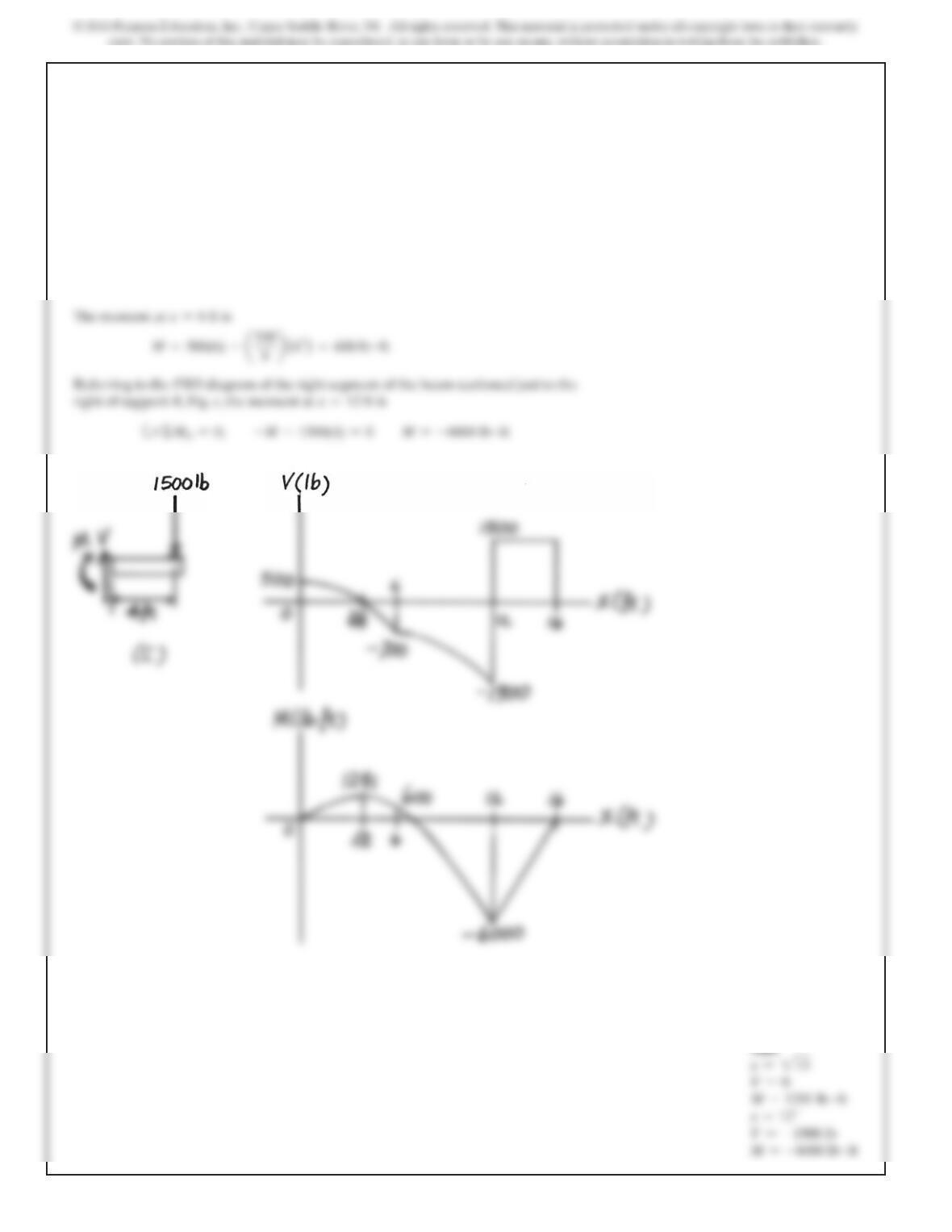
Support Reactions. Referring to the FBD of the overhang beam shown in Fig. a
Shear And Moment Functions. Referring to the FBD of the left segment of the
beam sectioned at a distance x within region
0…x66 ft,
Fig. b
+
c
ΣF
y
=0;
500 –
1
2
a200
3
x
b
x–V=0 V=
e
500 –
100
3
x2
f
lb
2
3
The corresponding moment is
M=500
2
15 –
100
9
1
2
15
2
3=1291 lb
#
ft
6 ft
400 lb/ft 400 lb/ft
1500 lb
6 ft 4 ft
A
B
7–89.
Draw the shear and moment diagrams for the beam.
708
7–89. Continued
The moment at
x=6 ft
is
x=12 ft
Ans:
x=215
V=0
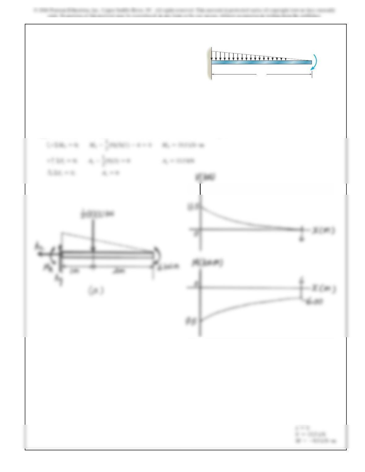
SOLUTION
Support Reactions. Referring to the FBD of the cantilivered beam shown in Fig. a,
7–90.
Draw the shear and moment diagrams for the beam.
3 m
9 kN/m
6 kN m
B
A
V=13.5 kN
710
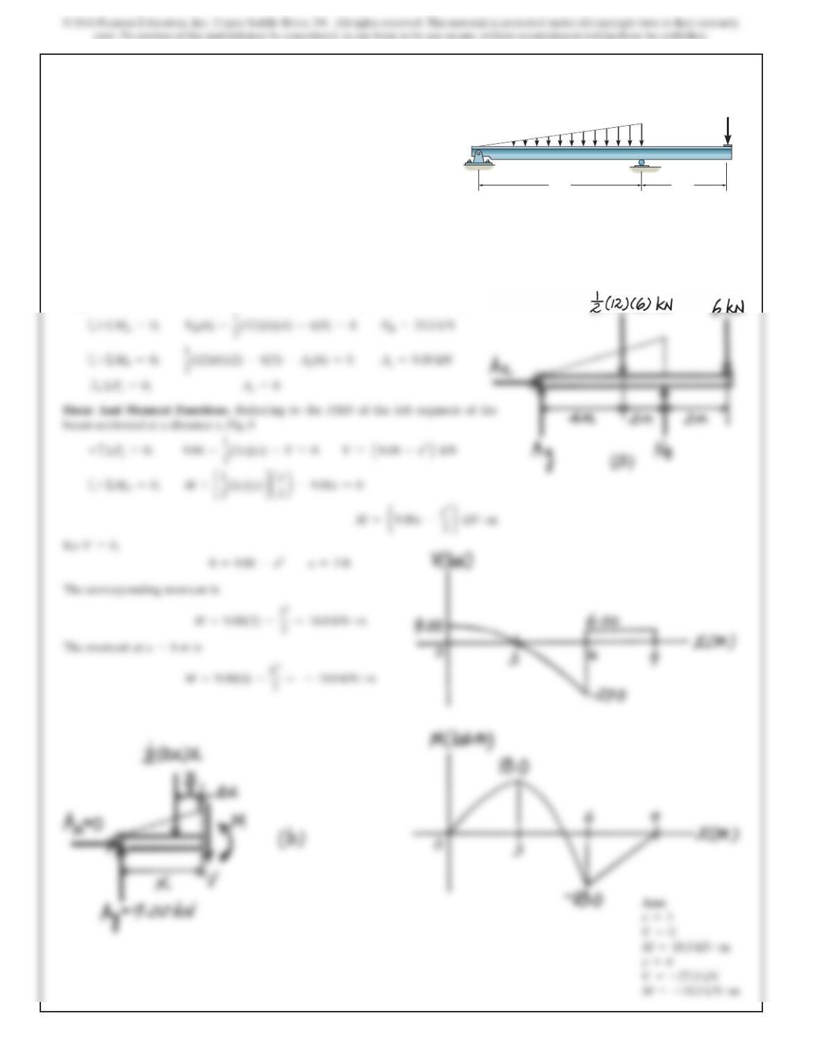
7–91.
Draw the shear and moment diagrams for the beam. 12 kN/m
A
BC
6 m 3 m
6 kN
SOLUTION
Support Reactions. Referring to the FBD of the overhang beam shown in Fig. a,
Shear And Moment Functions. Referring to the FBD of the left segment of the
beam sectioned at a distance x, Fig. b
Set
V=0,
0=9.00 –x2
x=3 ft
The corresponding moment is
x=3