541
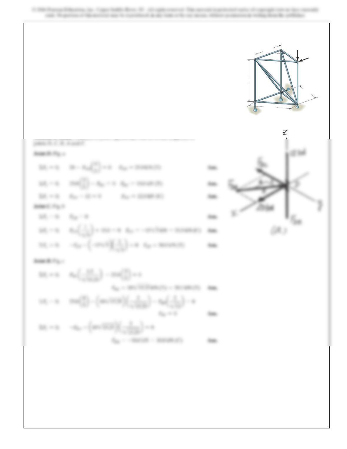
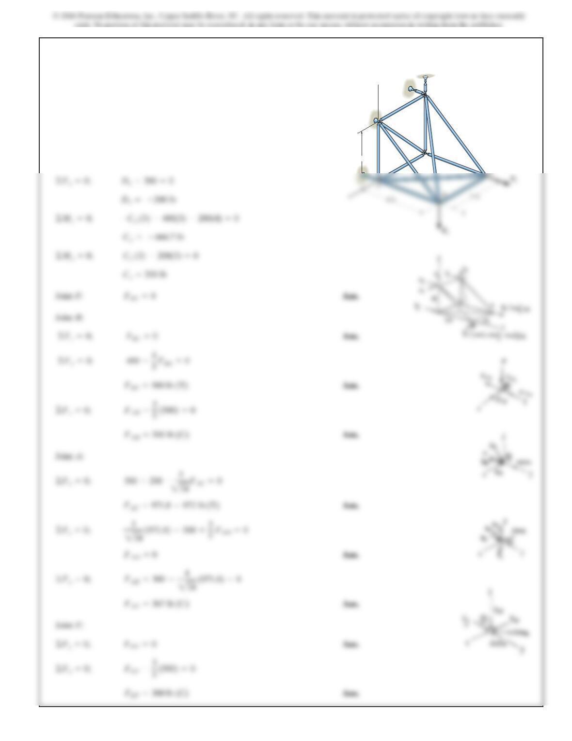
6–53.
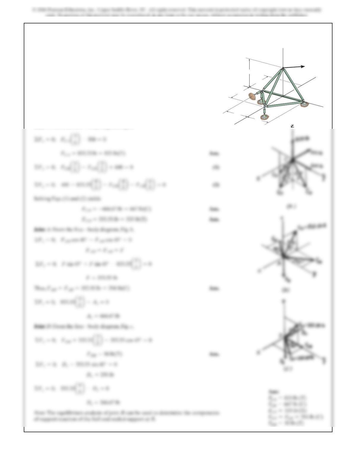
The space truss supports a force
. Determine the force in each member, and state if
the members are in tension or compression.
400k
6
lb
F=5–500i+600j+
A
B
C
D
x
y
z
F
8ft
6ft
6ft
6ft
6ft
SOLUTION
Method of Joints: In t
hi
s case,t
h
ere
i
s no nee
d
to compute t
h
e support react
i
ons.We
will begin by analyzing the equilibrium of joint C, and then that of joints Aand D.
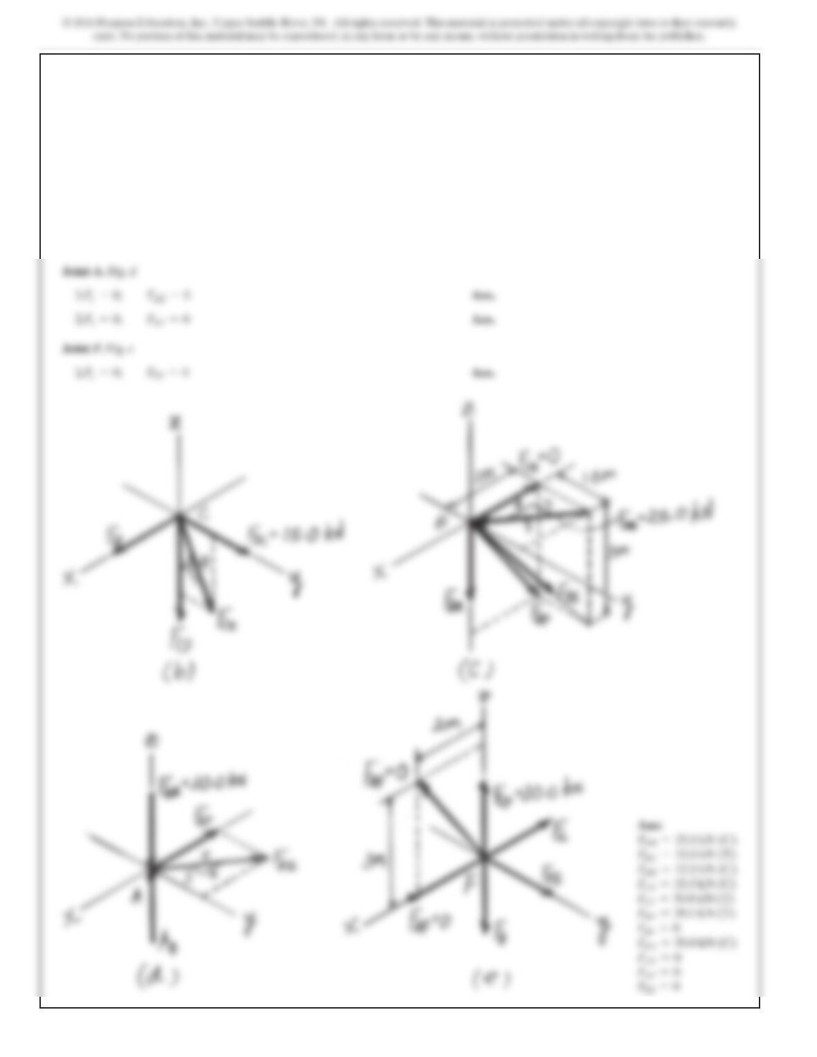
Joint C:From the free – body diagram, Fig. a,
Joint A:From the free – body diagram, Fig. b,
Joint D:From the free – body diagram, Fig. c,
©Fy=0; FDB +333.33a3
5b–353.55 cos 45° =0
©Fz=0; 833.33a4
5b–Az=0
©Fx=0; FAD cos 45° –FAB cos 45° =0
©Fx=0; FCA a3
5b–500 =0
542
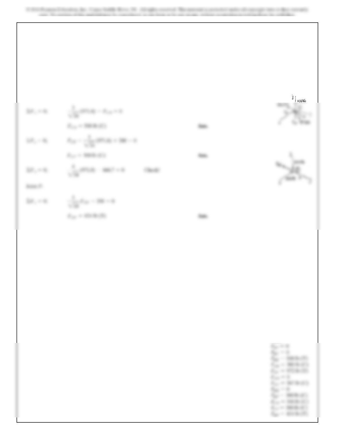
6–54.
SOLUTION
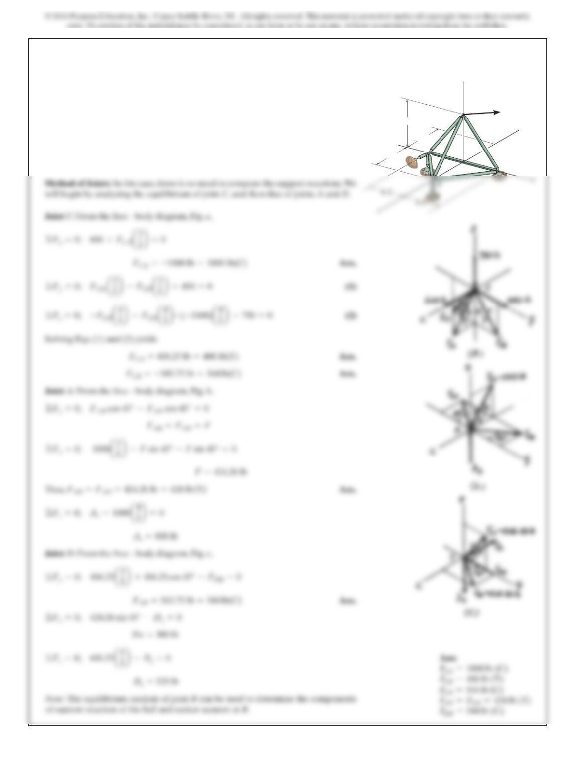
Method of Joints: In this case, there is no need to compute the support reactions.We
will begin by analyzing the equilibrium of joint C, and then that of joints Aand D.
Joint C:From the free – body diagram, Fig. a,
Solving Eqs. (1) and (2) yields
Joint A:From the free – body diagram, Fig. b,
Thus, Ans.
Joint D:From the free – body diagram, Fig. c,
©Fz=0; 406.25a4
©Fy=0; 406.25a3
5b+406.25 cos 45° –FDB =0
FAB =FAD =424.26 lb =424 lb (T)
©Fy=0; FAB cos 45° –FAD cos 45° =0
©Fx=0; 600 +FCA a3
5b=0
The space truss supports a force
. Determine the force in each member, and state if
the members are in tension or compression.
750k
6
lb
F=5600i+450j–
A
B
C
D
x
y
z
F
8ft
6ft
6ft
6ft
6ft
Ans:
543
SOLUTION
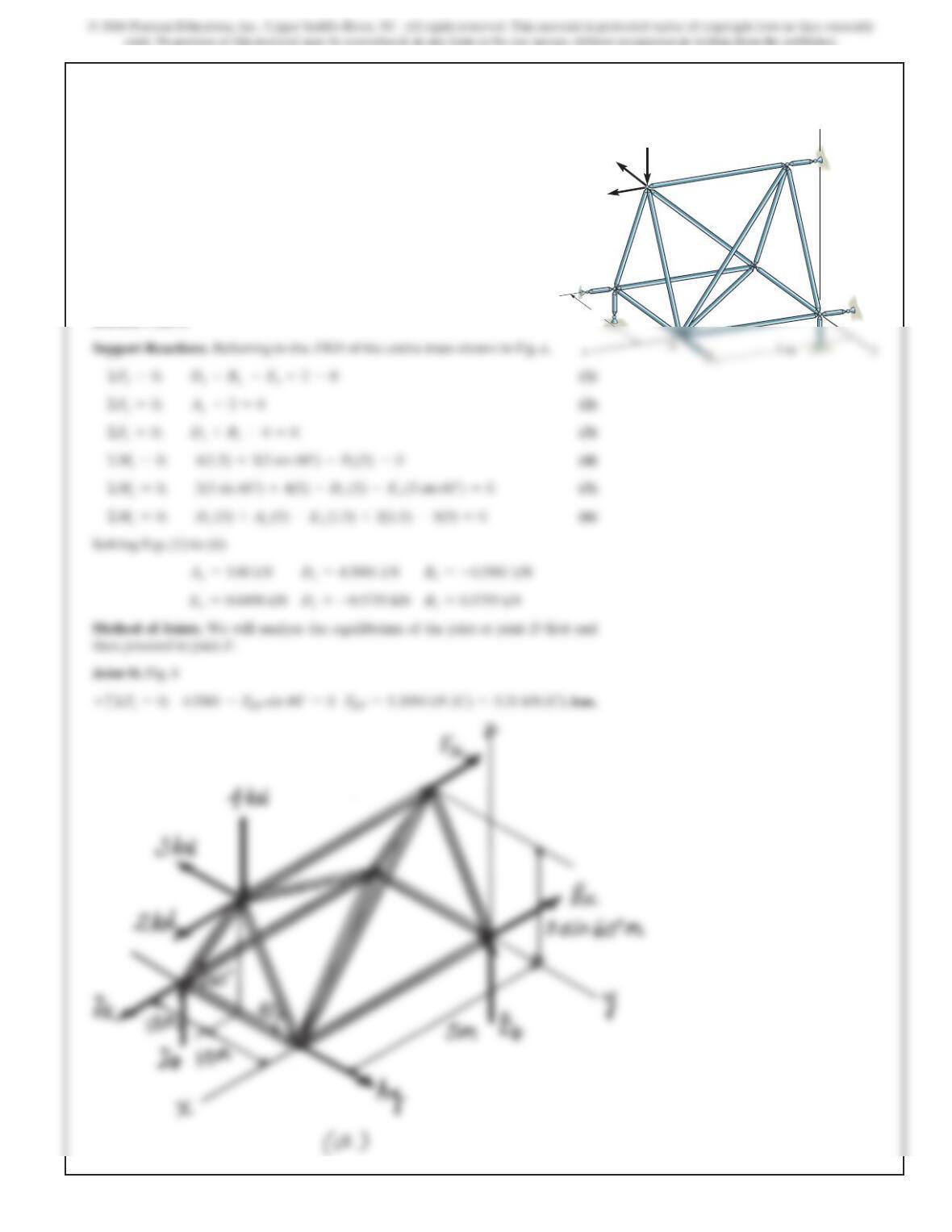
Support Reactions. Referring to the FBD of the entire truss shown in Fig. a,
ΣFx=0;
Dx–Bx –Ex+2=0
(1)
ΣF
y
=0;
A
y
–3=0
(2)
Dz+Bz–4=0
ΣMx=0;
ΣM
D
Solving Eqs. (1) to (6)
A
y
=3.00 kN
Dz=4.5981 kN
Bz=–0.5981 kN
Dx=–0.5755 kN
Method of Joints. We will analyse the equilibrium of the joint at joint D first and
then proceed to joint F.
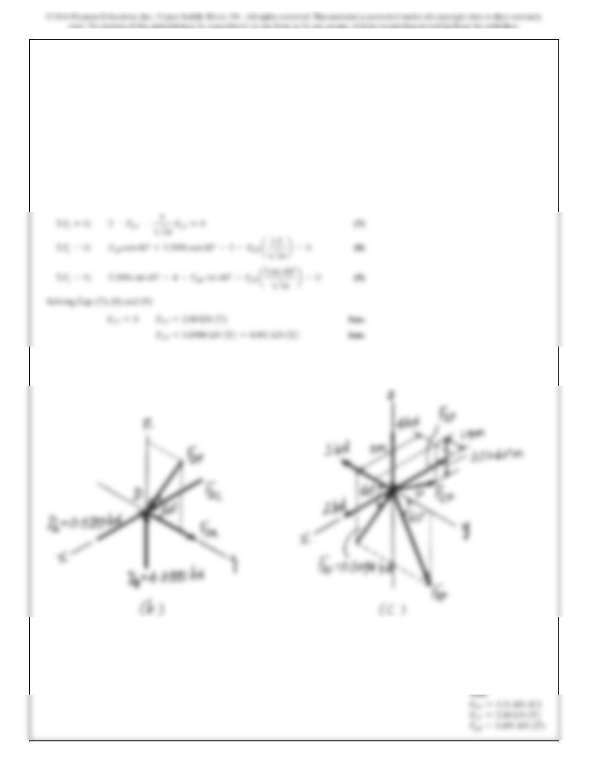
Joint D. Fig. b
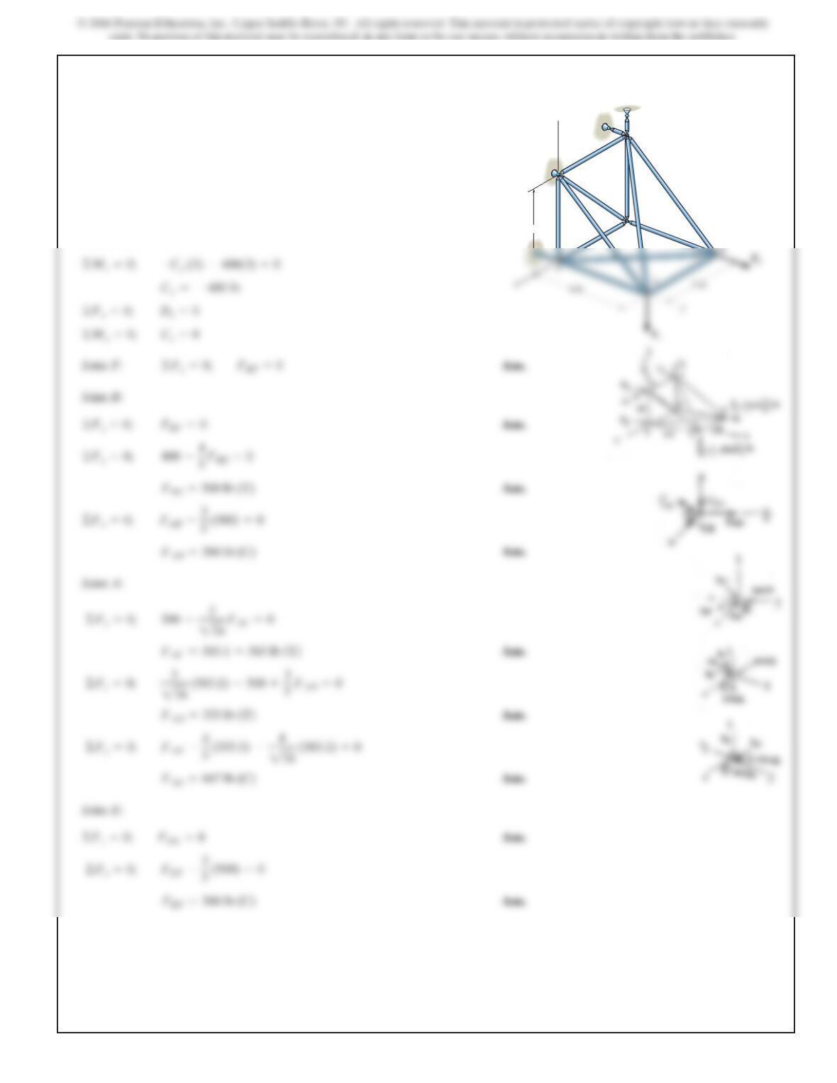
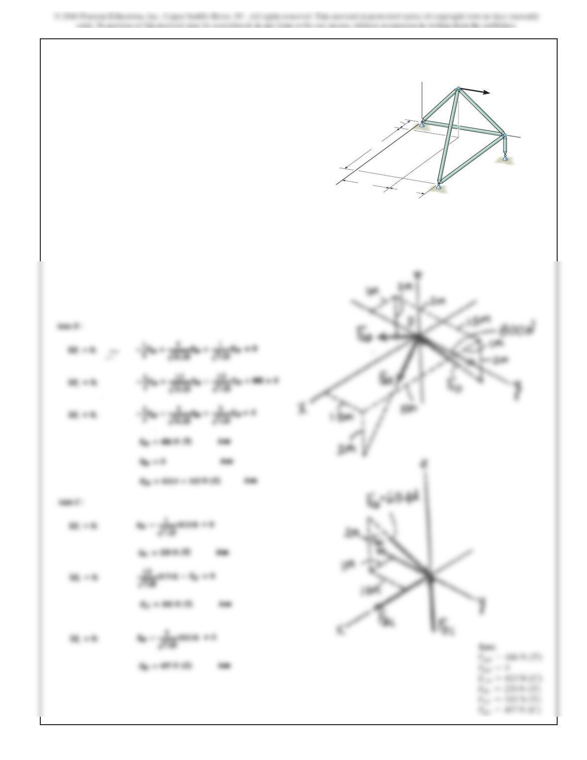
6–55.
Determine the force in members EF, AF, and DF of the
space truss and state if the members are in tension or
compression. The truss is supported by short links at A, B,
D, and E.
z
xy
3 m
3 m
4 kN
2 kN
3 kN
3 m
5 m
F
A
E
D
B
C
544
Joint F. Fig. c
ΣFx=0;
2 –FEF –
FCF =0 (7)
Solving Eqs. (7), (8) and (9)
6–55. Continued
Ans:
FDF =5.31 kN (C)
FEF =2.00 kN (T)
FAF =0.691 kN (T)
545
SOLUTION
Support Reactions. Not required
Method of Joints. Analysis of joint equilibrium will be in the sequence of
joints D,C, B, A and F.
Joint D. Fig. a
ΣFx=0;
20 –FDB
a4
5
b
=0
FDB =25.0 kN (T)
Ans.
ΣF
=0;
FDC =15.0 kN (T)
FDE =12.0 kN (C)
Joint C. Fig. b
ΣFx=0;
FCB =0
Ans.
ΣF
=0;
FCF =30.0 kN (T)
Joint B. Fig. c
ΣF
y
=0;
FBE
a
1.5
ΣFx=0;
–25.0
a
3
5
b
=0
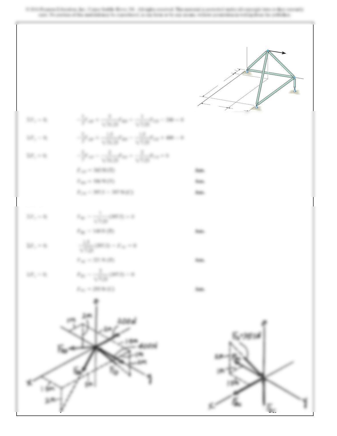
*6–56.
The space truss is used to support the forces at joints B and
D. Determine the force in each member and state if the
members are in tension or compression.
C
D
E
F
B
A
12 kN
20 kN
2 m
90
3 m
2.5 m
1.5 m
546
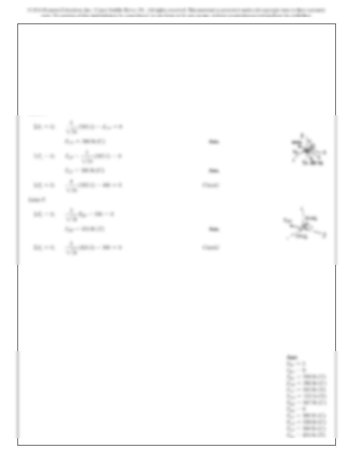
Joint A. Fig. d
Joint F. Fig. e
*6–56. Continued
Ans:
FDB =25.0 kN (C)
FDC =15.0 kN (T)
FDE =12.0 kN (C)
FCE =33.5 kN (C)
FCF =30.0 kN (T)
FBE =39.1 kN (T)
547
6–57.
The space truss is supported by a ball-and-socket joint at D
and
short links at Cand E. Determine the force in each
member
and state if the members are in tension or
compression.
Take and F
2
=5400j6lb.F
1
=5–500k6lb
SOLUTION
J
oint B:
J
oint A:
J
oint E:
C
y
=-400 lb
©M
z
=0; –C
y
(3) –400(3) =0
3ft
4ft
3ft
x
z
C
D
E
A
B
F
F
2
548
6–57. Continued
Joint C:
ΣFx=0;
3
234
(583.1) –FCD =0
4
234
ΣFx=0;
3
218
3
218
Ans:
FBF =0
FBC =0
549
6–58.
a
nd short links at Cand E. Determine the force in each
m
ember and state if the members are in tension or
c
ompression. Take and
F
550
J
o
i
6–58. Continued
Ans:
FBF =0
FBC =0
FAD =0
FDE =0
551
6–59.
Determine the force in each member of the space truss
and state if the members are in tension or compression. The
The truss is supported by ball-and-socket joints at A, B,
and E. Set . Hint: The support reaction at E
acts along member EC. Why?
F=5800j6 N
F
D
A
z
2 m
x
y
B
C
E
5 m
1 m
2 m 1.5 m
552
*6–60.
Determine the force in each member of the space truss and
state if the members are in tension or compression. The
truss is supported by ball-and-socket joints at A,B, and E.
Set . Hint: The support reaction at E
acts along member EC.Why?
F=5–200i+400j6N
F
D
A
z
2m
x
y
B
C
E
5m
1m
2m 1.5 m
SOLUTION
Joint D:
Joint C:
©Fz=0; FEC –2
27.25 (397.5) =0
©Fx=0; FBC –1
27.25 (397.5) =0
©Fx=0; –1
3FAD +5
231.25FBD +1
27.25FCD –200 =0
553
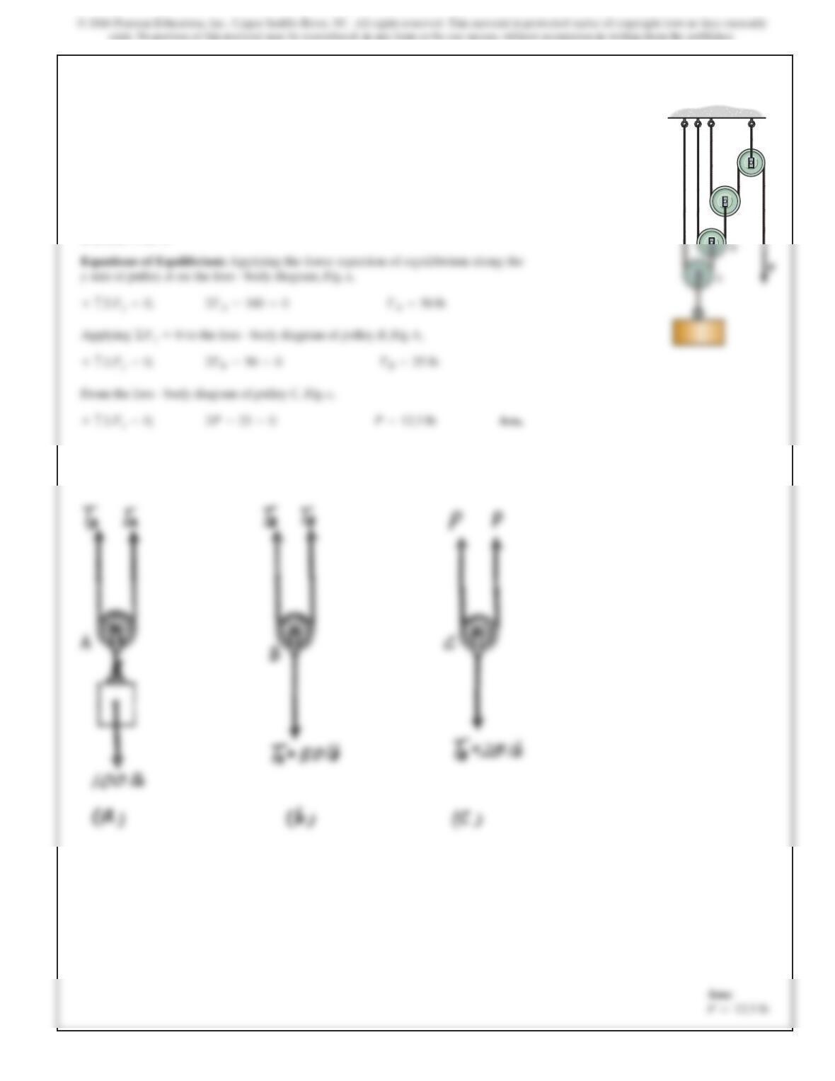
6–61.
Determine the force required to hold the
100-lb weight in equilibrium.
P
SOLUTION
Equations of Equilibrium: Applying the force equation of equilibrium along the
yaxis of pulley Aon the free – body diagram, Fig. a,
+c©Fy=0; 2TA–100 =0TA=50 lb
P
A
B
C
D
554
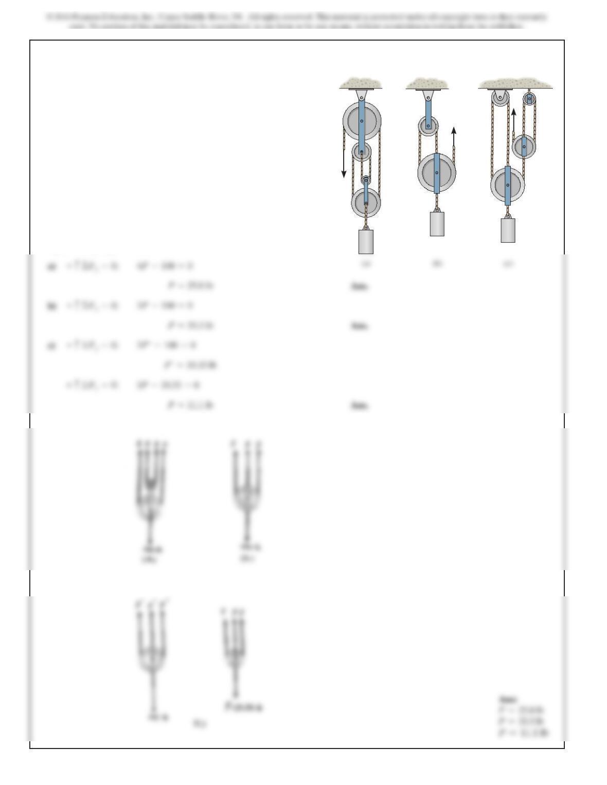
6–62.
P
(a) (b) (c)
P
P
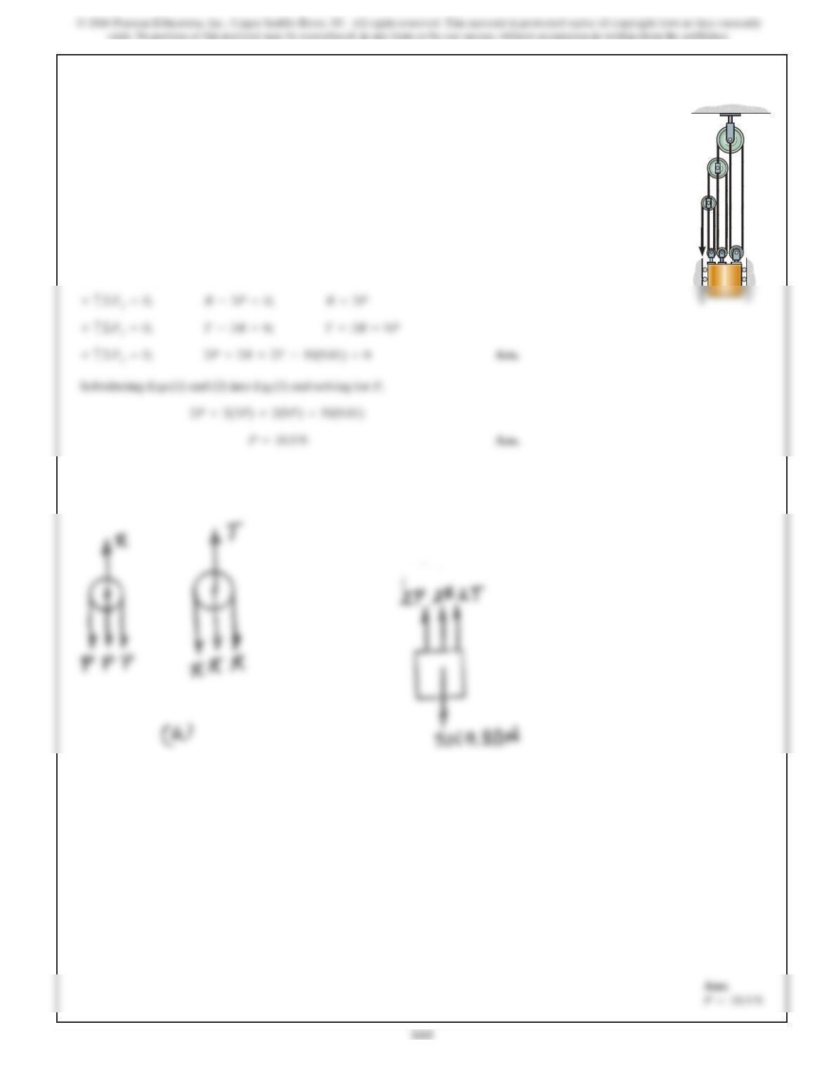
6–63.
Determine the force required to hold the 50-kg mass in
equilibrium.
P
SOLUTION
Equations of Equilibrium: Applying the force equation of equilibrium along the
yaxis of each pulley.
+c©Fy=0; R–3P=0; R=3P
P
A
B
C
Ans:
556
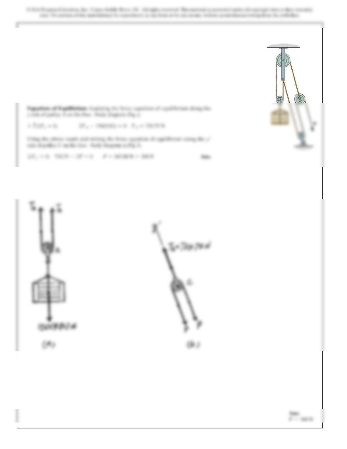
*6–64.
SOLUTION
Equations of Equilibrium: Applying the force equation of equilibrium along the
yaxis of pulley Aon the free – body diagram, Fig. a,
Determine the force required to hold the 150-kg crate
in equilibrium.
Ans:
557
SOLUTION
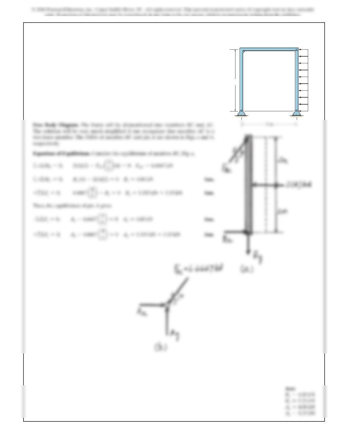
Free Body Diagram. The frame will be dismembered into members BC and AC.
Equations of Equilibrium. Consider the equilibrium of member BC, Fig. a,
a+
ΣMB=0;
2(4)(2) –FAC
a3
5b
(4) =0
FAC =6.6667 kN
Bx=4.00 kN
Then, the equilibrium of pin A gives
Ax=4.00 kN
6–65.
Determine the horizontal and vertical components of force
that pins A and B exert on the frame.
4 m
3 m
2 kN/m
A
C
B
Ans:
Bx=4.00 kN
Ax=4.00 kN
558
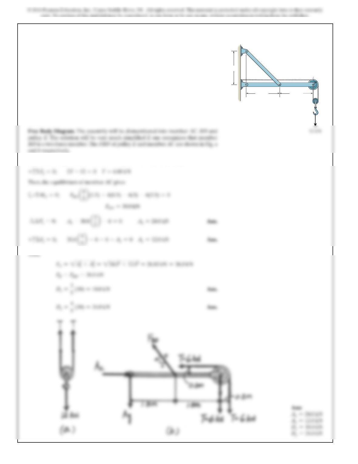
SOLUTION
Free Body Diagram. The assembly will be dismembered into member AC, BD and
Equations of Equilibrium. Consider the equilibrium of pulley E, Fig. a,
+
c
ΣF
y=
0;
2T – 12 =0
T=6.00 kN
Then, the equilibrium of member AC gives
S
+ Σ
F
x=
0; Ax–30.0
a3
5b
–6=0
Ax=24.0 kN
Ans.
+
c
ΣF
Thus,
FA=
2
Ax
2+Ay
2=
2
24.02+12.02=26.83 kN =26.8 kN
6–66.
Determine the horizontal and vertical components of force
at pins A and D.
1.5 m
D
AB
C
E
1.5 m
0.3 m
12 kN
2 m
559
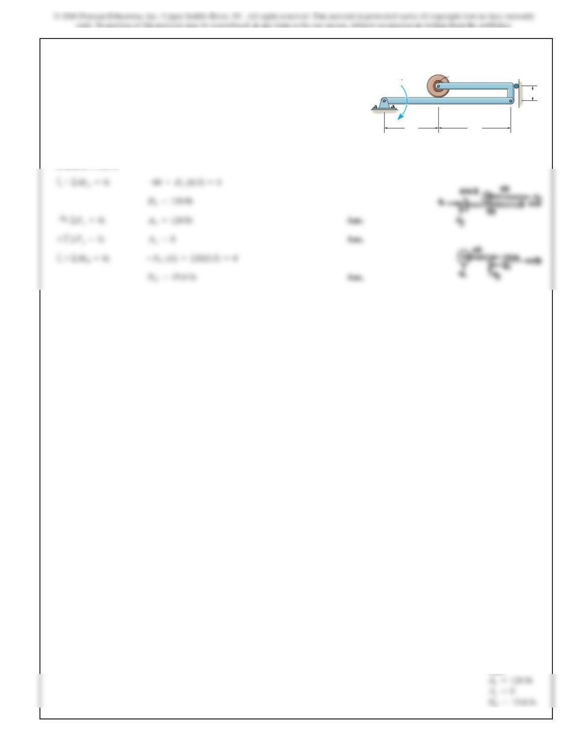
6–67.
Ans:
Ax=120
lb
NC=15.0
560
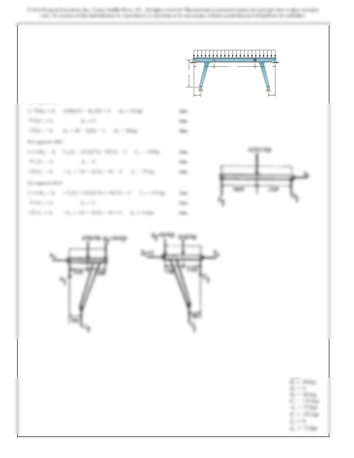
*6–68.
SOLUTION
For segment BD:
aAns.
For segment ABC:
aAns.
For segment DEF:
aAns.
+©Mg=0; –Fy(5) +2(15)(7.5) +30(15) =0Fy=135 kip
+©MA=0; Cy(5) –2(15)(7.5) –30(15) =0Cy=135kip
+©MD=0; 2(30)(15) –By(30) =0By=30 kip
The bridge frame consists of three segments which can be
considered pinned at A,D, and E, rocker supported at C
and F, and roller supported at B. Determine the horizontal
and vertical components of reaction at all these supports
due to the loading shown.
15 ft
20 ft
5ft5ft
15 ft
2kip/ft
30 ft
A
B
CF
D
E
Ans:
B
y
=30 kip
D