274
which can be rearranged and gives the second equation
122
22
111
0vvv
RRL
or
1222
0Lv Lv R v
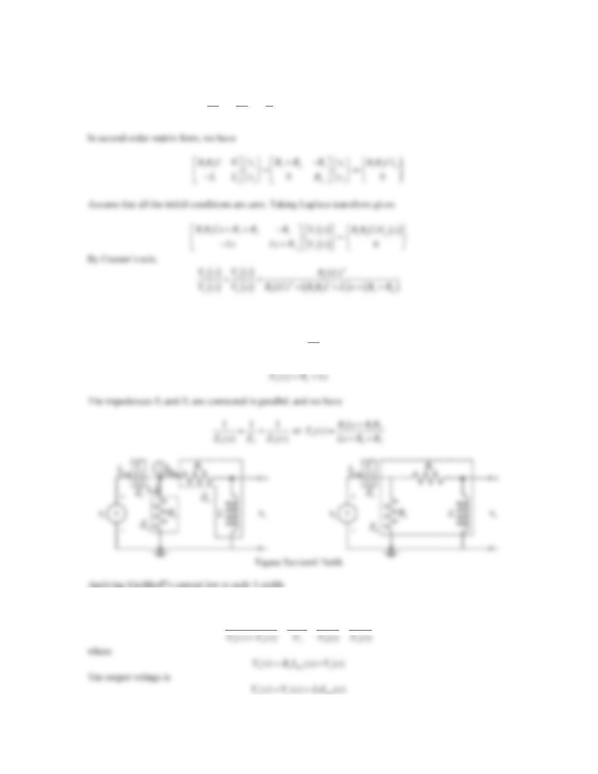
b. Replacing the passive elements with their impedance representations gives the circuit in the sdomain as shown
in the figure below, we have
1
1
()Zs Cs
21
ZR
CR1R2
() () ()Is I s I s
a11 1
() () () ()
Vs Vs Vs Vs
7. Consider the circuit shown in the Figure 6.77 (Review Problems, Problem 3).
a. Determine a suitable set of state variables and obtain the state-space representation.
b. Find the transfer function directly from the state-space form and compare with the result obtained in
Problem 3.
Solution
a. Refer to Figure 6.77 in Problem 3. Note that the circuit has three energy storage elements. However, the voltage
across the capacitor on the left side is same as the applied voltage vaand it is not independent. This implies that
two states are needed, and they are
1L 2 C
,xi x v
276
8. Repeat Problem 7 for the circuit shown in Figure 6.78 (Review Problems, Problem 4).
Solution
a. Refer to Figure 6.78 in Problem 4. Note that the circuit has two independent energy storage elements. This
implies that two states are needed, and they are
1C1 2C2
,xv xv
Their time derivatives are
277
b. The state-space form can be converted to a transfer function using
9. Repeat Problem 7 for the circuit shown in Figure 6.79 (Review Problems, Problem 5).
Solution
a. Refer to Figure 6.79 in Problem 5. Note that the circuit has two independent energy storage elements. This
implies that two states are needed, and they are
1C 2L
,xv xi
Their time derivatives are
C
1C
1
dv
xi
dt C
L
2L
1
di
xv
dt L
278
10. Repeat Problem 7 for the circuit shown in Figure 6.80 (Review Problems, Problem 6).
Solution
a. Refer to Figure 6.80 in Problem 6. Note that the circuit has two independent energy storage elements. This
implies that two states are needed, and they are
1C 2L
,xv xi
Their time derivatives are
279
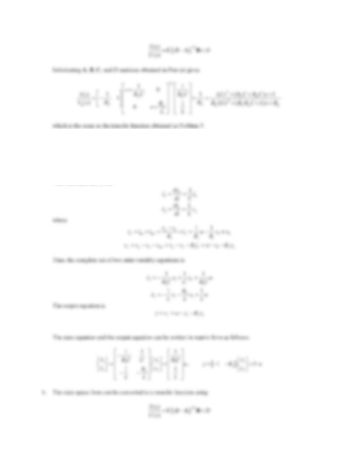
11. The op-amp circuit shown in Figure 6.81 is an active low-pass filter. Derive the input– output differential
equation relating the output voltage vo(t) and the input voltage vi(t). Find the transfer function Vo(s)/Vi(s)
directly from the input–output equation. Assume that all the initial conditions are zero.
Figure 6.81 Problem 11.
Solution
Note that the current drawn by the op-amp is very small, i.e., 0ii
||
. Applying Kirchhoff’s current law gives
R1 R2 C
iii
oo
i
12
()vv dvv
vv C
RR dt
where 0vv
|
. Thus, we have
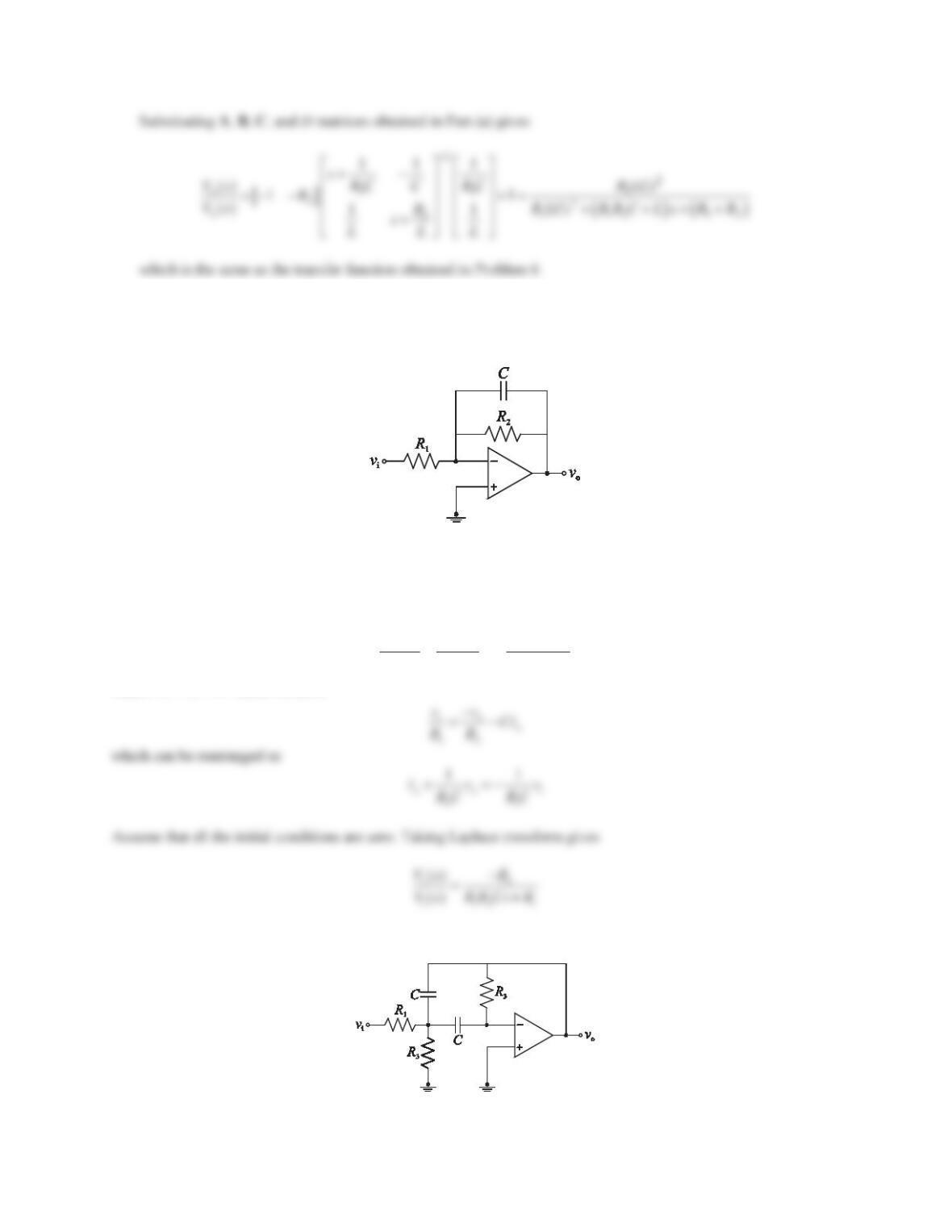
12. Repeat Problem 11 for the op-amp circuit shown in Figure 6.82, which represents an active band-pass filter.
Figure 6.82 Problem 12.
280
Solution
Note that the current drawn by the op-amp is very small, i.e., 0ii
||
. Applying Kirchhoff’s current law to node 1
gives
R1 R2 C1 C2
iiii
1o
i1 1 1
12
()
()
dv v
vv v dvv
CC
R R dt dt
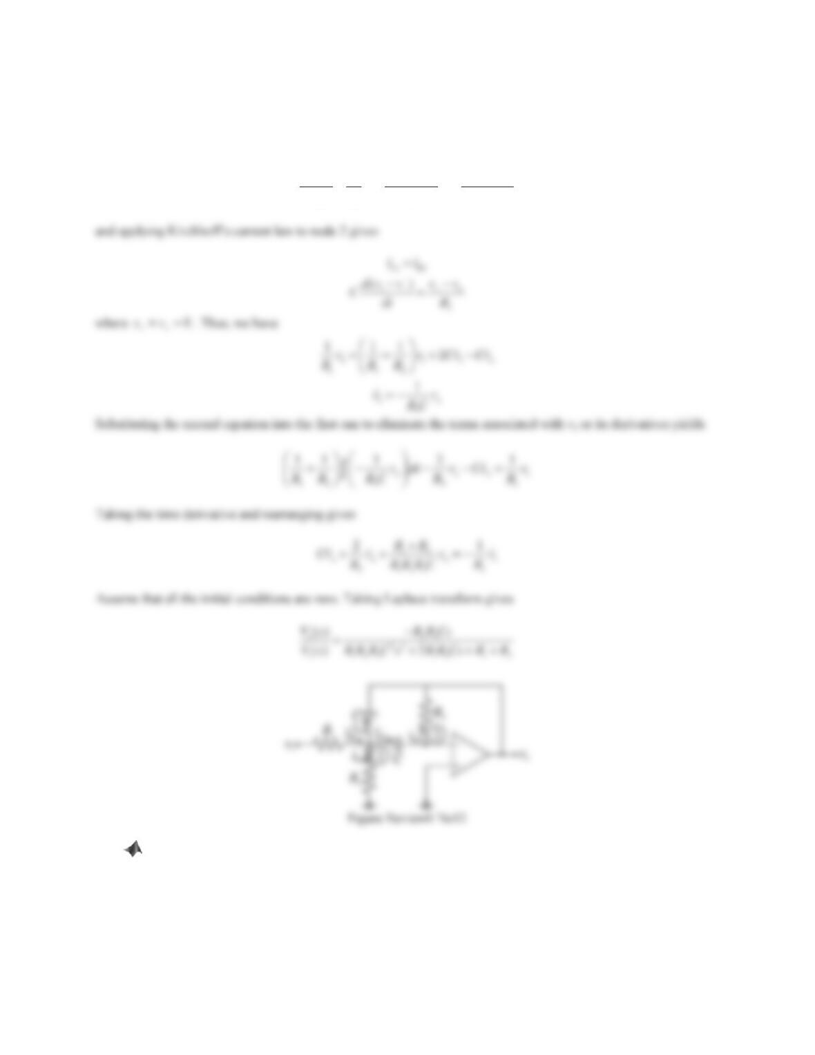
13. Consider the RLC circuit shown in Figure 6.30 (Problem Set 6.2, Problem 15), where R1= 100 :,L= 20
H, R2= 400 :, and C= 1/120 F. The circuit is driven by a 100 V DC voltage source.
a. Build a Simscape model of the physical system and find the output voltage vo(t).
b. Build a Simulink model of the system based on the state-space form and find the output voltage vo(t).
Solution
a. Simscape block diagram:
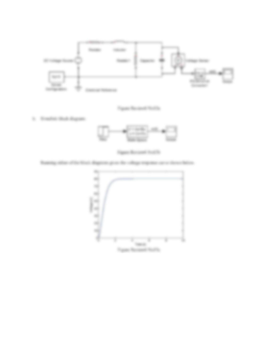
281
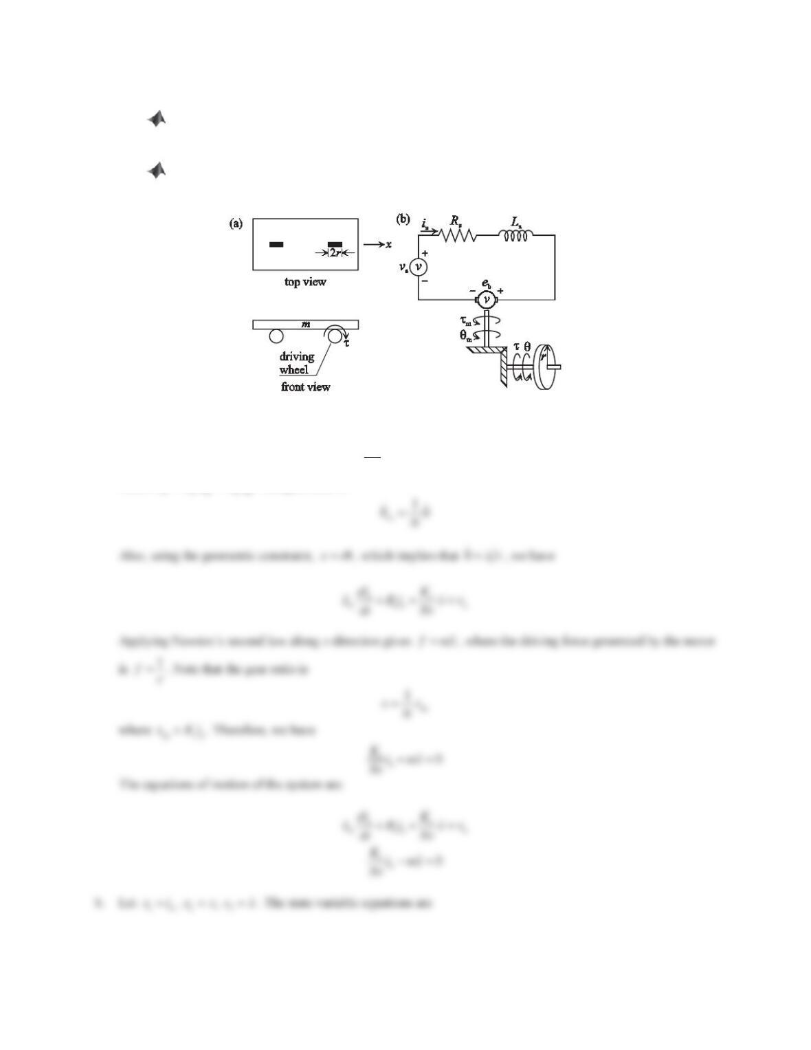
14. Consider the DC motor driven wheeled mobile robot shown in Figure 6.83a, where mis the mass of the
wheeled mobile robot, ris the radius of the driving wheel, and
W
is the torque delivered to the wheeled mobile
robot by the DC motor. For simplicity, the motion is restricted to one spatial dimension. Figure 6.83b shows the
simplified drive system, including the equivalent electrical circuit of the DC motor, the rotor of the DC motor,
the gears, and the driving wheel. The motor parameter values are armature inductance La= 0.001 H, resistance
Ra= 2.6 :back emf constant Ke= 0.008 Vs/rad, and torque constant Kt= 0.008 Nm/A. The mass moment of
inertia of the motor can be negligible. The gear ratio N=T/Tm=Wm/W= 1/3.7, where Tm,T,Wm, and Ware torque
and angular velocity before and after gears. The wheel and axle mechanism converts the rotational motion to
translation, and the wheel radius r= 0.00635 m. The mass of the cart m= 0.455 kg.
a. Derive the equations of motion of the system.
b. Choose the armature current ia, the robot displacement xand the robot velocity x
as state variables and
find the state-space form of the system.
282
c. Find the transfer function X(s)/Va(s). Assume that all initial conditions are zero.
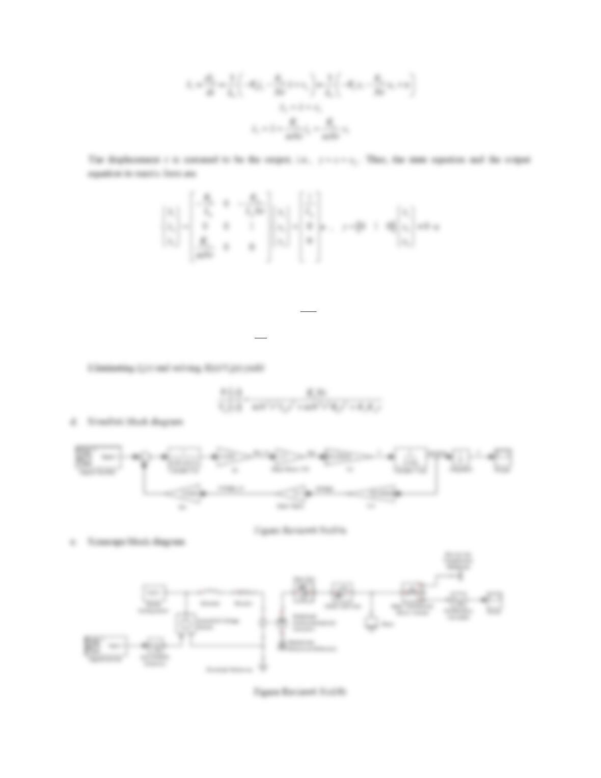
d. Following Figure 6.45, build a Simulink block diagram using the differential equations obtained in
Part (a) and find the displacement output x(t) when the voltage applied to the DC motor is an impulse
function, va(t 9IRUW2 s.
e. Build a Simscape model of the wheeled mobile robot and find the displacement output x(t) when the
voltage applied to the DC motor is an impulse function, va(t 9IRUW2 s.
Figure 6.83 Problem 14.
Solution
a. Applying Kirchhoff’s voltage law gives
a
aaaba
di
LRiev
dt
where
bemem
ȦșeK K
. The gear ratio is
283
c. Assuming all the initial conditions to be zero and taking the Laplace transform for the equations in Part (a), we
have
e
aaa a
( ) () () ()
Ks
Ls R I s X s V s
Nr
2
t
a() () 0
KIs msXs
Nr
284
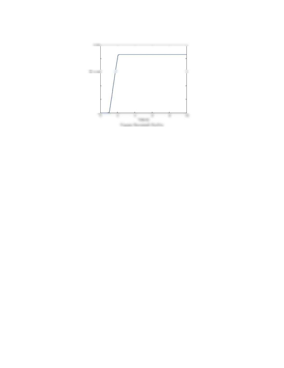
Running either of the block diagrams gives the displacement response as shown in figure below.
0.05
0.1
0.2
Displacement (m)