481
SOLUTION
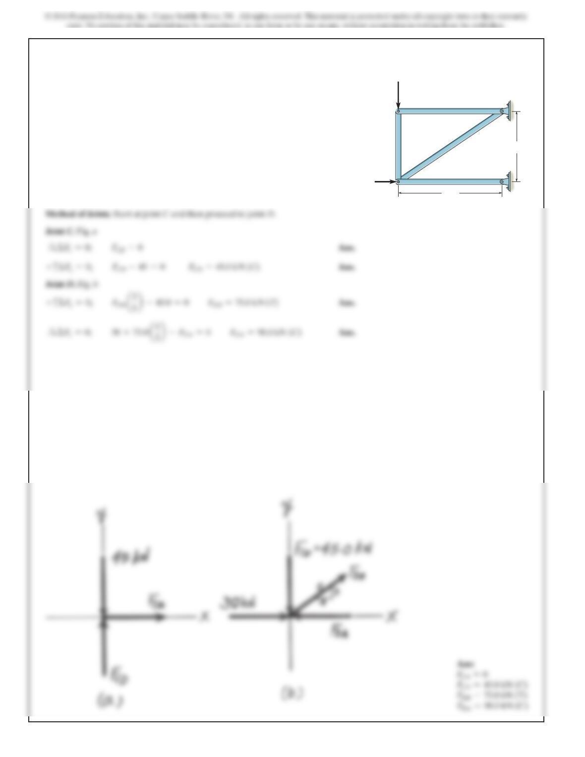
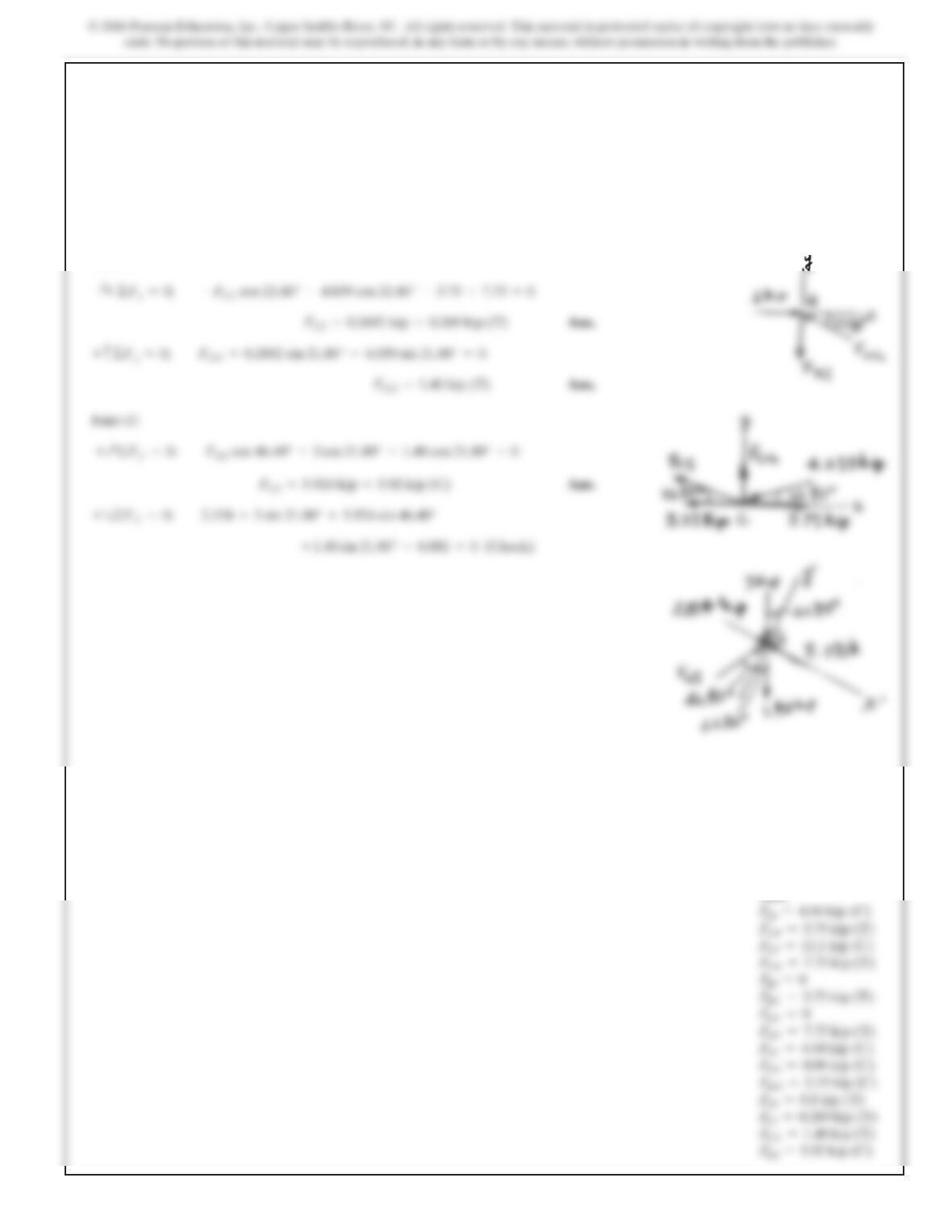
Method of Joints. Start at joint C and then proceed to join D.
Joint C. Fig. a
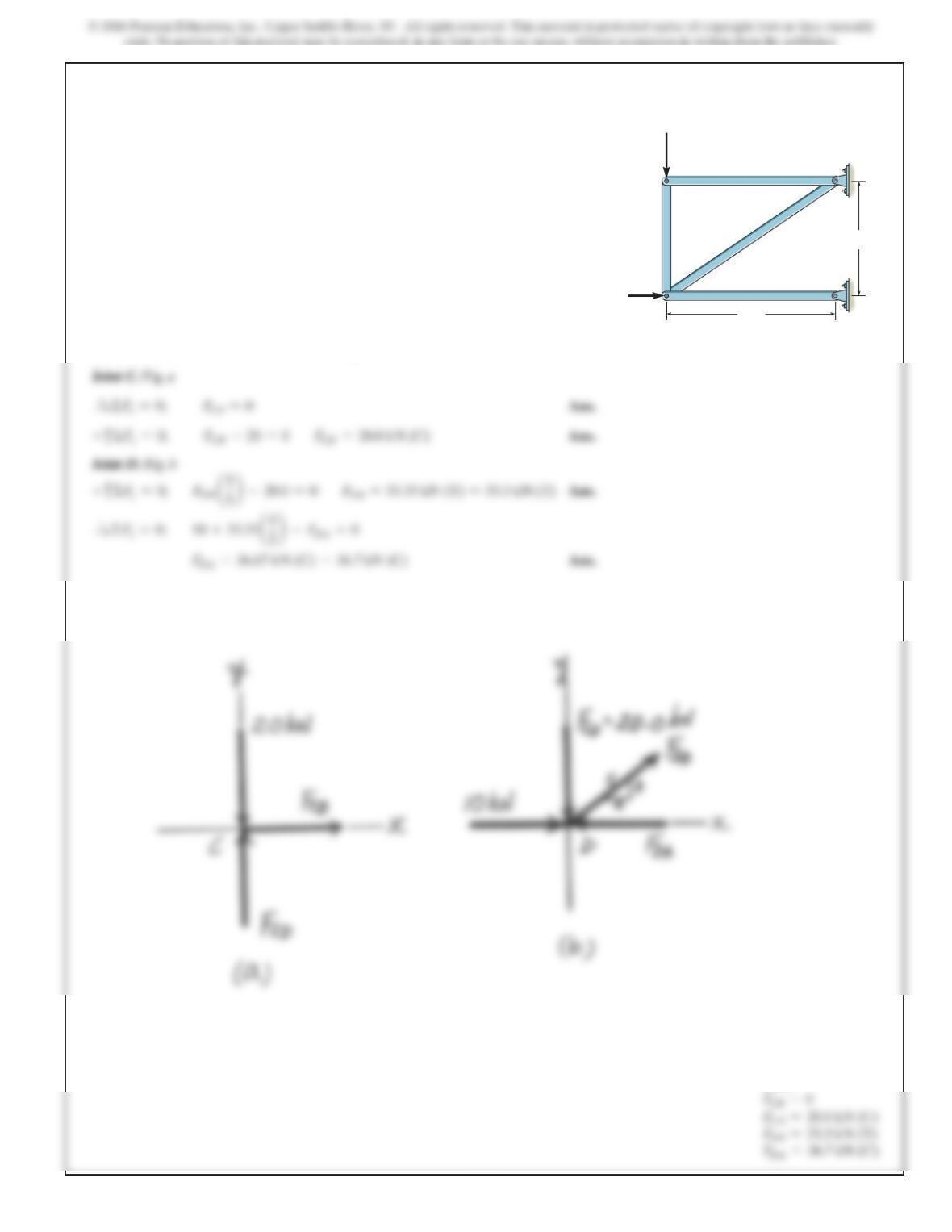
6–1.
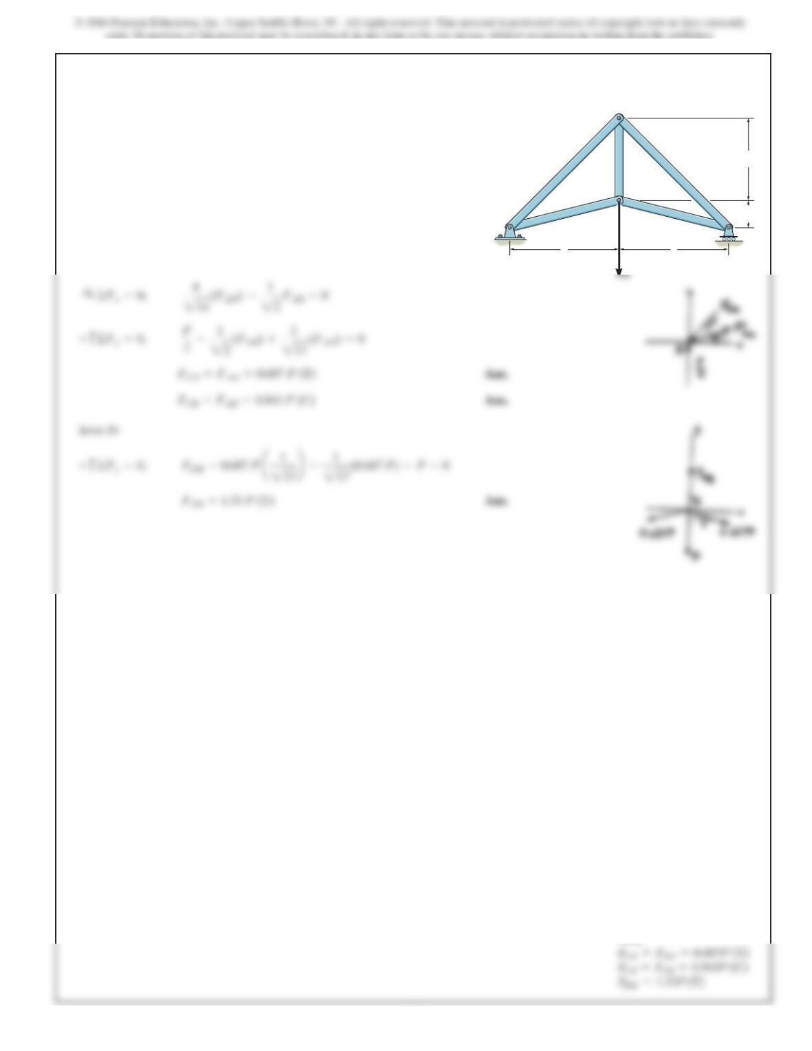
Determine the force in each member of the truss and state
if the members are in tension or compression. Set
P1 = 20 kN, P2 = 10 kN.
CB
A
D
1.5 m
2 m
P1
P2
Ans:
482
SOLUTION
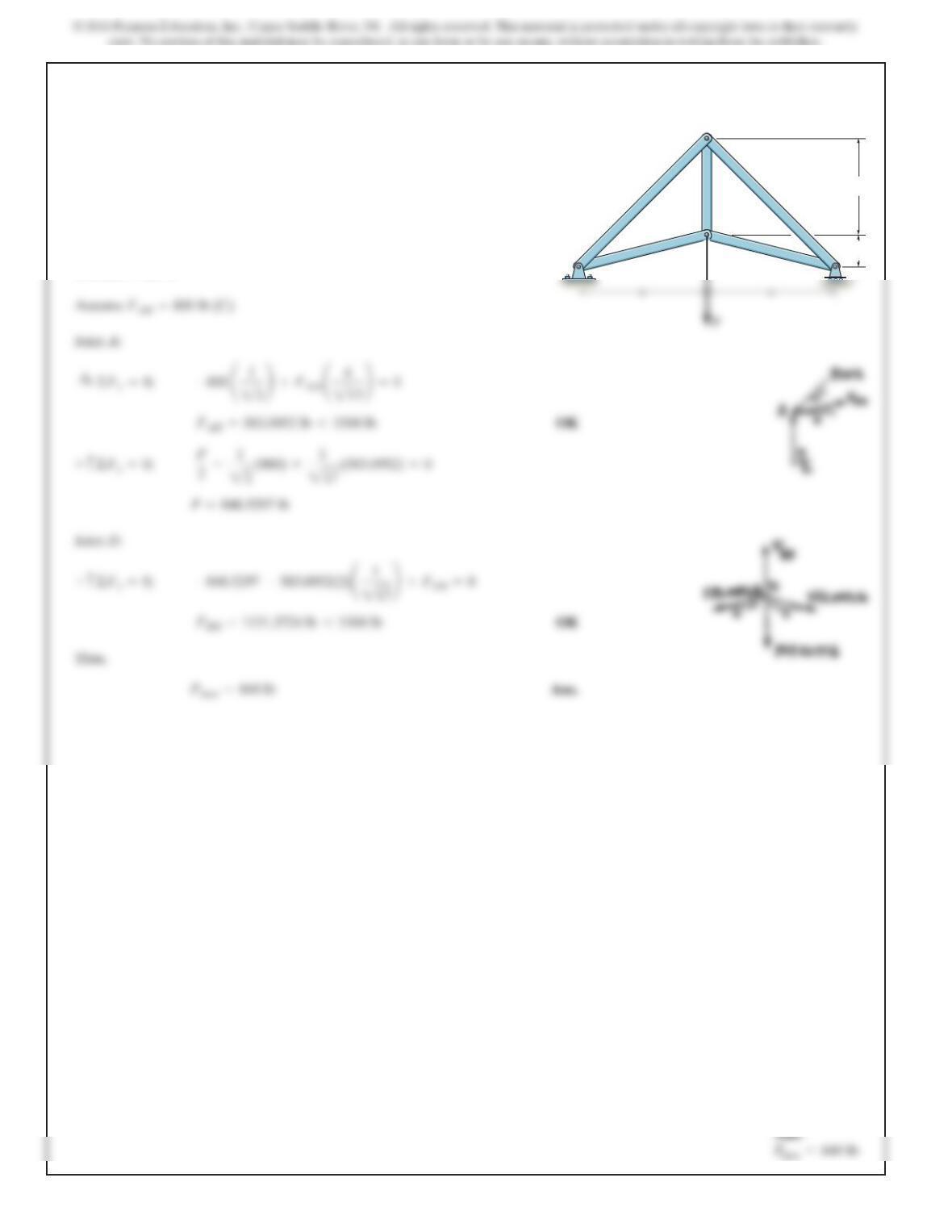
6–2.
Determine the force in each member of the truss and state
if the members are in tension or compression. Set
P1 = 45 kN, P2 = 30 kN.
CB
A
D
1.5 m
2 m
P1
P2
Ans:
FCB =0
483
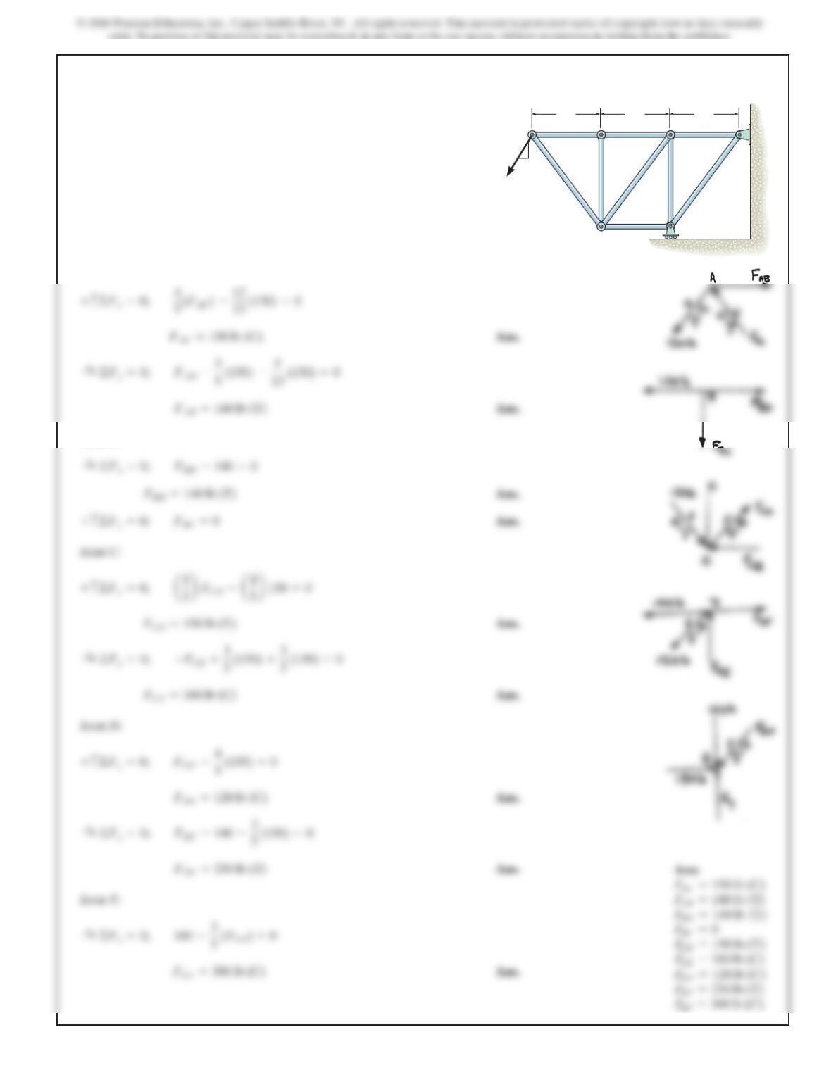
6–3.
SOLUTION
Joint A:
Joint B:
Joint D:
+c©Fy=0; 4
5(FAC)–12
13 (130) =0
Determine the force in each member of the truss. State if
the members are in tension or compression.
3ft3ft3ft
12
5
13
130 lb
AB
C
E
D
F
4 ft 4 ft
484
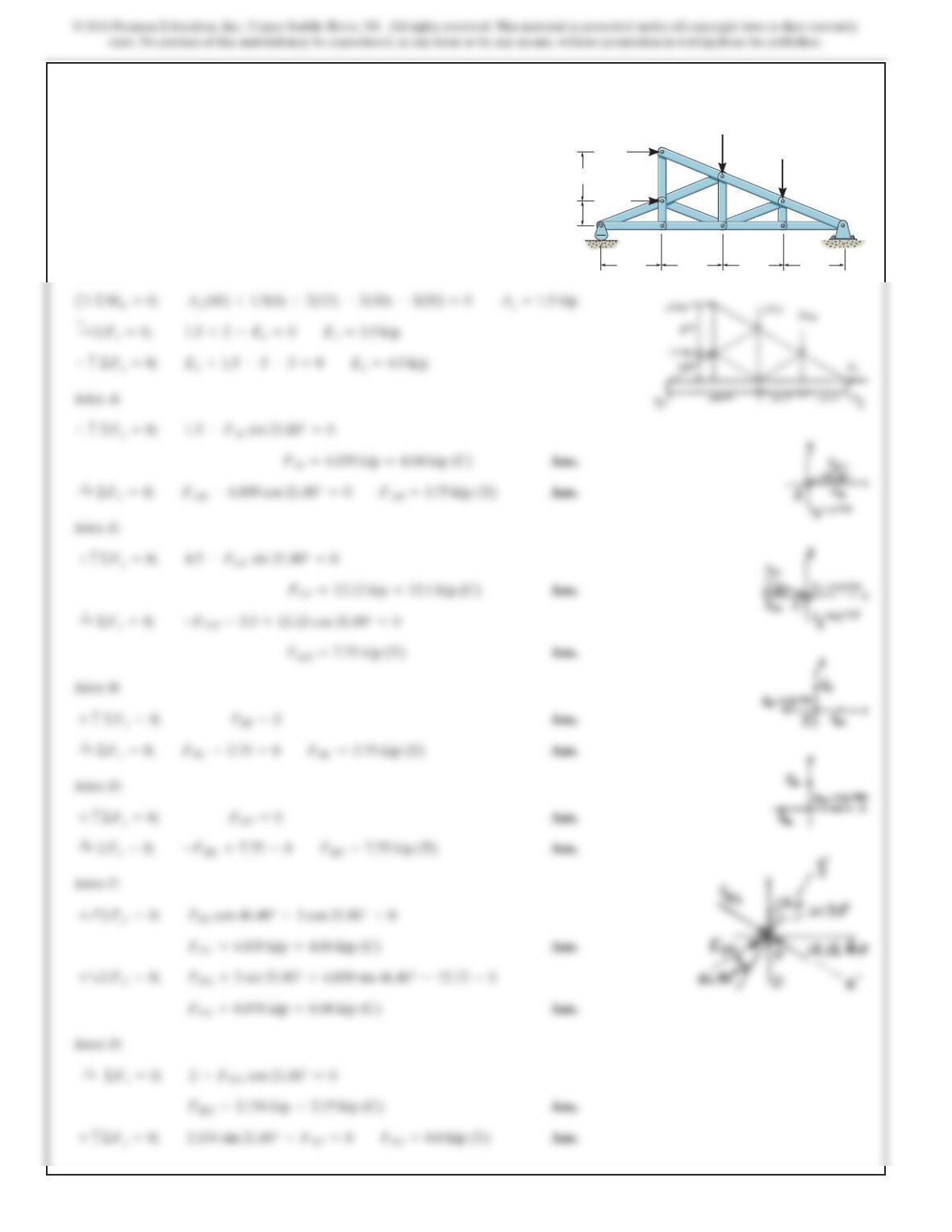
*6–4.
SOLUTION
c
Joint A:
Joint B:
Joint F:
Joint H:
:
+©Fx=0; –FED –3.5 +12.12 cos 21.80° =0
+c©Fy=0; 1.5 –FAl sin 21.80° =0
+©ME=0;
Ay(40) +1.5(4) +2(12) –3(10) –3(20) =0Ay=1.5 kip
Determ
i
ne t
h
e force
i
n eac
h
mem
b
er of t
h
e truss an
d
state
if the members are in tension or compression. 2kip
1.5 kip
4ft
10 ft 10 ft 10 ft
3kip
3kip
10 ft
AB
I
H
G
F
CD
E
8ft
485
*6–4. Continued
Joint C:
J
oint G:
:
+©Fx=0; –FCI cos 21.80° –4.039 cos 21.80° –3.75 +7.75 =0
Ans:
FAl =4.04 kip (C)
FAB =3.75 kip (T)
FEF =12.1 kip (C)
FED =7.75 kip (T)
FBC =3.75 kip (T)
FDC =7.75 kip (T)
FFC =4.04 kip (C)
FFG =8.08 kip (C)
486
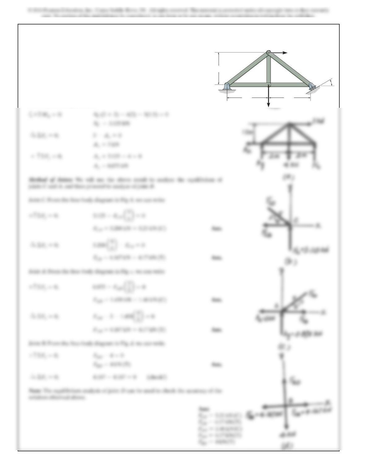
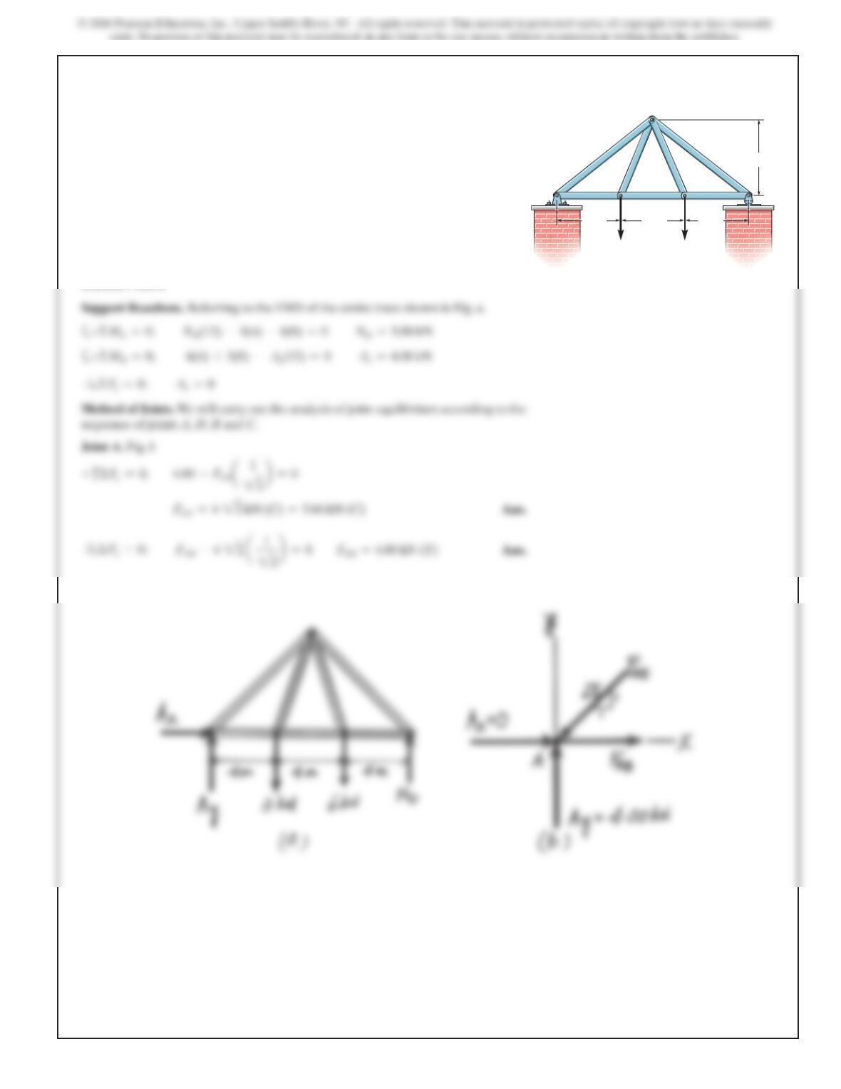
6–5.
Determine the force in each member of the truss, and state
if the members are in tension or compression. Set .
SOLUTION
Support Reactions: Applying the equations of equilibrium to the free-body diagram
of the entire truss,Fig.a, we have
a
Method of Joints: We will use the above result to analyze the equilibrium of
joints Cand A, and then proceed to analyze of joint B.
Joint A:From the free-body diagram in Fig. c, we can write
0.875 –F
AD a3
y=0;
N
C =3.125 kN
N
C (2 +2) –4(2) –3(1.5) =0+©MA=0;
u=0°
AC
B
D
2 m
4 kN
3 kN
2 m
1.5 m
u
487
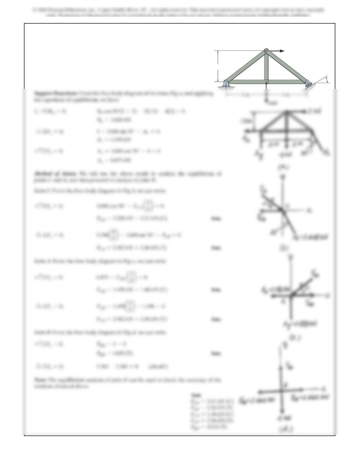
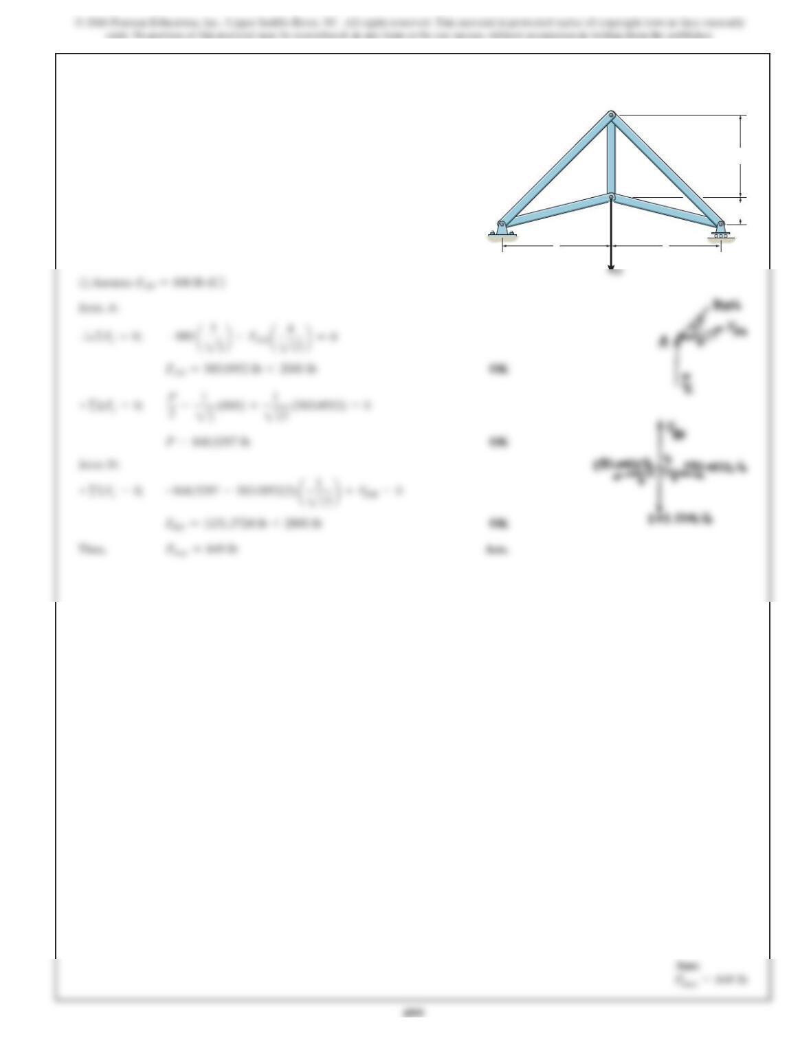
6–6.
Determine the force in each member of the truss, and state
if the members are in tension or compression. Set .
SOLUTION
Support Reactions: From the free-body diagram of the truss,Fig. a, and applying
the equations of equilibrium, we have
Method of Joints: We will use the above result to analyze the equilibrium of
joints Cand A, and then proceed to analyze of joint B.
Joint C:From the free-body diagram in Fig. b, we can write
Joint A:From the free-body diagram in Fig. c, we can write
Joint B:From the free-body diagram in Fig. d, we can write
Note: The equilibrium analysis of joint Dcan be used to check the accuracy of the
solution obtained above.
u=30°
AC
B
D
2 m
4 kN
3 kN
2 m
1.5 m
u
488
6–7.
489
6–7. Continued
Ans:
FDE =16.3
kN (C)
FDC =8.40
kN (T)
FEA =8.85
FEC =6.20
490
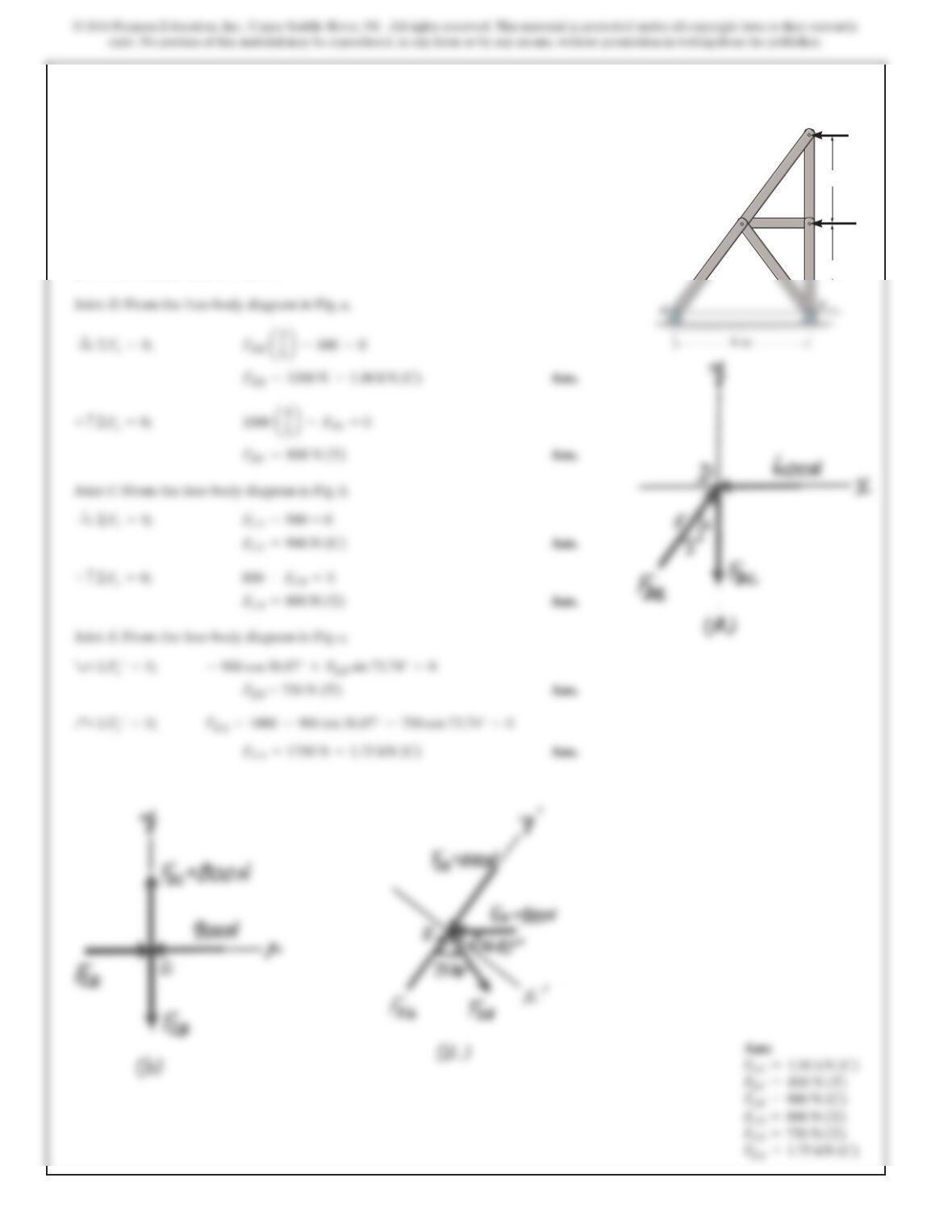
*6–8.
Determine the force in each member of the truss, and state
if the members are in tension or compression.
SOLUTION
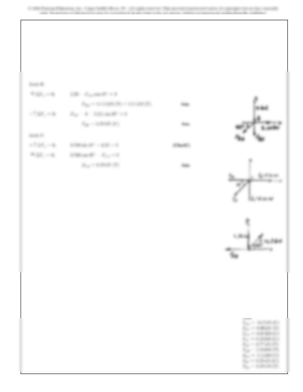
Method of Joints: We will begin by analyzing the equilibrium of joint D, and then
proceed to analyze joints Cand E.
Joint D:From the free-body diagram in Fig. a,
Joint C:From the free-body diagram in Fig. b,
Joint E:From the free-body diagram in Fig. c,
F
CE –900 = 0©F
x=0;
:
+
B
E
D
A
C
600 N
900 N
4 m
4 m
Ans:
FDE =1.00 kN (C)
FDC =800 N (T)
FCE =900 N (C)
FCB =800 N (T)
FEB =750 N (T)
FEA =1.75 kN (C)
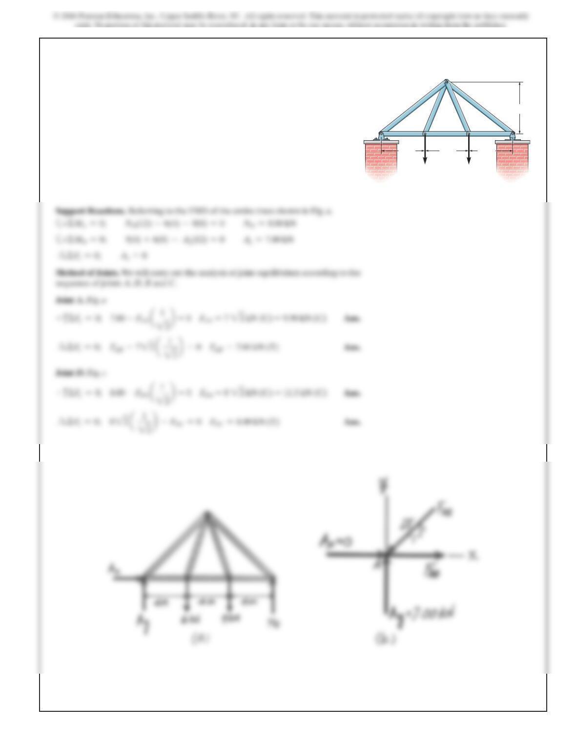
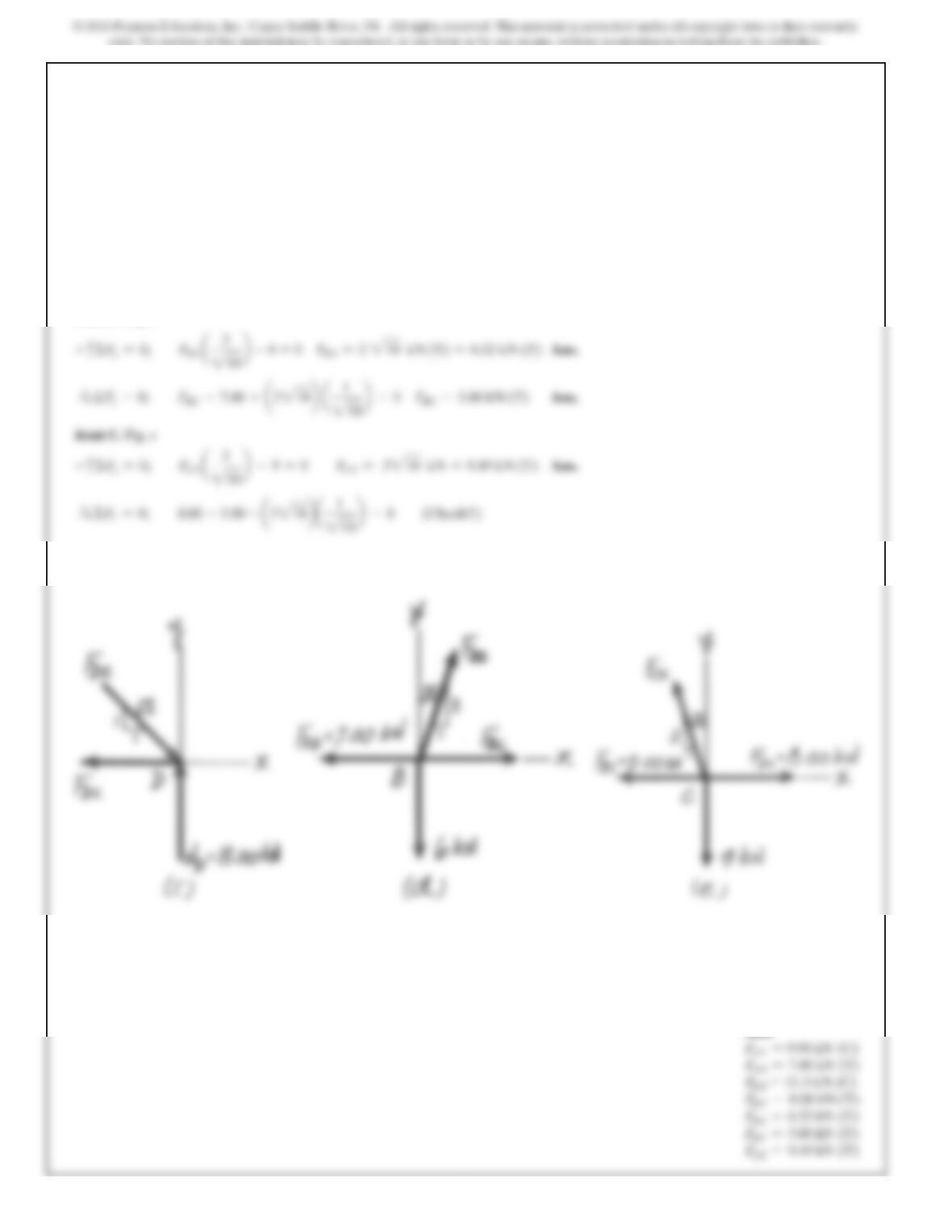
491
SOLUTION
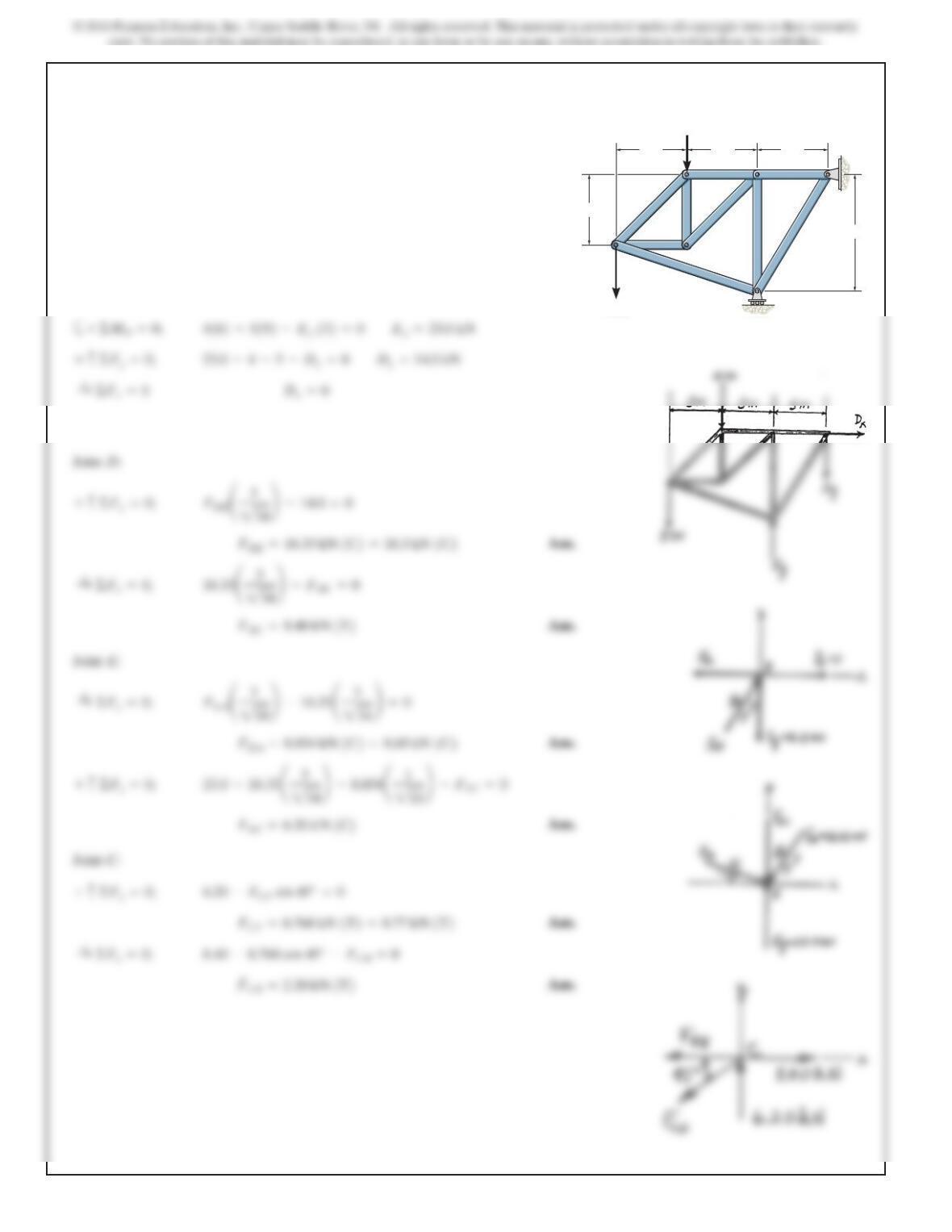
Support Reactions. Referring to the FBD of the entire truss shown in Fig. a,
6(4) +3(8) – A
x=
Method of Joints. We will carry out the analysis of joint equilibrium according to the
sequence of joints A, D, B and C.
Joint A. Fig. b
+
c
ΣF
y
=0;
4.00 –FAE
a
=0
6–9.
Determine the force in each member of the truss and state
if the members are in tension or compression. Set
P1 = 3 kN, P2 = 6 kN.
AD
E
B C
P1P2
4 m4 m4 m
6 m
492
6–9. Continued
+
c
Σ
FDC =5.00 kN (T)
Joint B. Fig. d
+
c
Σ
Fy=0; FBE
a
3
210 b
–3=0 F
BE =2
10 kN (T)
=
3.16 kN (T) Ans.
FBC =3.00 kN (T)
a
3
210 b
Ans:
FAE =5.66 kN (C)
FAB =4.00 kN (T)
493
SOLUTION
Support Reactions. Referring to the FBD of the entire truss shown in Fig. a,
a+
ΣMA=0;
ND(12) –6(4) –9(8) =0
ND=8.00 kN
9(4) +6(8) – A
Method of Joints. We will carry out the analysis of joint equilibrium according to the
sequence of joints A, D, B and C.
Joint A. Fig. a
+
c
ΣF
2
Joint D. Fig. c
+
c
ΣF
y=
0;
8.00 –FDE
=0 F
DE =
8
2
2 kN (C)
=
11.3 kN (C) Ans.
6–10.
Determine the force in each member of the truss and state
if the members are in tension or compression. Set P1 = 6 kN,
P2 = 9 kN.
AD
E
B C
P1P2
4 m4 m4 m
6 m
494
Joint B. Fig. d
+
c
ΣF
y
=0;
FBE
a
3
210 b
–6=0 F
BE =
2
2
10 kN (T)
=
6.32 kN (T) Ans.
Joint C. Fig. e
+
c
Σ
Fy=0; FCE
210 b
–9=0 F
CE =
3
2
10 kN
=
9.49 kN (T) Ans.
6–10. Continued
Ans:
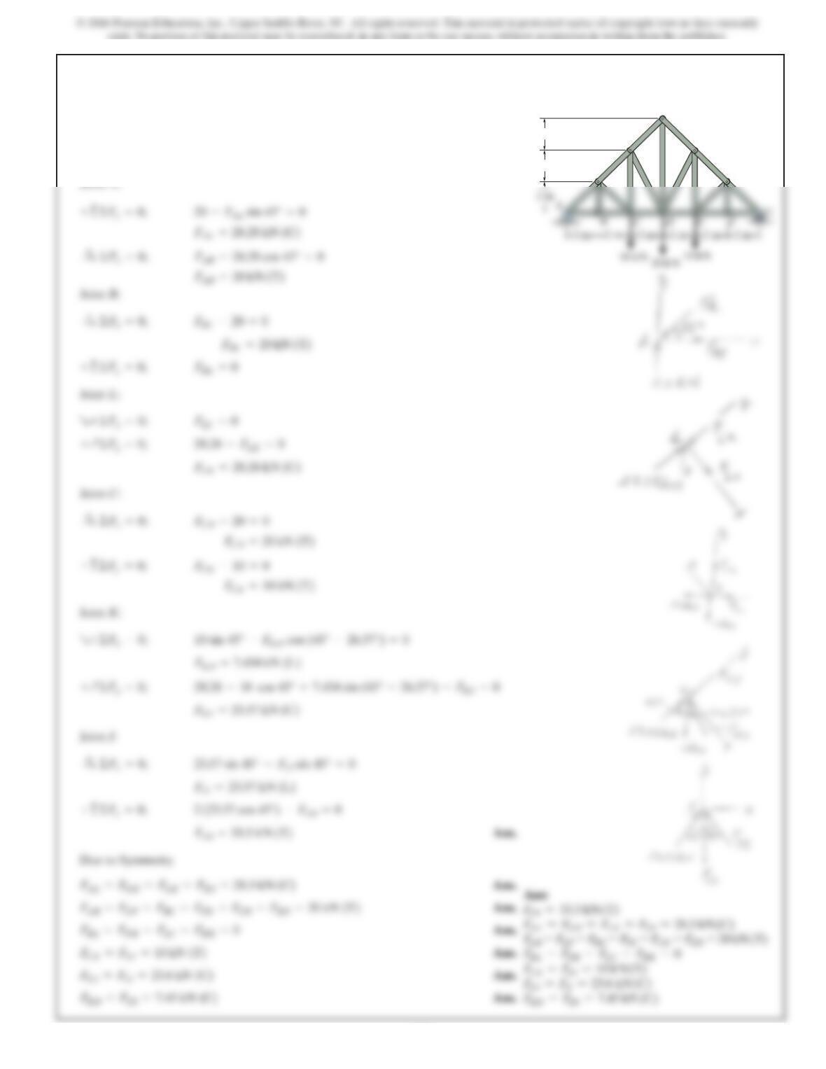
495
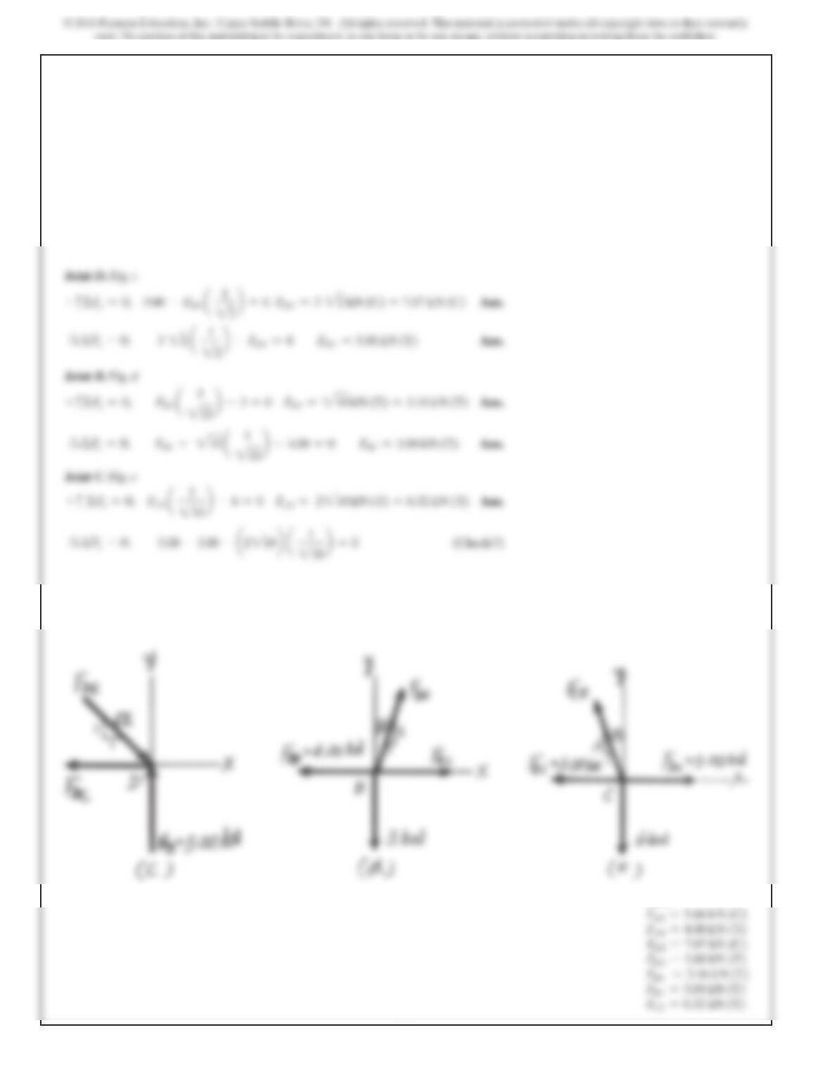
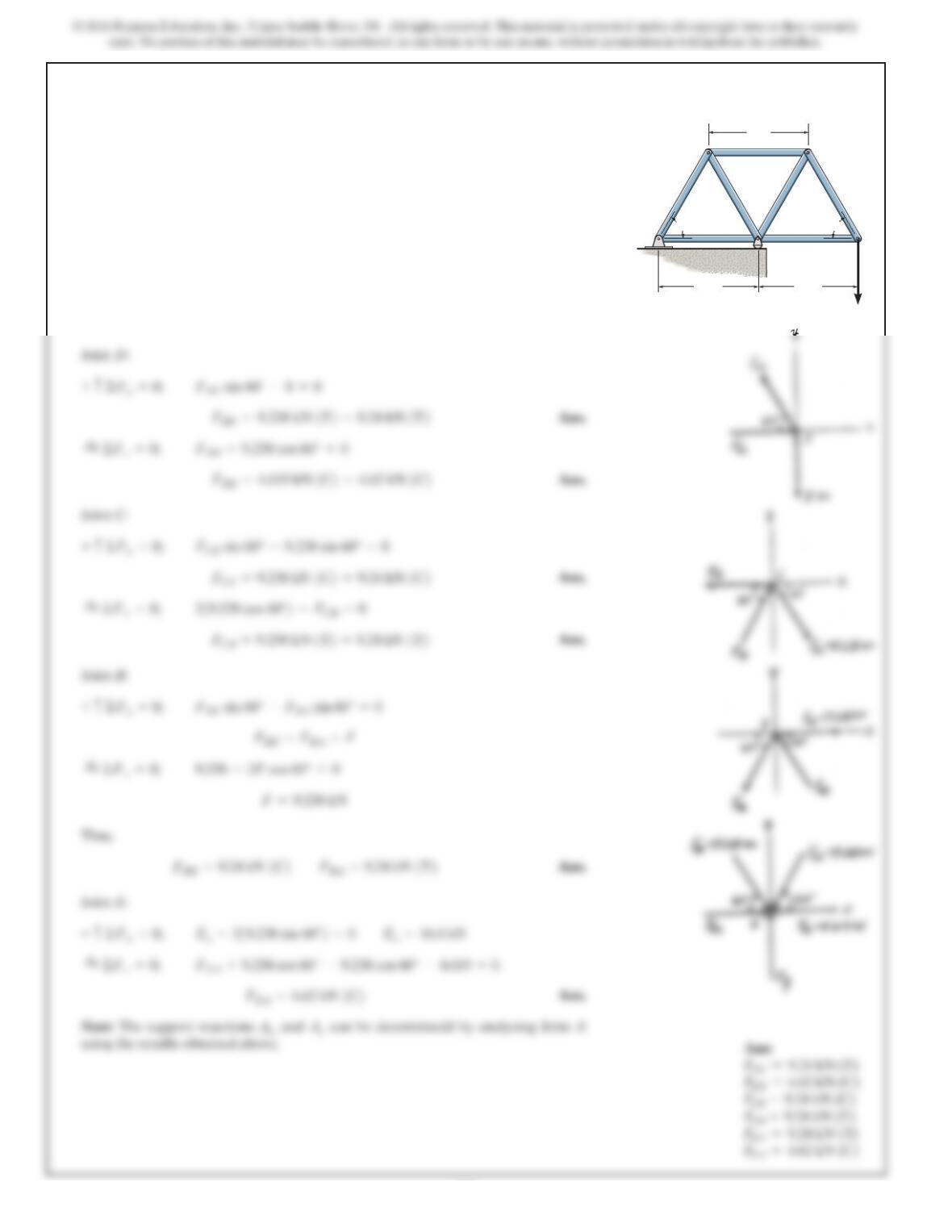
6–11.
Determine the force in each member of the Pratt truss, and
state if the members are in tension or compression.
SOLUTION
Joint A:
Joint L:
Joint C:
Joint K:
Joint J:
Due to Symmetry
Ans.
F
AL =F
GH =F
LK =F
HI =28.3 kN (C)
23.57 sin 45° –F
JI sin 45° =0©F
x=0;
:
+
10 sin 45° –F
KD cos (45° –26.57°) =0R+©F
x–0;
F
+
F
LC =0R+©F
x=0;
F
AL =28.28 kN (C)
20 –F
AL sin 45° =0+c©F
y=0;
A
BCDEF
G
H
I
J
K
L
2 m
2 m
2 m 2 m
2 m 2 m 2 m
2 m
2 m
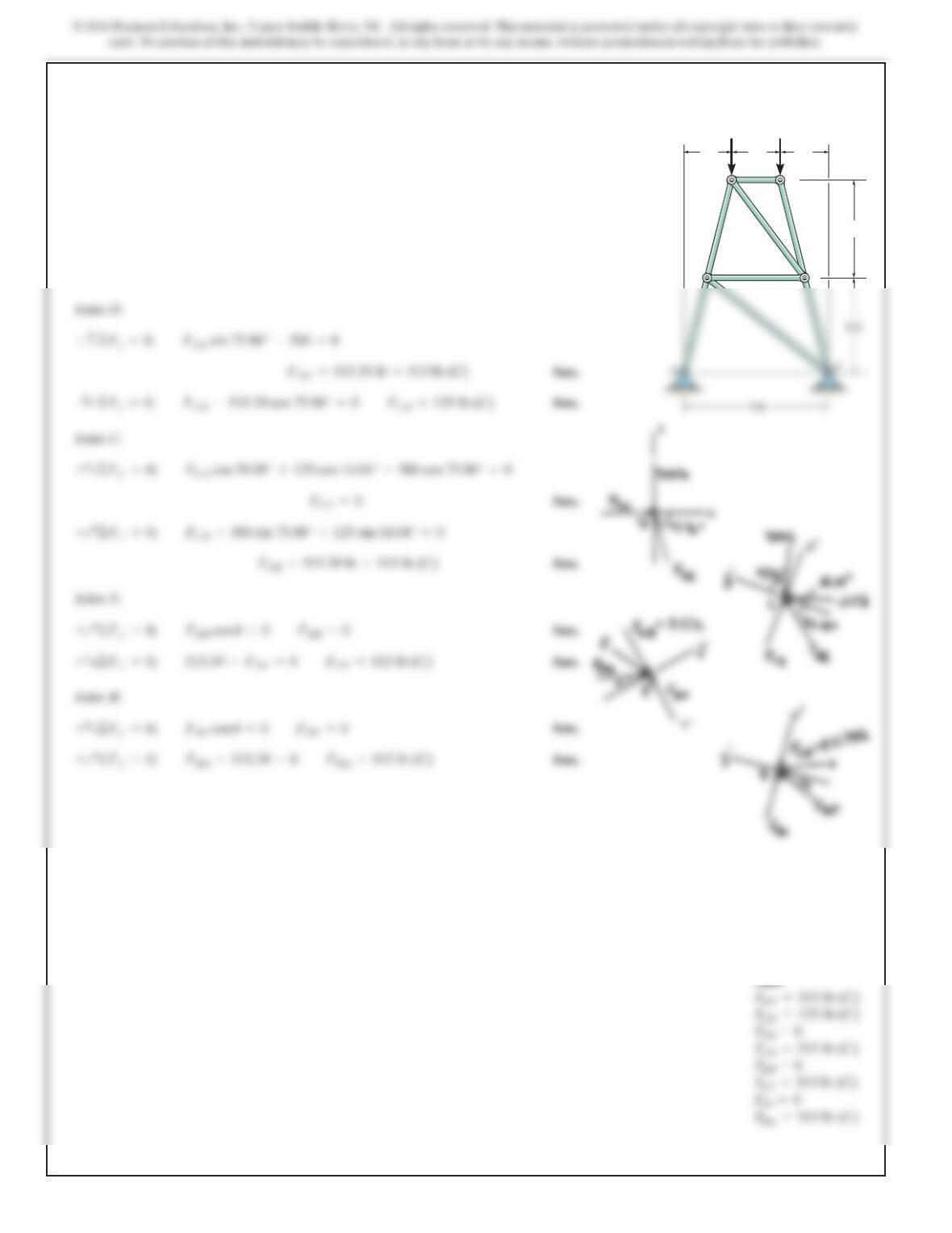
496
*6–12.
SOLUTION
Joint D:
Joint C:
Joint E:
Ans.
+Q©Fy¿=0; FEB cos u=0FEB =0
+Q©Fx¿=0; FCB –500 sin 75.96° –125 sin 14.04° =0
+c©Fy=0; FDE sin 75.96° –500 =0
Determine the force in each member of the truss and state
if the members are in tension or compression.
500 lb
3 ft
500 lb
C
B
E
D
6 ft
6 ft
3 ft 3 ft
Ans:
FDE =515 lb (C)
FCD =125 lb (C)
FCB =515 lb (C)
497
6–13.
SOLUTION
Joint A:
Joint D:
:
+©Fx=0; 4
214 (FAD)–1
22FAB =0
Determine the force in each member of the truss in terms of
the load Pand state if the members are in tension or
compression.
B
D
P
A
C
a a
a
a
3
—
4
1
—
4
Ans:
FCD =FAD =0.687P (T)
FCB =FAB =0.943P (C)
FDB =1.33P (T)
498
6–14.
Members AB and BC can each support a maximum
compressive force of 800 lb,and members AD,DC,and BD
can support a maximum tensile force of 1500 lb.If ,
determine the greatest load Pthe truss can support.
a=10 ft
SOLUTION
Joint A:
Joint D:
+c©Fy=0; –848.5297 –583.0952(2)
¢
1
217
≤
+FDB =0
:
+©Fx=0; –800
¢
1
22
≤
+FAD
¢
4
217
≤
=0
B
D
P
A
C
a
a
3
—
4
1
—
4
6–15.
Members AB and BC can each support a maximum
compressive force of 800 lb, and members AD, DC, and BD
can support a maximum tensile force of 2000 lb. If a = 6 ft,
determine the greatest load P the truss can support.
B
D
A
C
a a
a
a
3
—
4
1
—
4
SOLUTION
Joint A:
S
+
ΣF
x=
0; –800
a1
22b
+FAD
a4
217 b
=0
+
c
Joint D:
+
c
ΣF
y
=0;
–848.5297 –583.0952(2)
+FDB =0
500
*6–16.
SOLUTION
Method of Joints: In this case, the support reactions are not required for
determining the member forces.
Joint D:
Joint B:
Thus,
Note: The support reactions and can be determinedd by analyzing Joint A
using the results obtained above.
A
y
A
x
F
BE
sin 60° –F
BA
sin 60° =0+c©F
y
=0;
F
CE
sin 60° –9.238 sin 60° =0+c©F
y
=0;
F
DE
–9.238 cos 60° =0:
+©F
x
=0;
F
DC
sin 60° –8=0+c©F
y
=0;
Determine the force in each member of the truss. State
whether the members are in tension or compression. Set
P=8 kN.
60••
60••
4m 4m
B
ED
C
A
4m
P
Ans: