222
Problem Set 6.1
1. Determine the equivalent resistance Req for the circuit shown in Figure 6.8.
Figure 6.8 Problem 1.
Solution
The equivalent resistance for the parallel-connected resistors R1and R3is
eq1 1 3
111
RRR
or
13
eq1
13
RR
RRR
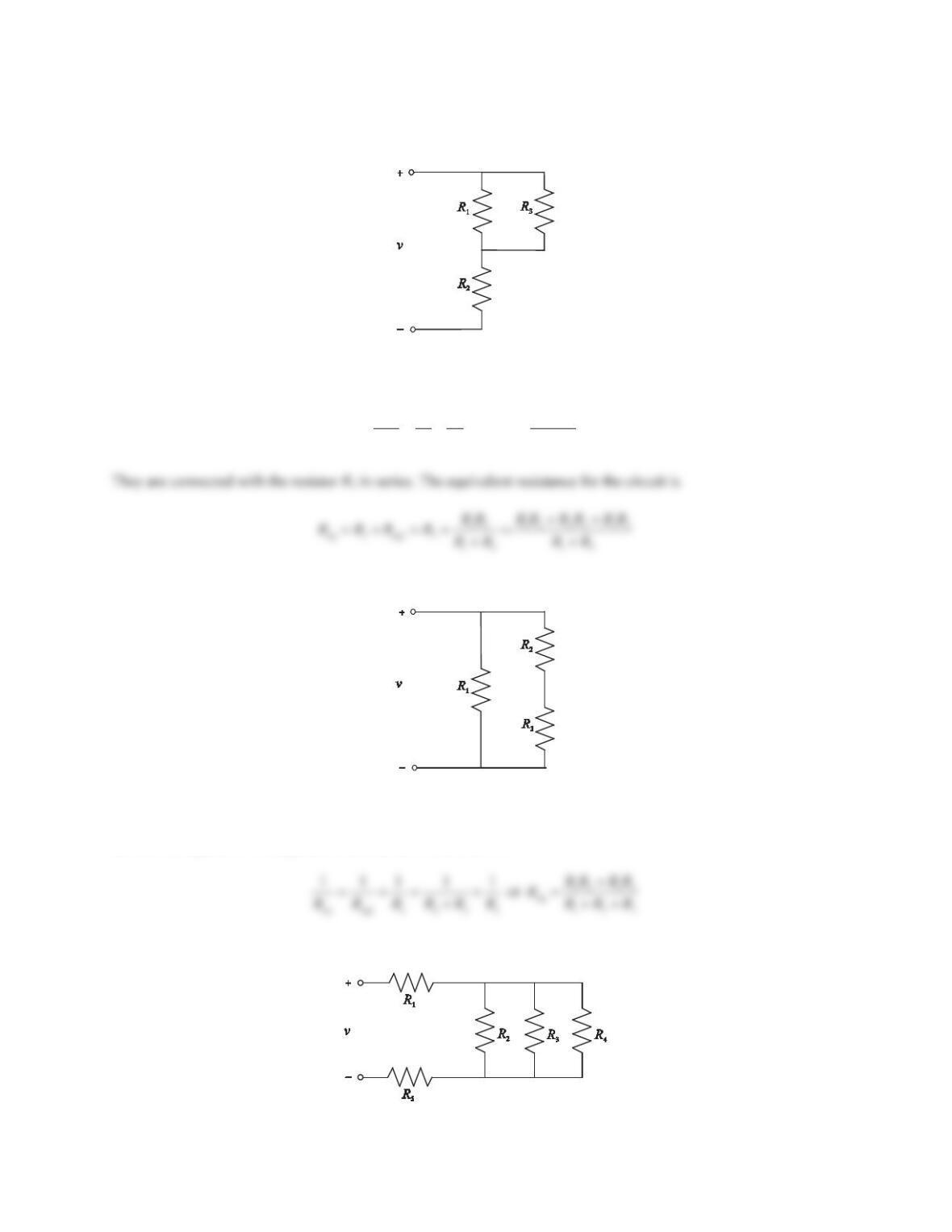
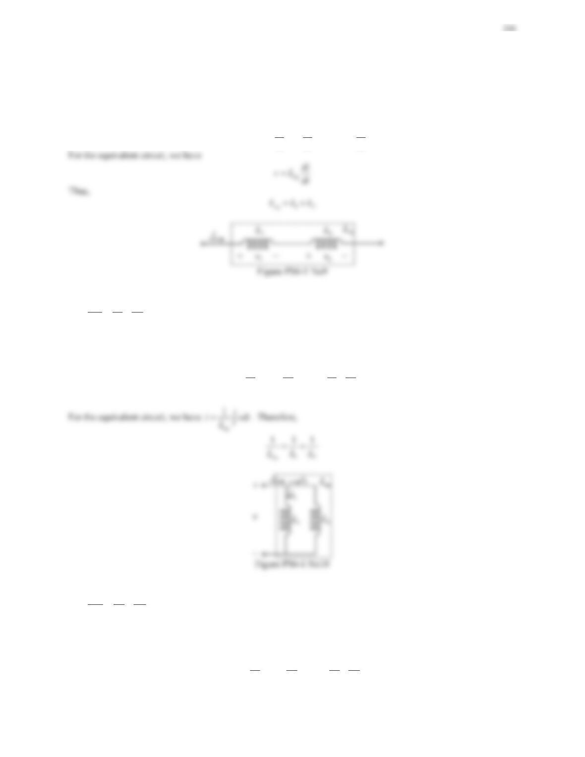
2. Determine the equivalent resistance Req for the circuit shown in Figure 6.9.
Figure 6.9 Problem 2.
Solution
The equivalent resistance for the series-connected resistors R2and R3is
eq1 2 3
RRR
. They are connected with the
resistor R1in parallel. The equivalent resistance for the circuit is
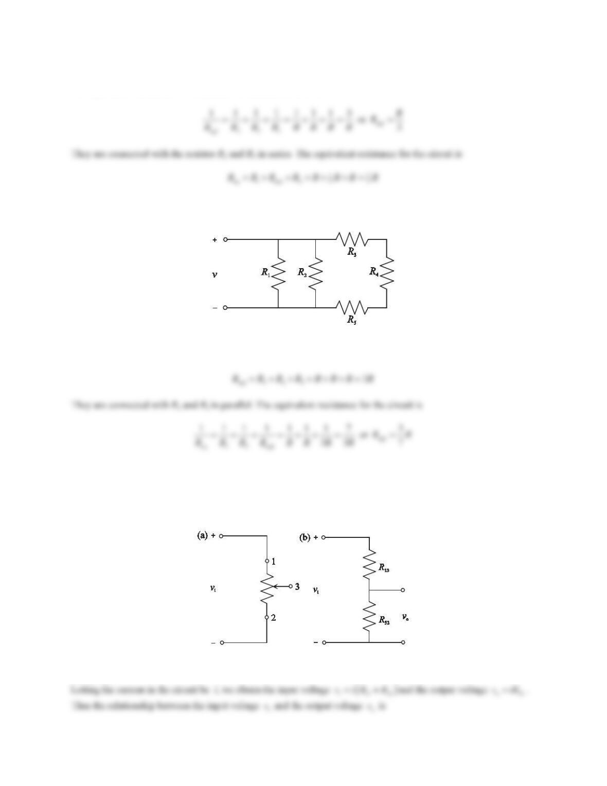
3. Determine the equivalent resistance Req for the circuit shown in Figure 6.10. Assume that all resistors have the
same resistance of R.
Figure 6.10 Problem 3.
223
Solution
The equivalent resistance for the parallel-connected resistors is
4. Determine the equivalent resistance Req for the circuit shown in Figure 6.11. Assume that all resistors have the
same resistance of R.
Figure 6.11 Problem 4.
Solution
The resistors R3,R4, and R5are connected in series and the equivalent resistance is
5. A potentiometer is a variable resistor with three terminals. Figure 6.12a shows a potentiometer connected to a
voltage source. The two end terminals are labeled as 1 and 2, and the adjustable terminal is labeled as 3. The
potentiometer acts as a voltage divider, and the total resistance is separated into two parts as shown in Figure
6.12b, where R13 is the resistance between terminal 1 and terminal 3, and R32 is the resistance between terminal
3 and terminal 2. Determine the relationship between the input voltage viand the output voltage vo.
Figure 6.12 Problem 5. (a) Potentiometer and (b) voltage divider.
Solution
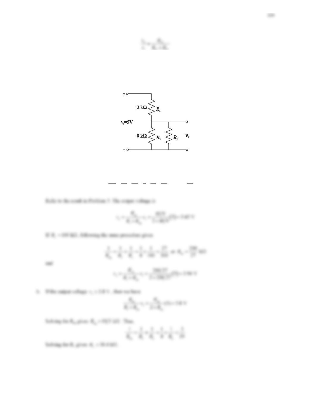
6. The output voltage of a voltage divider is not fixed but varies according to the load.
a. Find the output voltage voin Figure 6.13 for two different values of load resistance: (1) RL=10Nȍ and (2)
RL= 100 Nȍ.
b. If the output voltage vomust be greater than 3.8V, determine the minimum value of the load resistance.
Figure 6.13 Problem 6.
Solution
a. If L10 kR :
, then the equivalent resistance for the parallel-connected resistors is
b.
eq 2 L
111119
810 40RRR
or
eq
40 k
9
R :
7. Consider an inductive divider shown in Figure 6.14. For an AC input vi, prove that the output voltage of the
inductive voltage divider is
1
2
oi
2
L
vv
LL
.
Solution
Denoting the current in the circuit to be i, we obtain the input voltage
i1 2 12
di di di
vL L LL
dt dt dt
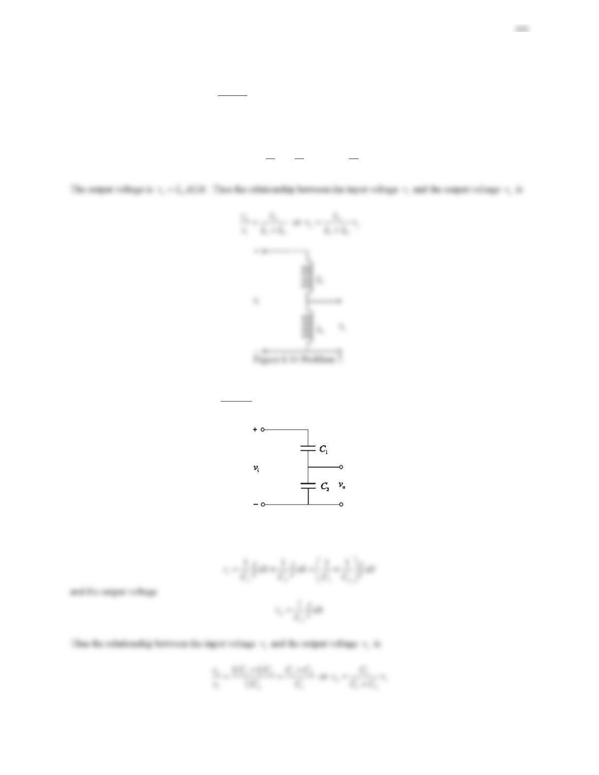
8. Consider a capacitive divider shown in Figure 6.15. For an AC input vi, prove that the output voltage of the
capacitive voltage divider is 1
1
oi
2
v
C
vCC
.
Figure 6.15 Problem 8.
Solution
Denoting the current in the circuit to be i, we obtain the input voltage
9. Consider a circuit of two inductors, L1and L2, in series. Prove that the equivalent inductance of the circuit is Leq
=L1+L2.
Solution
As shown in the figure below, for two inductors in series, we have
12 1 2 1 2
di di di
vv v L L L L
dt dt dt
10. Consider a circuit of two inductors, L1and L2, in parallel. Prove that the equivalent inductance of the circuit is
eq 1 2
111
LLL
.
Solution
As shown in the figure below, for two inductors in parallel, we have
12
12 12
11 11
i i i vdt vdt vdt
LL LL
§·
¨¸
©¹
³³ ³
11. Consider a circuit of two capacitors, C1and C2, in series. Prove that the equivalent capacitance of the circuit is
eq 1 2
111
CCC
.
Solution
As shown in the figure below, for two capacitors in series, we have
12
12 12
11 11
v v v idt idt idt
CC CC
§·
¨¸
©¹
³³ ³
12. Consider a circuit of two capacitors, C1and C2, in parallel. Prove that the equivalent capacitance of the circuit is
Ceq =C1+C2.
Solution
As shown in the figure below, for two capacitors in parallel, we have
12 1 2 1 2
dv dv dv
ii i C C C C
dt dt dt
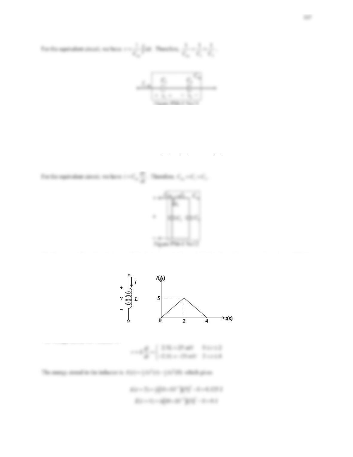
13. The current through an inductor of 10 mH is shown in Figure 6.16. Find the voltage across the inductor. What is
the energy stored in the inductor when (1) t=2sand(2)t=4s?
Figure 6.16 Problem 13.
Solution
The voltage across the inductor is
14. The voltage across a capacitor of 100 ȝ) is shown in Figure 6.17. Find the current through the capacitor. What
is the energy stored in the capacitor when (1) t=3sand(2)t=4s?
Solution
The current through the capacitor is
003
10 1 mA 3 4
t
dv
iC Ct
dt
dd
® d
¯
Problem Set 6.2
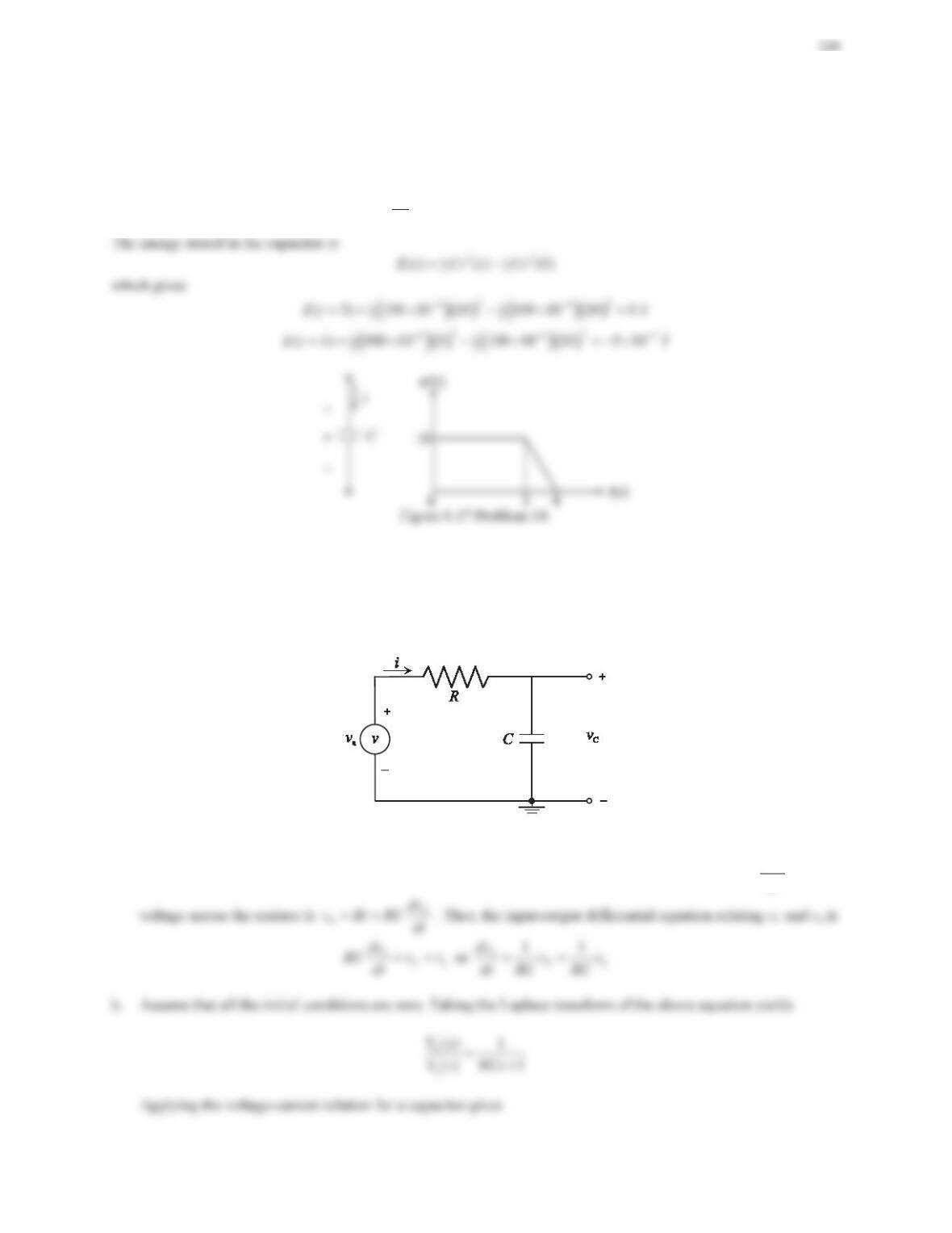
1. Consider the first-order RC circuit shown in Figure 6.24.
a. Derive the input–output differential equation relating vCand va.
b. Determine the transfer function I(s)/Va(s), which relates the loop current i(t) to the applied voltage va(t).
Assume that all the initial conditions are zero.
Figure 6.24 Problem 1.
Solution
a. Applying Kirchhoff’s voltage law to the single loop gives
RC a
vvv
. The loop current is C
dv
iC
dt
and the
229
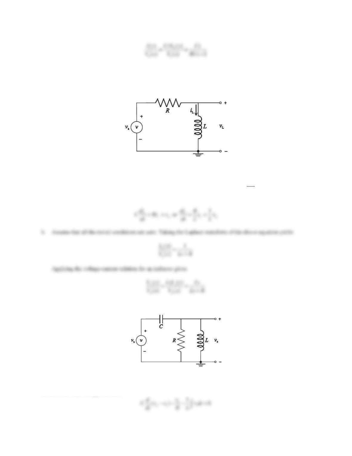
2. Consider the first-order RL circuit shown in Figure 6.25.
a. Derive the input–output differential equation relating iLand va.
b. Determine the transfer function VL(s)/Va(s), which relates the voltage across the inductor vL(t) to the applied
voltage va(t). Assume that all the initial conditions are zero.
Figure 6.25 Problem 2.
Solution
a. Applying Kirchhoff’s voltage law to the single loop gives
RLa
vvv
. Note that the loop current is iL. The
voltage across the resistor is
RL
vRi
and the voltage across the inductor is
L
L
di
vL
dt
. Thus, the input-output
differential equation relating iLand vais
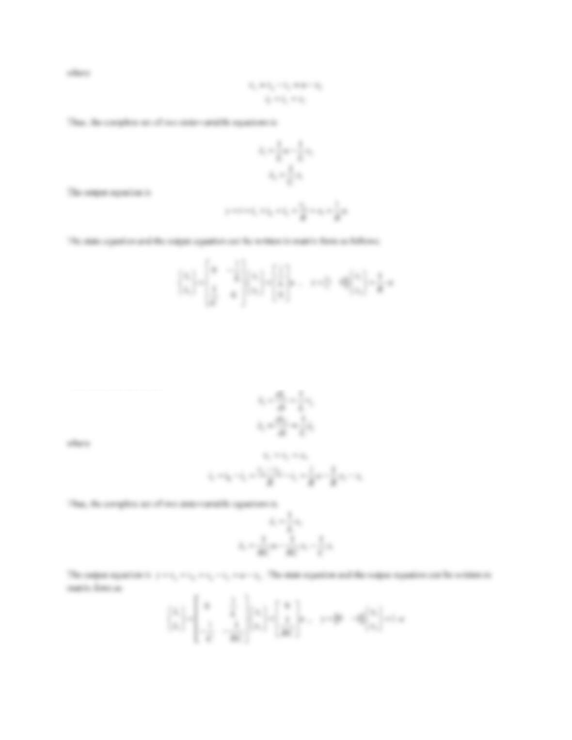
3. Consider the circuit shown in Figure 6.26. Use the node method to derive the input–output differential equation
relating voand va.
Figure 6.26 Problem 3.
Solution
Applying Kirchhoff’s current law to node 1 gives
CRL
0iii
. Expressing the current through each element in
terms of the node voltage, we have
230
Differentiating the above equation with respect to time results in
4. Repeat Problem 3 using the loop method.
Solution
Assign loop currents as shown in the figure below.
231
Taking the Laplace transform of the differential equations gives
1a
2
()
1
)
()
0
(
Is
Rs Rs
Is
RLs
s
C
R
sV
ªº
½
½
«»
®¾® ¾
«»
¯¿
¯¿
¬¼
5. Consider the circuit shown in Figure 6.27. Use the node method to derive the input–output differential equation
relating iand va.
Figure 6.27 Problem 5.
Solution
232
1
2
a
() 1
() 1
Vs
Vs LCs
or
1a
2
1
() ()
1
Vs Vs
LCs
6. Repeat Problem 5 using the loop method.
Solution
Assign loop currents as shown in the figure below.
Figure PS6-2 No6
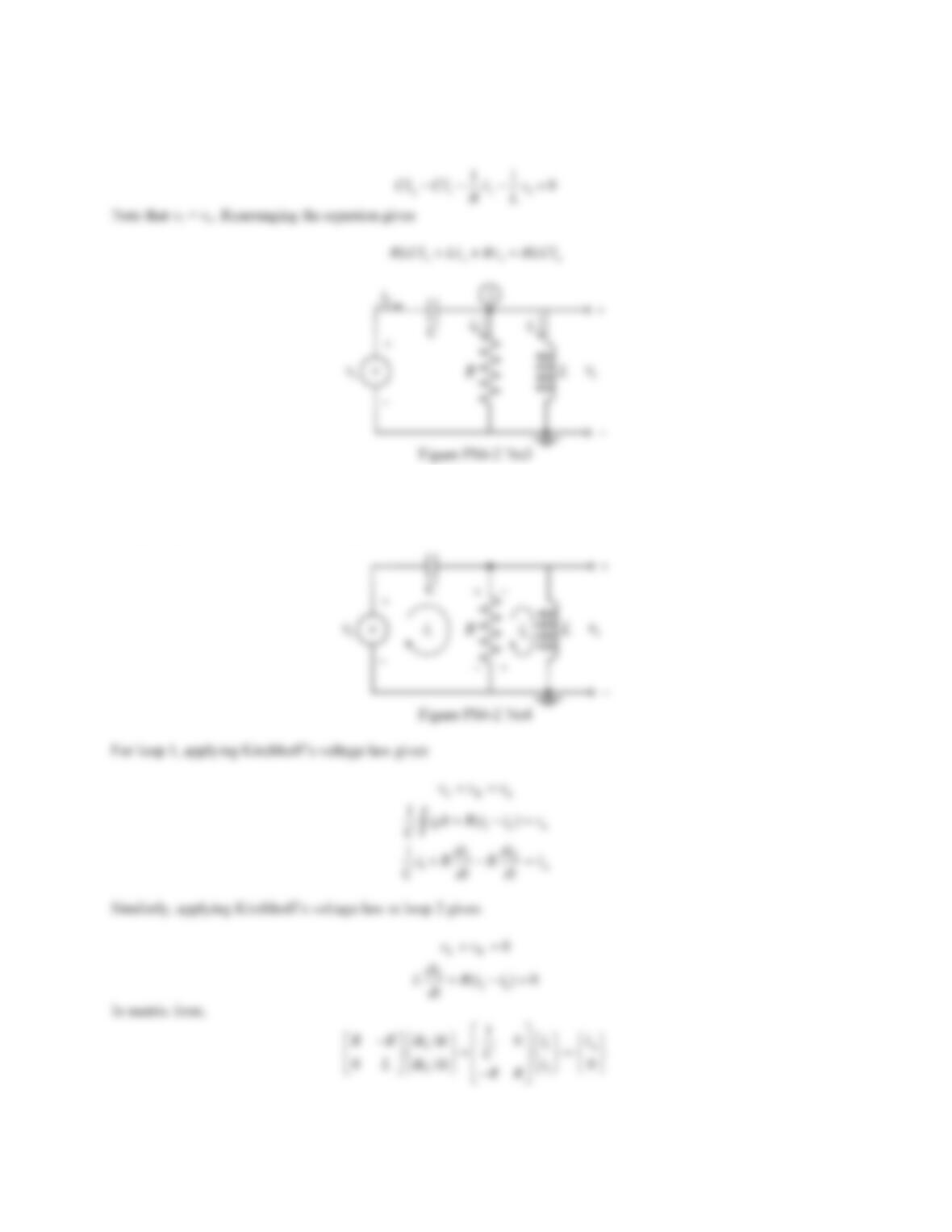
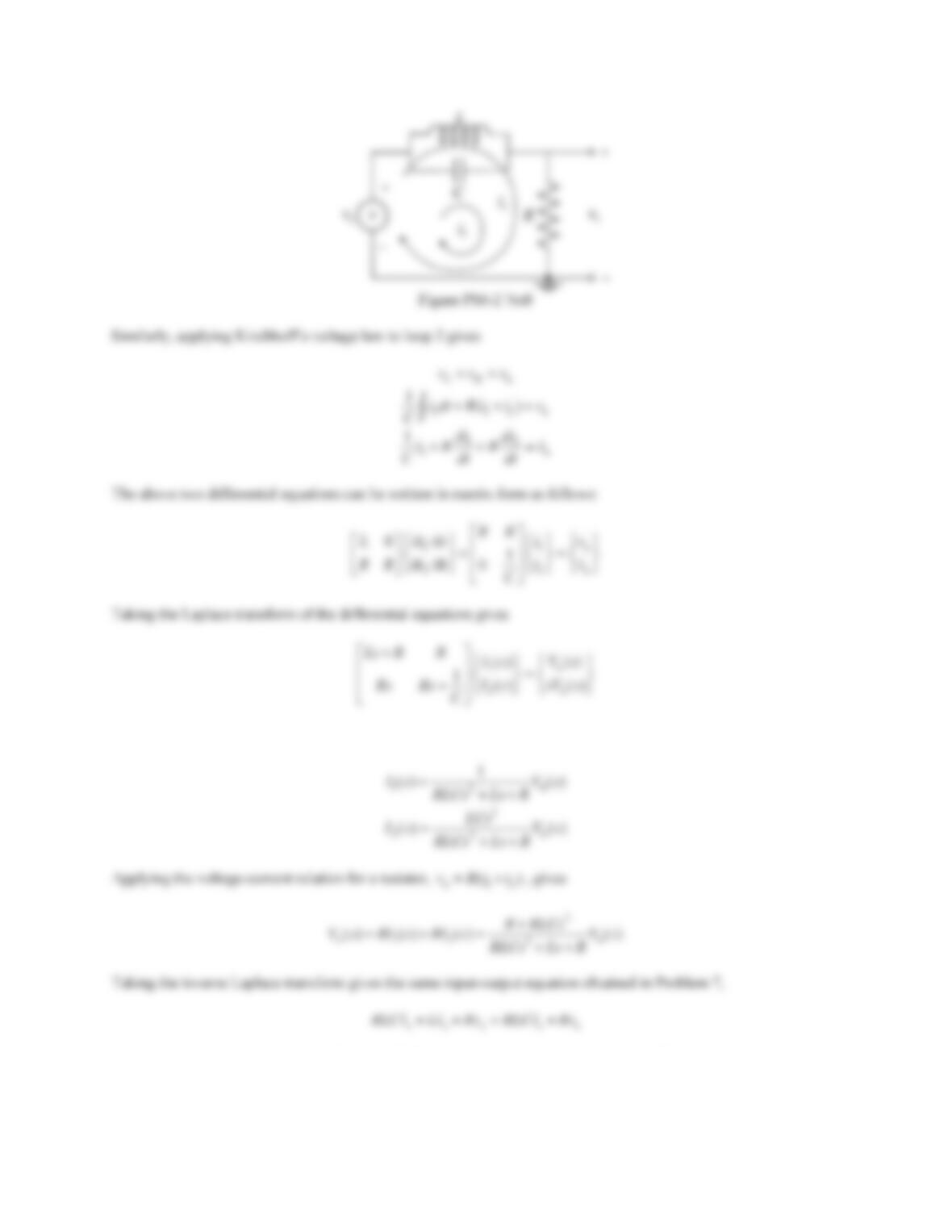
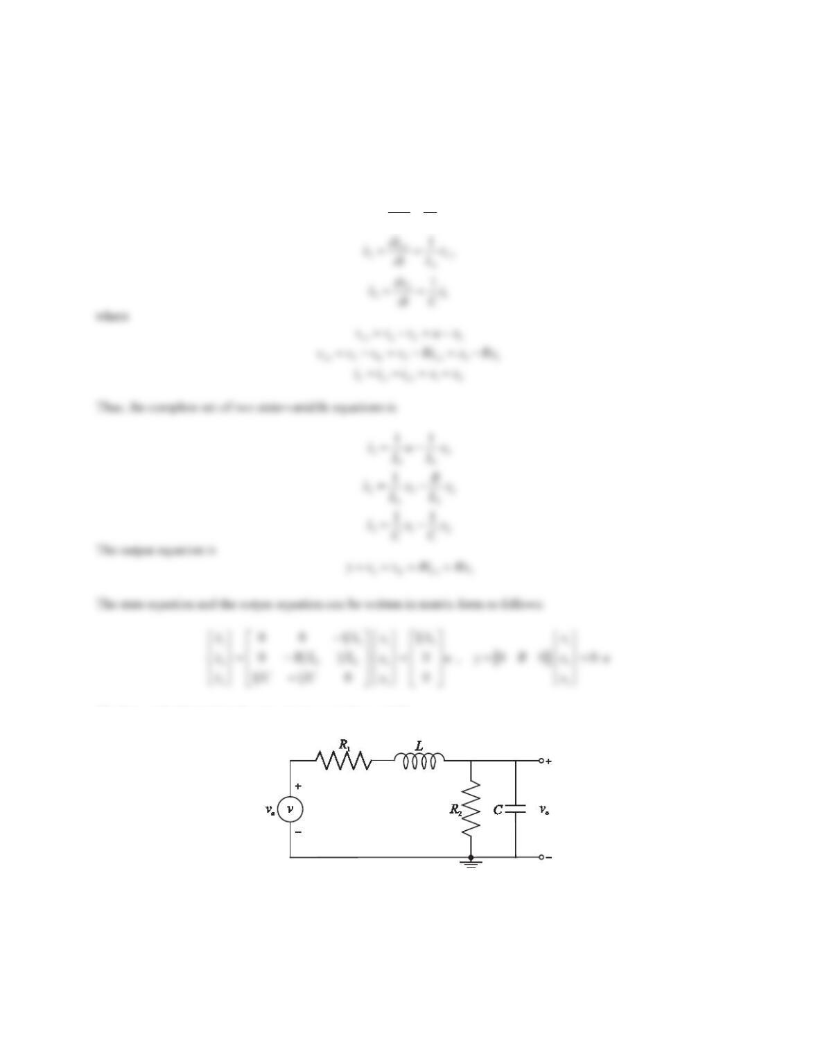
7. Consider the circuit shown in Figure 6.28. Use the node method to derive the input–output differential equation
relating voand va.
Figure 6.28 Problem 7.
Solution
Figure PS6-2 No7
8. Repeat Problem 7 using the loop method.
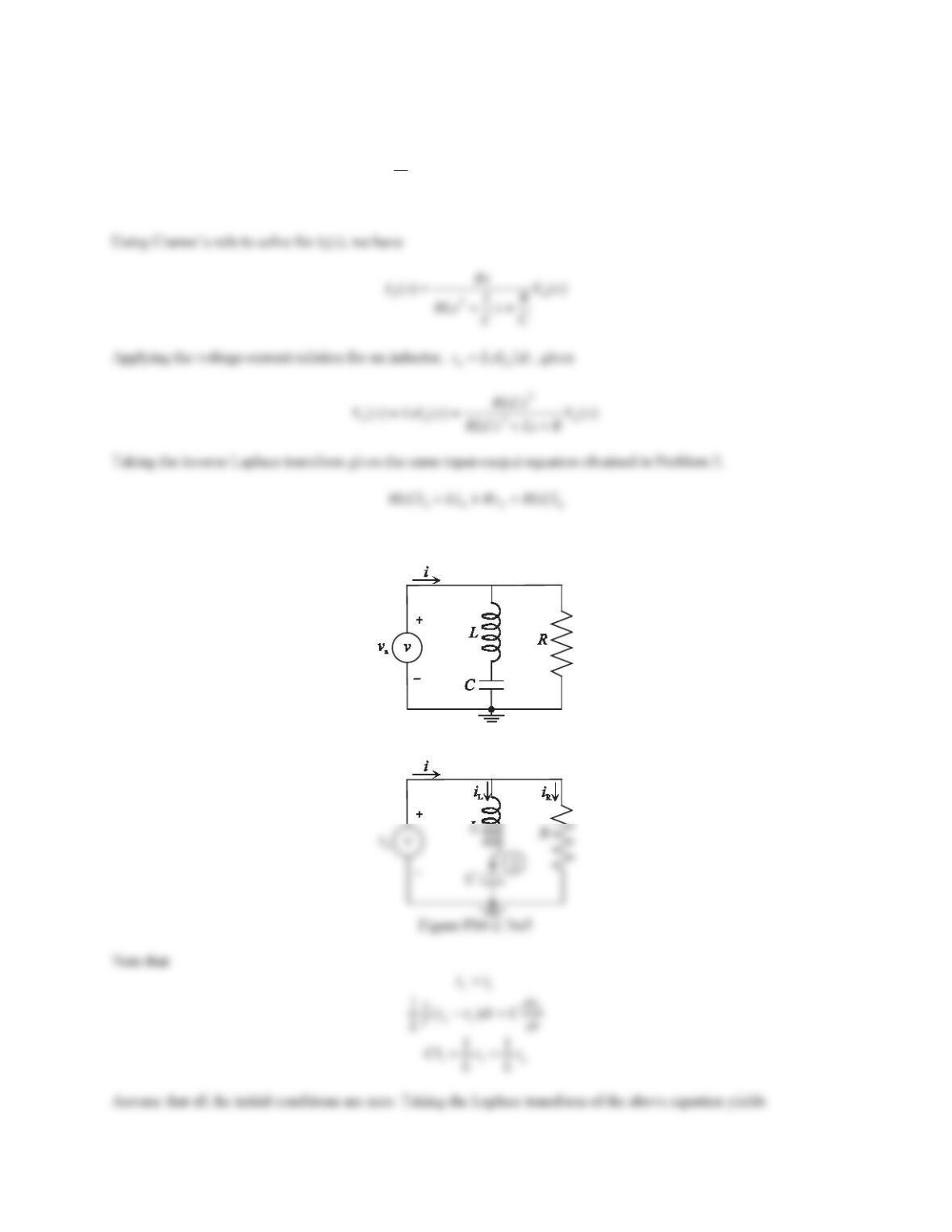
Solution
Assign loop currents as shown in the figure below. For loop 1, applying Kirchhoff’s voltage law gives
LR a
vv v
112 a
()
di
LRiiv
dt
234
Using Cramer’s rule to solve for I1(s)andI2(s), we have
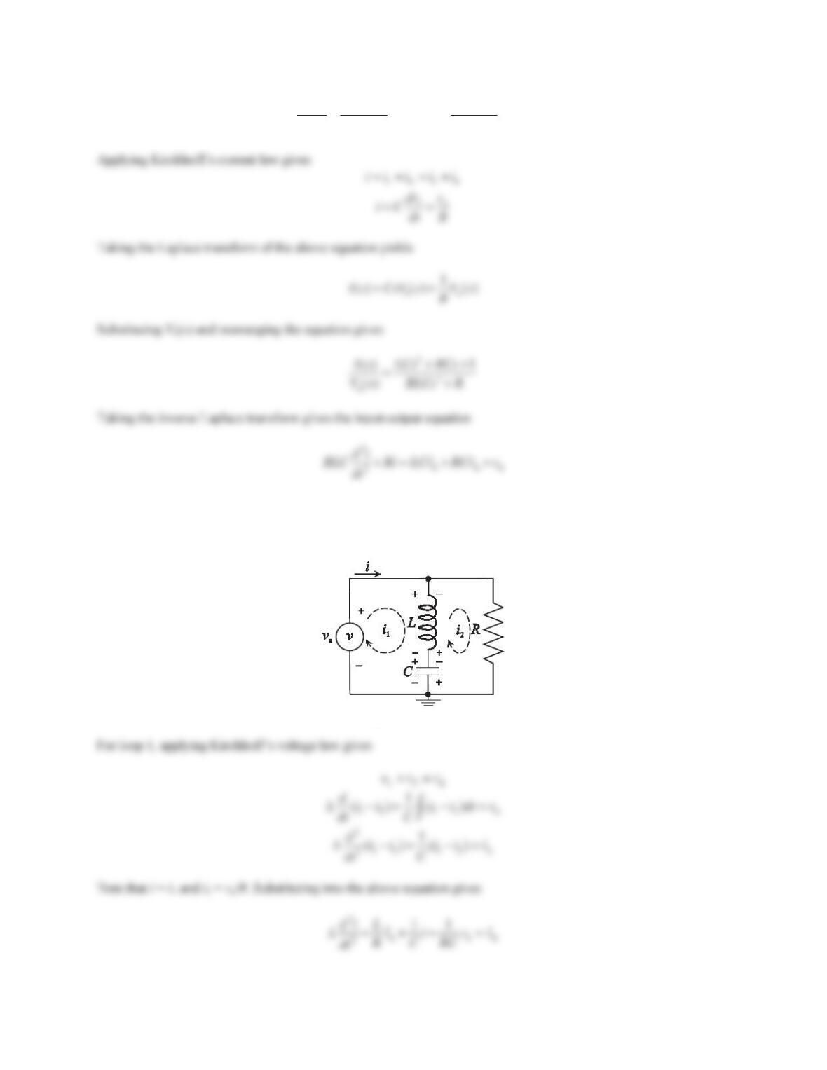
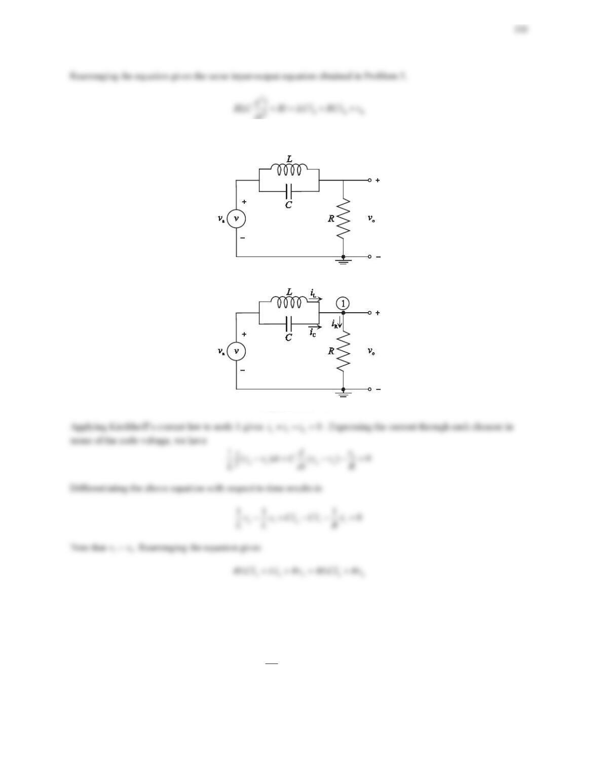
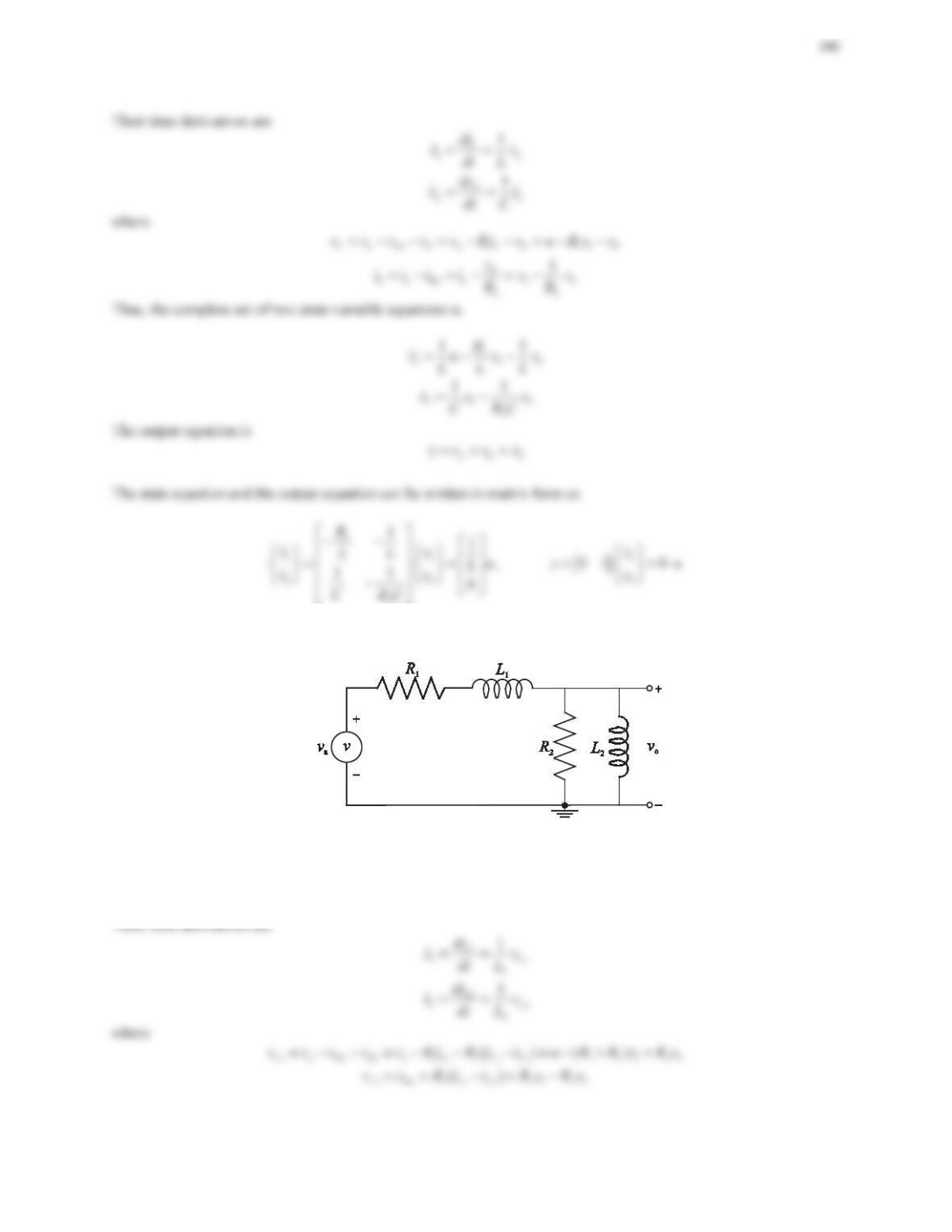
9. Consider the circuit shown in Figure 6.29. Use the node method to derive the differential equations for node
voltages. Determine the transfer function Vo(s)/ Va(s). Assume that all initial conditions are zero.
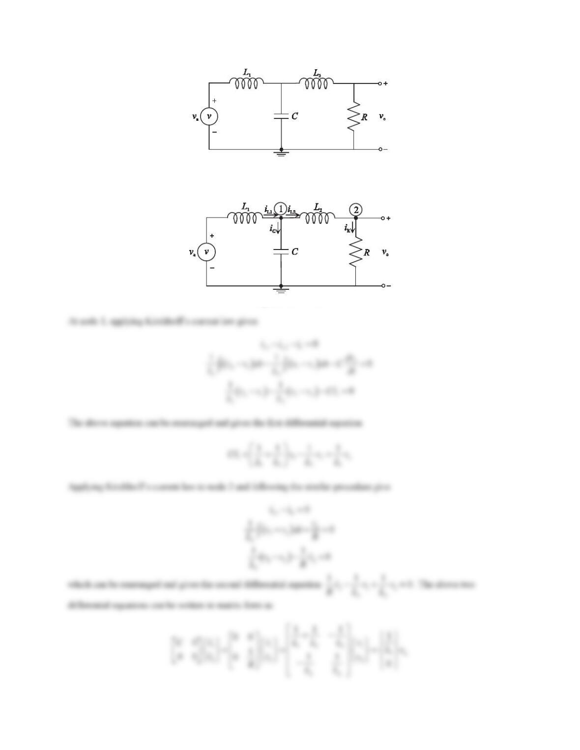
235
Figure 6.29 Problem 9.
Solution
All currents entering or leaving node 1 and node 2 are labeled as shown in the figure below.
Figure PS6-2 No9
236
Taking Laplace transform gives
2
1
12 2
1a
2
22
11 1 1
111 0
Cs Vs
LL L LVs
Vs
s
LRL
ªº
§·
½
«»
¨¸ ½
°°
©¹
«»
®¾®¾
«»
¯¿
°°
«»
¯¿
«»
¬¼
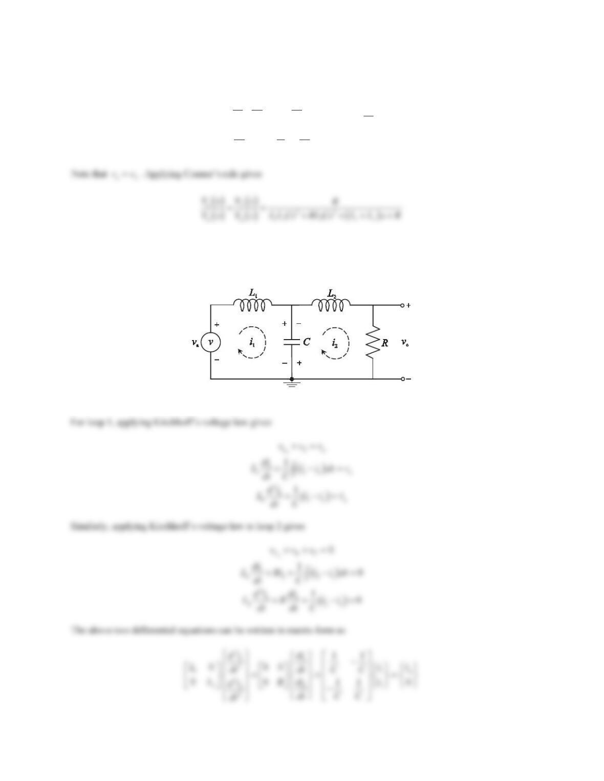
10. Reconsider the circuit shown in Figure 6.29. Use the loop method to derive the differential equations for loop
currents. Determine the transfer function Vo(s)/ Va(s). Assume that all initial conditions are zero.
Solution
Assign loop currents as shown in the figure below.
Figure PS6-2 No10
237
Taking Laplace transform gives
2
1
1a
22
2
11
11
0
Ls Is sV s
CC
Is
Ls Rs
CC
ªº
«»
½
½
«»
®¾® ¾
¯¿
«»
¯¿
«»
¬¼
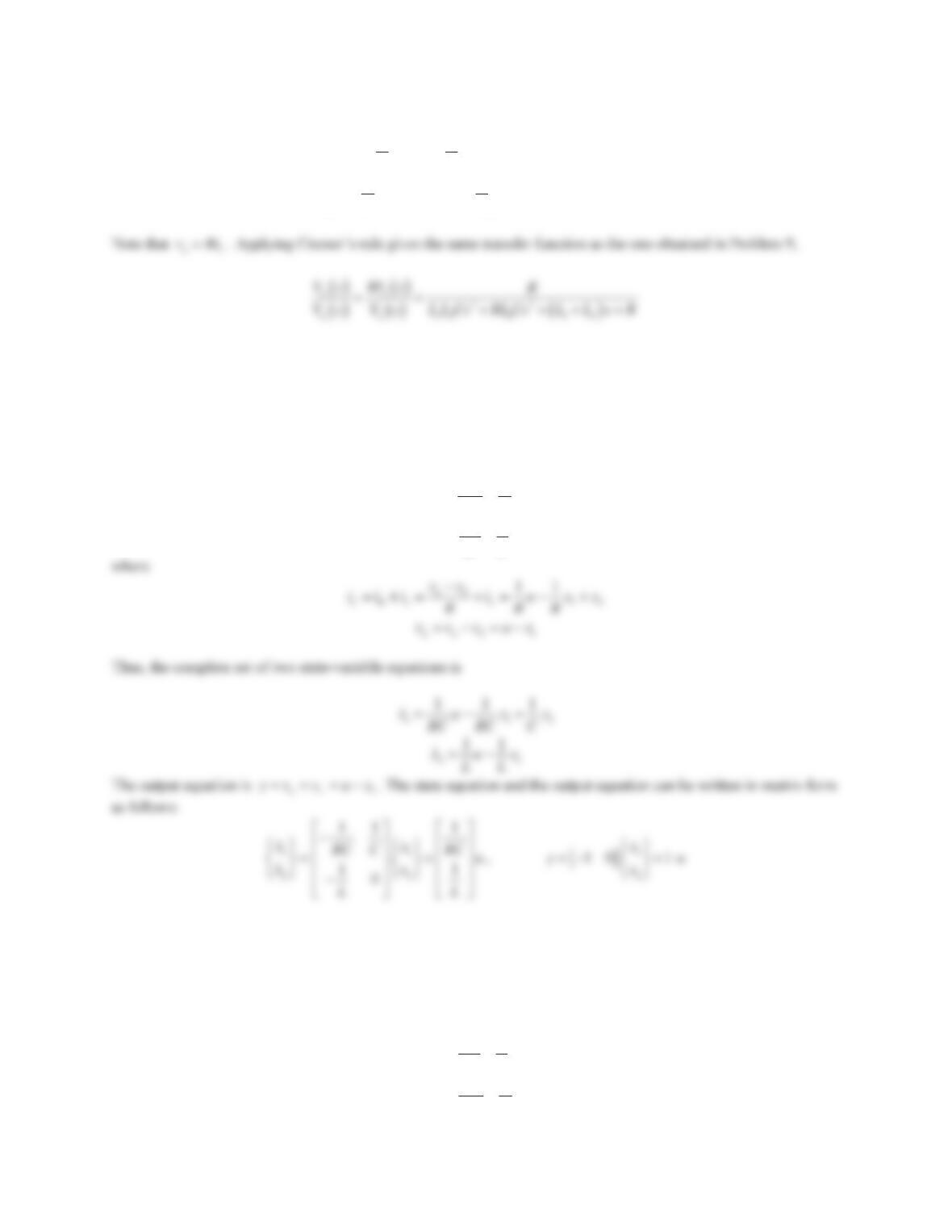
11. Consider the circuit shown in Figure 6.26. Determine a suitable set of state variables and obtain the state-space
representation with voas the output.
Solution
Refer to the figure shown in Problem 3. Note that the circuit has two energy storage elements, Cand L.Thisimplies
that two states are needed, and they are
1C 2L
,xv xi
Their time derivatives are
C
1C
1
dv
xi
dt C
L
2L
1
di
xv
dt L
12. Repeat Problem 11 for the circuit shown in Figure 6.27.
Solution
Refer to the figure shown in Problem 5. Note that the circuit has two energy storage elements, Land C. This implies
that two states are needed, and they are
1L 2 C
,xi x v
Their time derivatives are
L
1L
1
di
xv
dt L
C
2C
1
dv
xi
dt C
238
13. Repeat Problem 11 for the circuit shown in Figure 6.28.
Solution
Refer to the figure shown in Problem 7. Note that the circuit has two energy storage elements, Land C. This implies
that two states are needed, and they are
1L 2 C
,xi x v
Their time derivatives are
14. Repeat Problem 11 for the circuit shown in Figure 6.29.
239
Solution
Refer to the figure shown in Problem 9. Note that the circuit has three energy storage elements, L1,L2,andC. This
implies that three states are needed, and they are
1L1 2L2 3 C
,,xi xi xv
Their time derivatives are
L1
1L1
1
1
di
xv
dt L
15. Repeat Problem 9 for the circuit shown in Figure 6.30.
Figure 6.30 Problem 15.
Solution
Note that the circuit has two energy storage elements, Land C. This implies that two states are needed, and they are
1L 2 C
,xi x v
16. Repeat Problem 9 for the circuit shown in Figure 6.31.
Figure 6.31 Problem 16.
Solution
Note that the circuit has two energy storage elements, L1and L2. This implies that two states are needed, and they
are
1L1 2L2
,xi xi
241
Thus, the complete set of two state-variable equations is
Problem Set 6.3
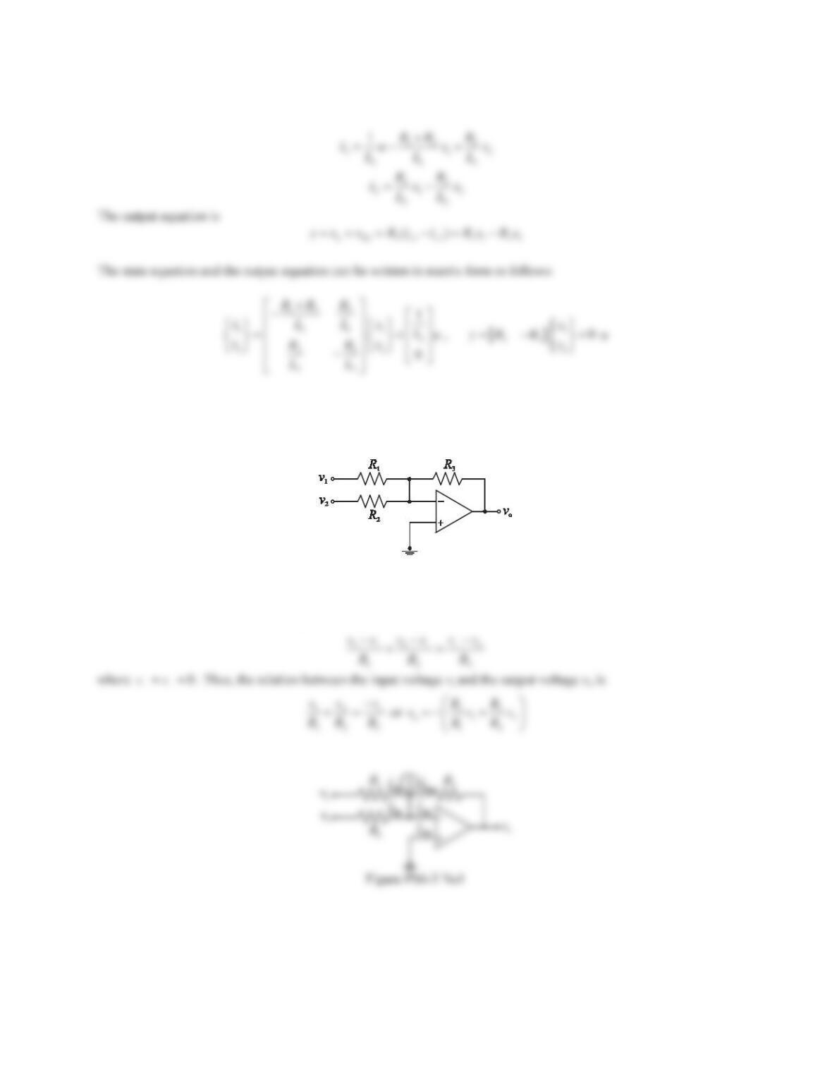
1. The op-amp circuit shown in Figure 6.37 is a summing amplifier. Determine the relation between the input
voltages v1,v2, and the output voltage vo.
Figure 6.37 Problem 1.
Solution
Applying Kirchhoff’s current law to node 1 gives 123 0iiii
. Because the current drawn by the op-amp is
very small, i.e.,
0i
|
, we have
12 3
ii i
. Using the voltage-current relation for each resistor yields
2. The op-amp circuit shown in Figure 6.38 is a difference amplifier. Determine the relation between the input
voltages v1,v2, and the output voltage vo.