Unlock document.
This document is partially blurred.
Unlock all pages and 1 million more documents.
Get Access
262
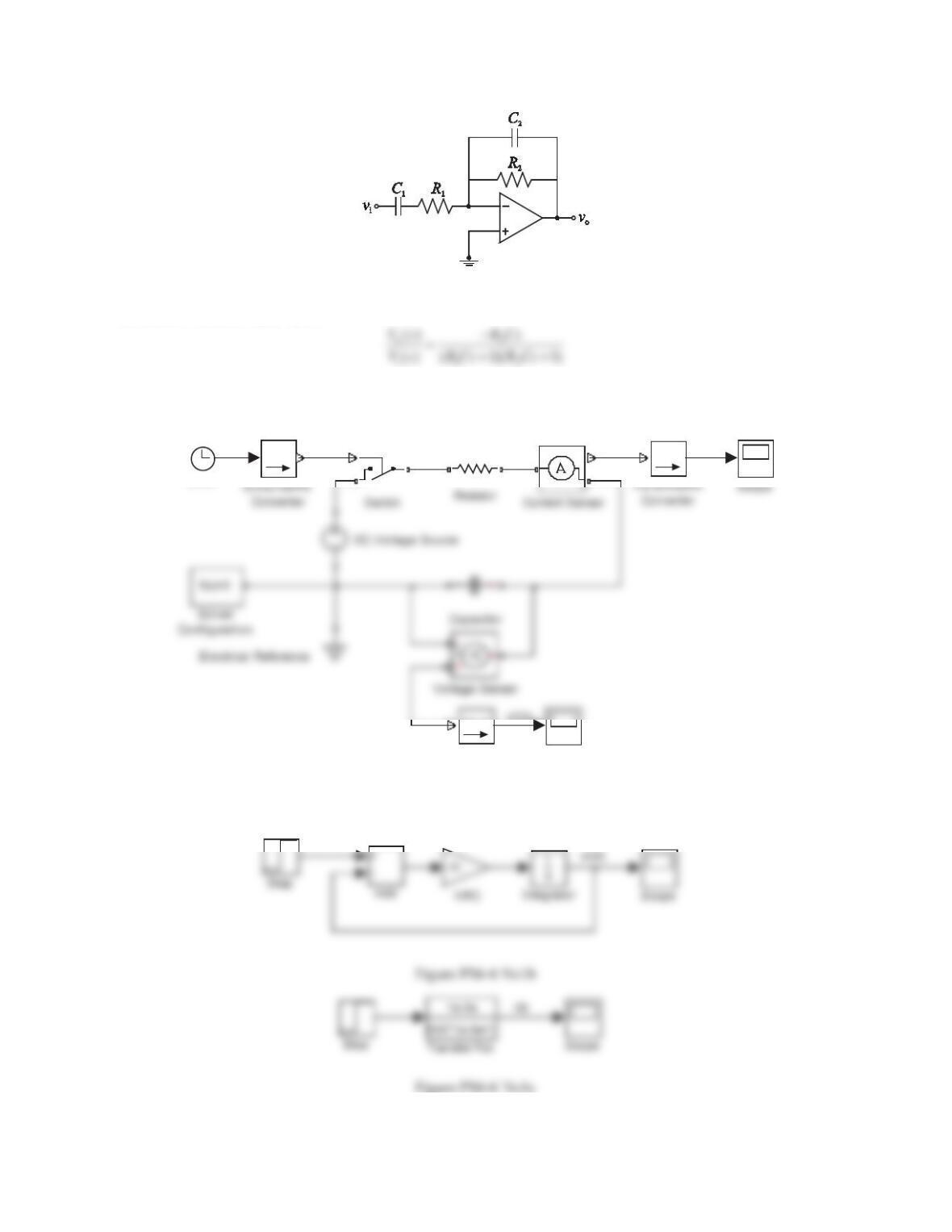
Figure 6.74 Problem 6.
Solution
The transfer function Vo(s)/Vi(s) is
MATLAB Figures
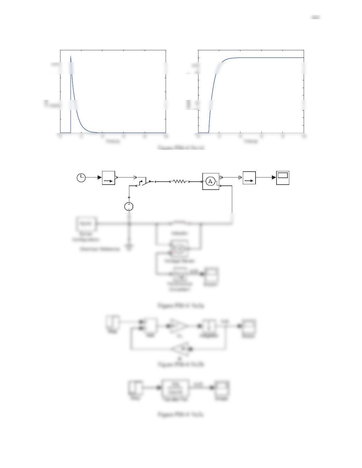
Problem 1
i(t)
PS
PSS
Scope1
+-
PS S
PS-Simulink
Converter1
PS S
I
+
-
Clock
Figure PS6-6 No1a
0.002
0.006
0.008
0.012
0.5
1
1.5
2.5
3
3.5
5
5.5
Problem 2
iL(t)
PS
Switch
PSS
Simulink-PS
Converter
Scope
+-
Re si st o r
PS S
PS-Simulink
Converter
DC Voltage Source
I
+
-
Current Sensor
Clock
0.02
0.04
0.08
0.12
0.16
0.18
0
2
5
6
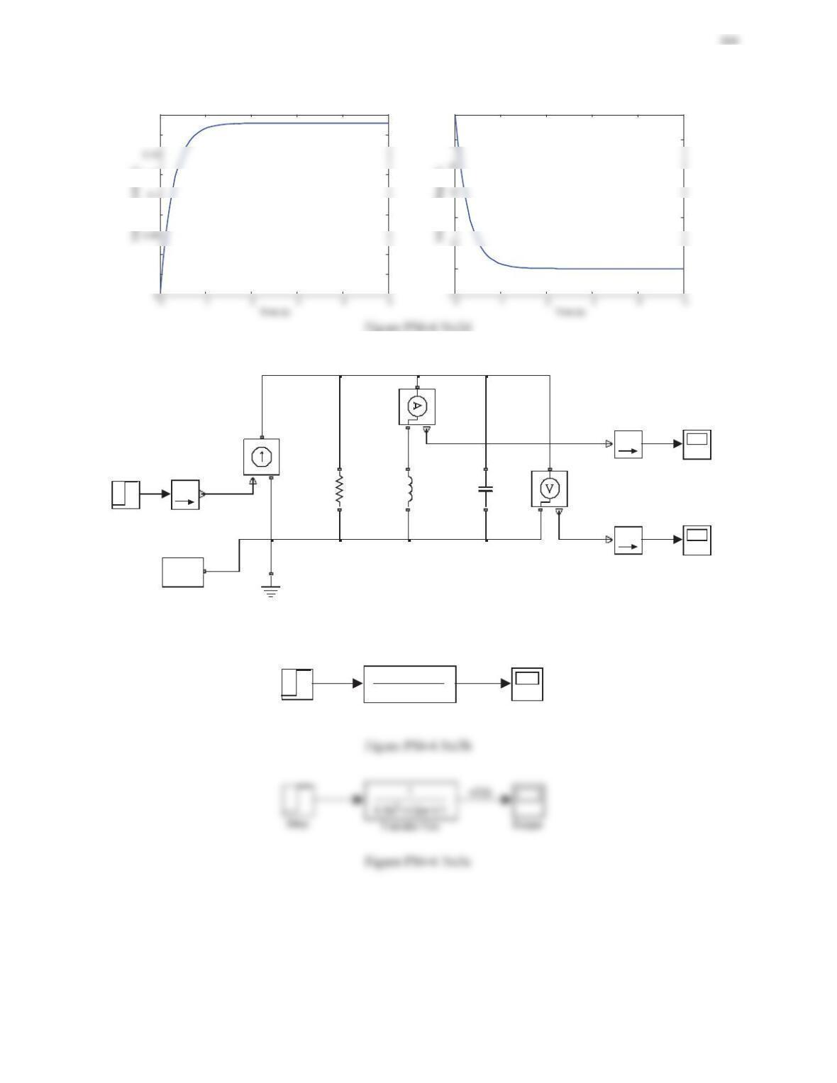
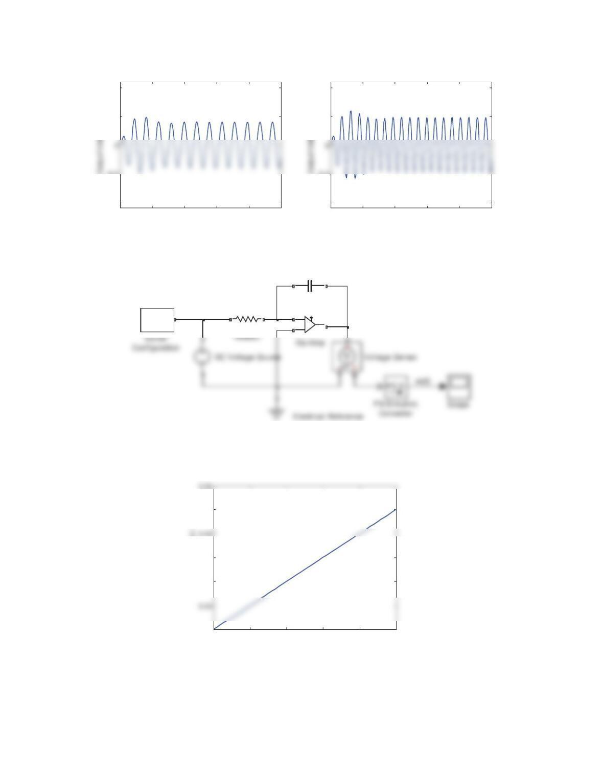
Problem 3
iL(t)
vC(t)
V
+
-
Voltage Sensor
Step
f(x)=0
Solver
Configuration
PSS
Simulink-PS
Converter
Scope1
Scope
+-
Re si st o r
PS S
PS-Simulink
Converter1
PS S
PS-Simulink
Converter
+-
Inductor
Electrical Reference
I
+
-
Current Sensor
Controlled Current
Source
+-
Capacitor
Figure PS6-6 No3a
vC(t)
s
0.5s +1/2s+1/1
2
Transfer Fcn
Step Scope
265
-2
10
2
14
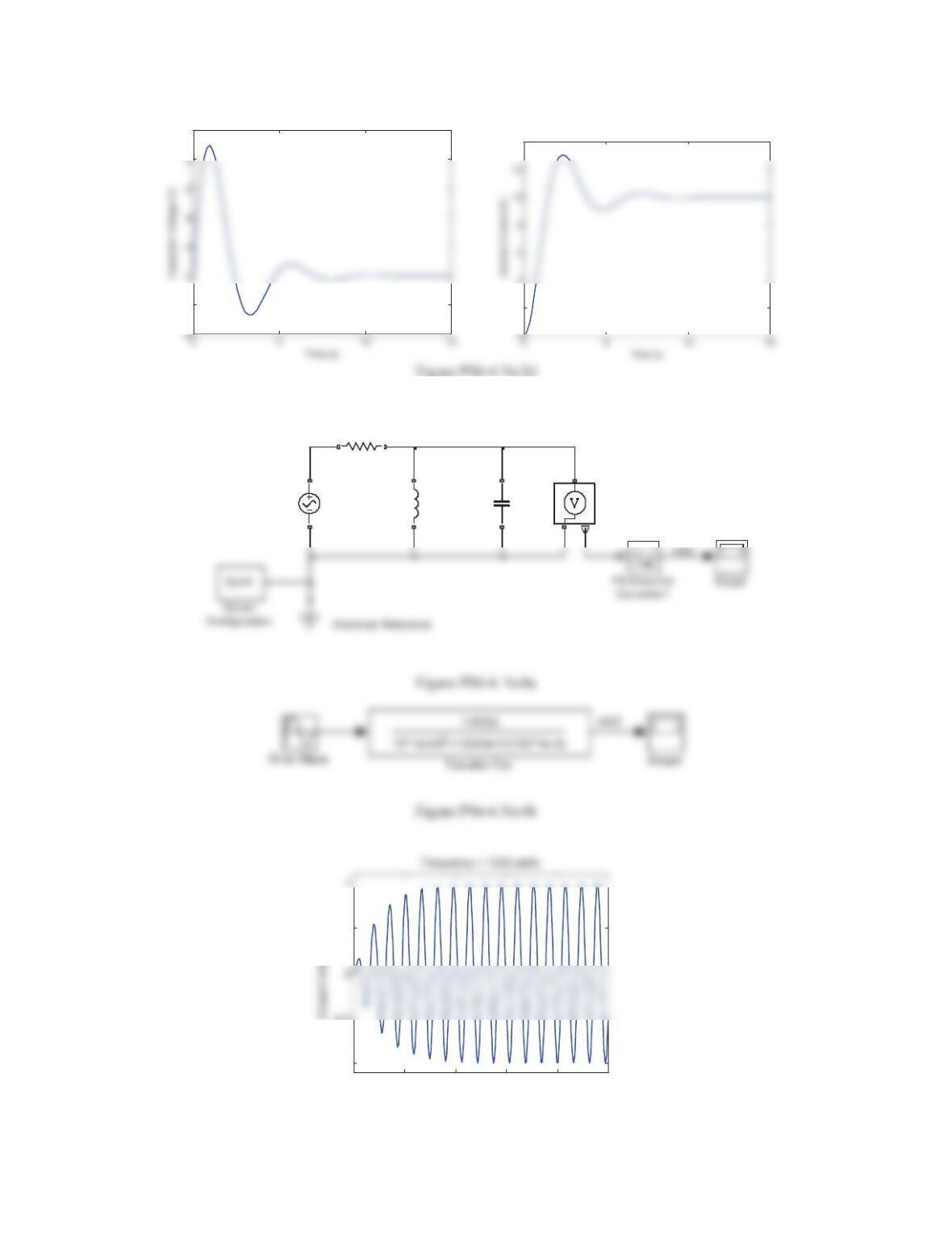
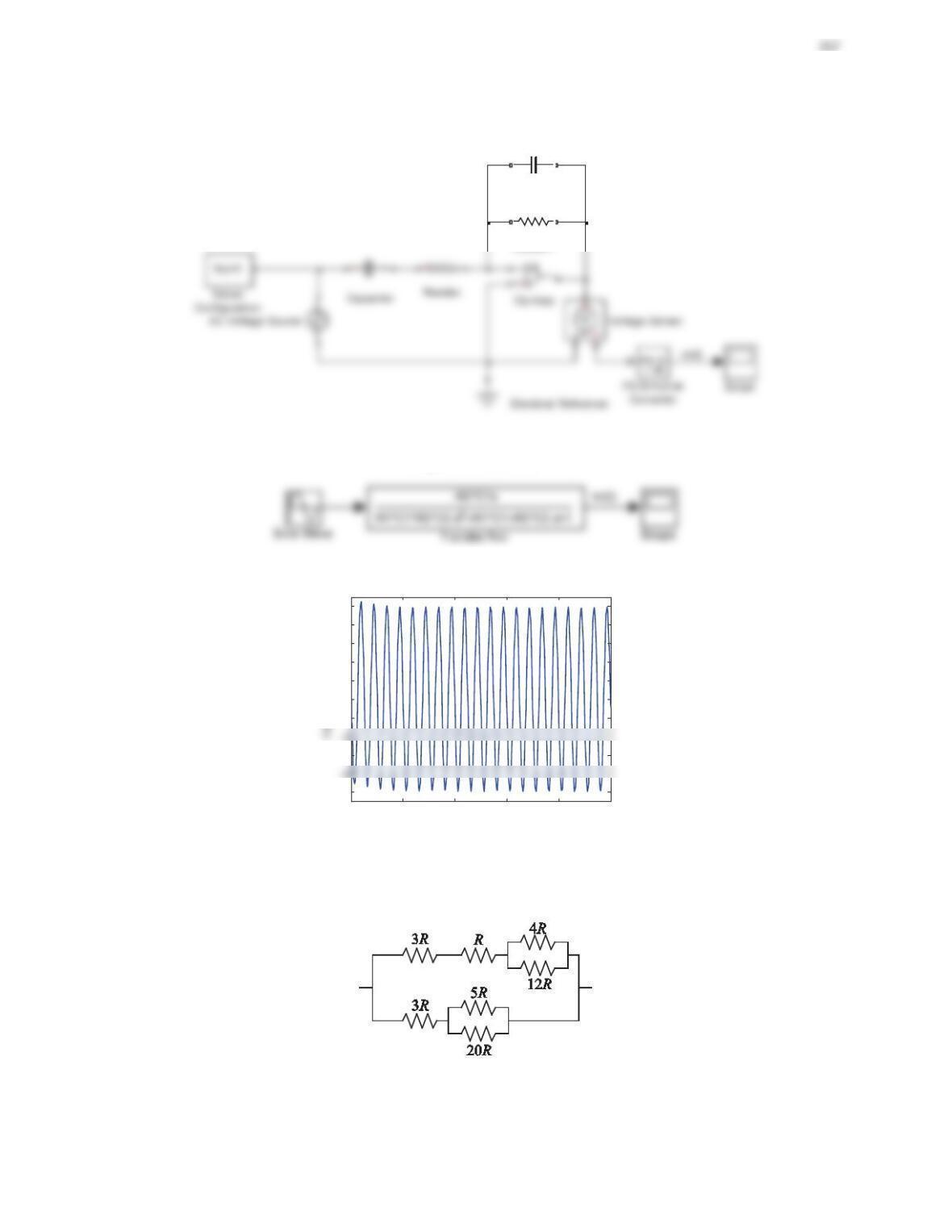
Problem 4
V
+
-
Voltage Sensor
+-
Re si st o r
+-
Inductor
+-
CapacitorAC Voltage Source
00.02 0.04 0.06 0.08 0.1
-1
-0.5
0.5
Time (s)
266
00.02 0.04 0.06 0.08 0.1
-1
-0.5
0.5
1
Time (s)
Frequency = 800 rad/s
00.02 0.04 0.06 0.08 0.1
-1
-0.5
0.5
1
Time (s)
Frequency = 1200 rad/s
Figure PS6-6 No4c
Problem 5
f(x)=0
+-
+
-
+-
Capacitor
Figure PS6-6 No5a
00.1 0.2 0.3 0.4 0.5
0
0.02
0.03
0.05
Time (s)
Output Voltage (V)
Figure PS6-6 No5b
Problem 6
+-
Re si st o r1
+-
Capacitor1
Figure PS6-6 No6a
Figure PS6-6 No6b
00.02 0.04 0.06 0.08 0.1
-10
-6
-2
0
2
4
6
8
10
Time (s)
Figure PS6-6 No6c
Review Problems
1. Determine the equivalent resistance Req for the circuit shown in Figure 6.75.
Figure 6.75 Problem 1.
268
Solution
For the top path, the equivalent resistance for the parallel-connected resistors, 4Rand 12R, is
111
412 3RRR
or 3R
They are connected with the resistor, 3R, in series. Thus, we have
34 7RR R
. The equivalent resistor for the
circuit is
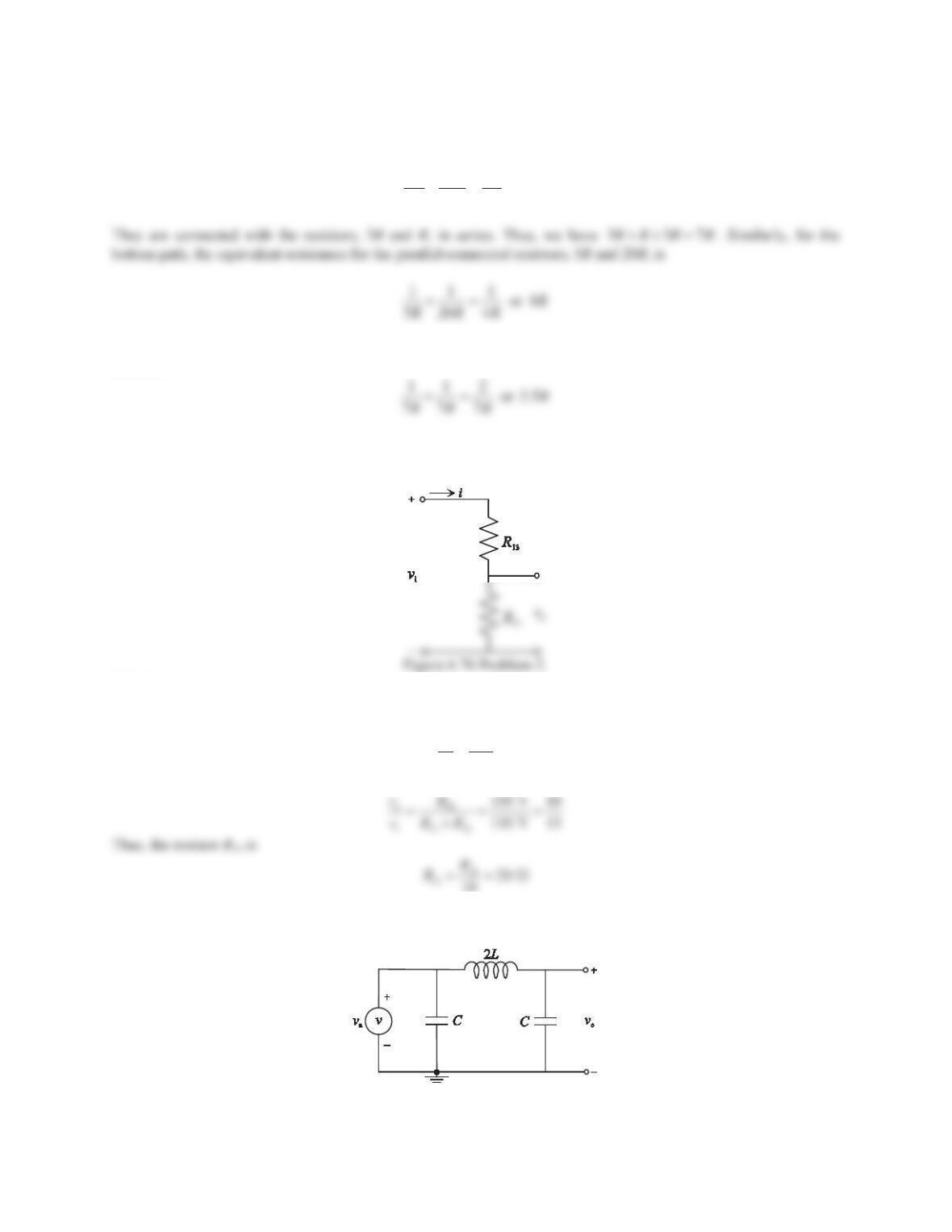
2. Find R13 and R32 for the voltage divider shown in Figure 6.76 so that the current is limited to 0.5 A when vi=
110 V and vo= 100 V.
Solution
The current is 0.5 A and vo= 100 V. Thus, the resistor R32 is
o
32
100 200
0.5
v
R
i
:
For a voltage divider, we have
3. Consider the LC circuit shown in Figure 6.77. Derive the input–output differential equation relating voand va
and find the order of this system.
Figure 6.77 Problem 3.
269
Solution
Denote the voltage at node 1 as v1and the current through the inductor as i. We have
1
1
2di
vL idt
dt C
³
Note that
1a
vv
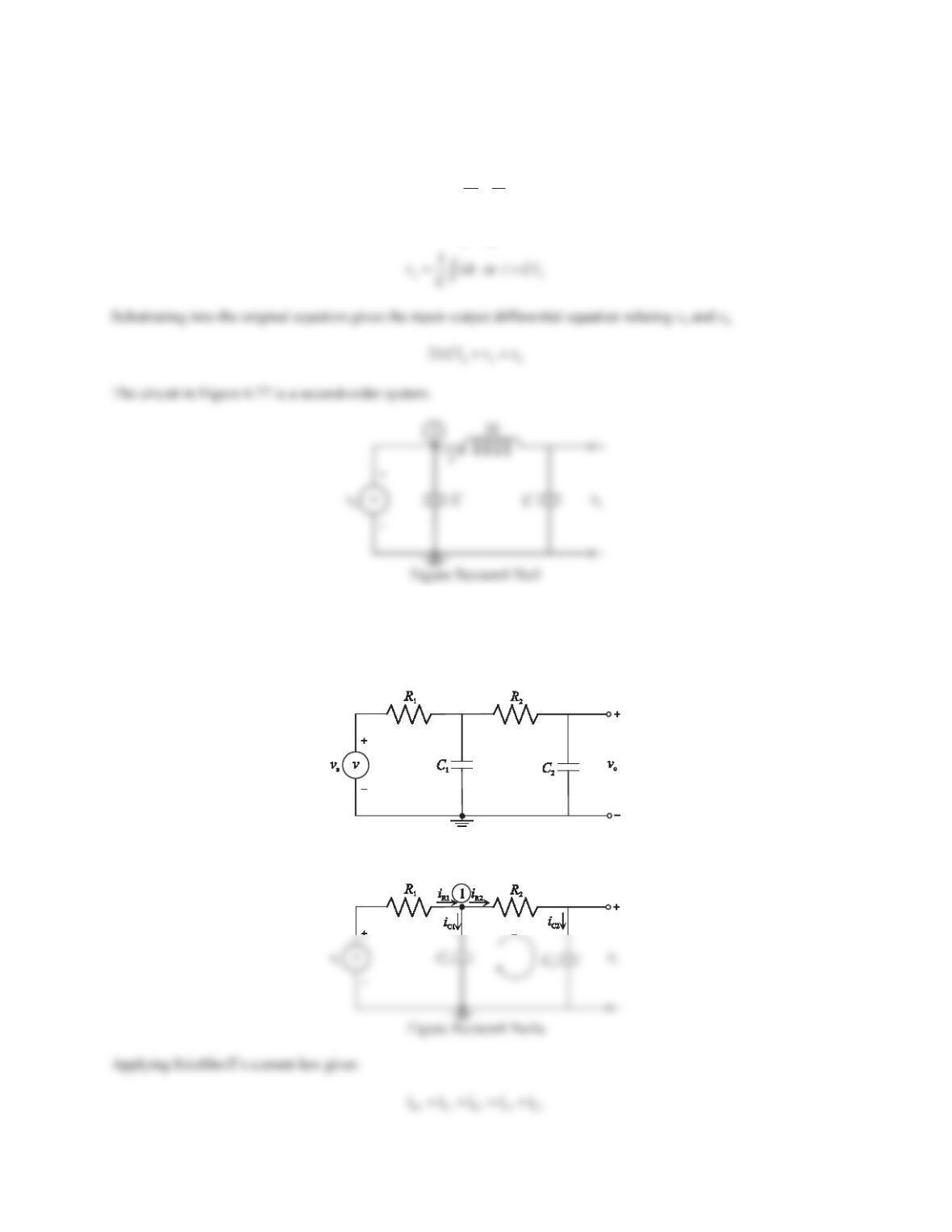
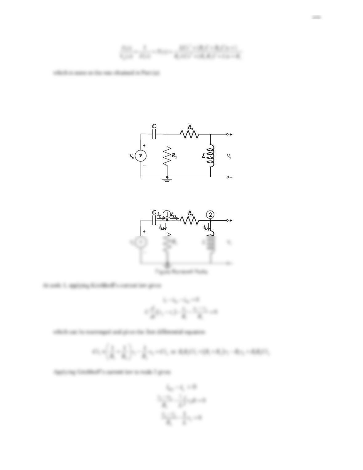
4. Consider the second-order RC circuit shown in Figure 6.78. Assume that all the initial conditions are zero.
a. Use the node or loop method to derive the input–output differential equation relating voand vaand find the
transfer function Vo(s)/Va(s).
b. Use the impedance method to determine the transfer function Vo(s)/Va(s), and compare with the result
obtained in Part (a).
Figure 6.78 Problem 4.
Solution
a. All currents entering or leaving a node are labeled as shown in the figure below.
270
b. Replacing the passive elements with their impedance representations gives the circuit in the sdomain as shown
in the figure below, where
11
ZR
2
1
1
()Zs
Cs
32
2
1
()Zs R
Cs
The impedances Z2and Z3are connected in parallel, and we have
423
111
() () ()Zs Zs Zs
or
22
42
212 1 2
1
() ()
RCs
Zs
RCC s C C s
271
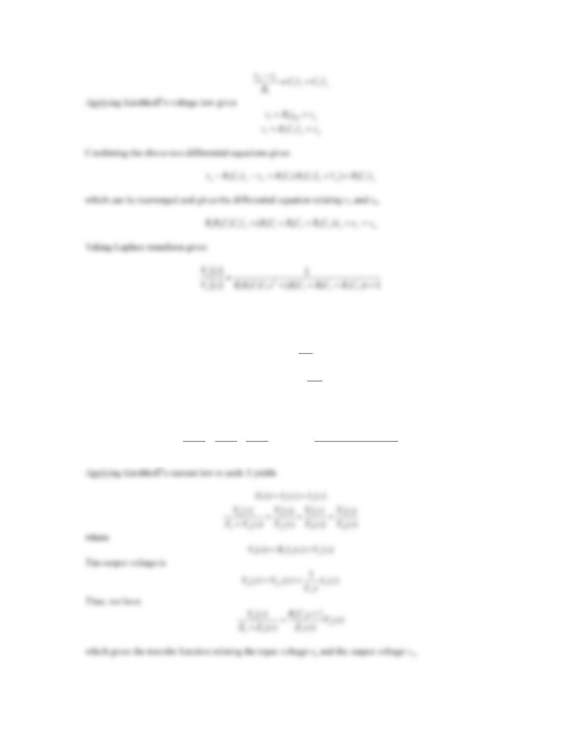
5. Repeat Problem 4 for the RLC circuit shown in Figure 6.79. Assume that all the initial conditions are zero.
a. Use the node or loop method to derive the input–output differential equation relating iand va, and fFind the
transfer function I(s)/Va(s).
b. Use the impedance method to determine the transfer function I(s)/Va(s), and compare with the result
obtained in Part (a).
Figure 6.79 Problem 5.
Solution
a. All currents entering or leaving a node are labeled as shown in the figure below.
272
C1 1 a
1
Ri idt v
C
³
,
2
L2 a
di
Ri L v
dt
which can be written in the s-domain as
b. Replacing the passive elements with their impedance representations gives the circuit in the sdomain as shown
in the figure below, where
1L
()Zs R Ls
and
2C
1
()Zs R
Cs
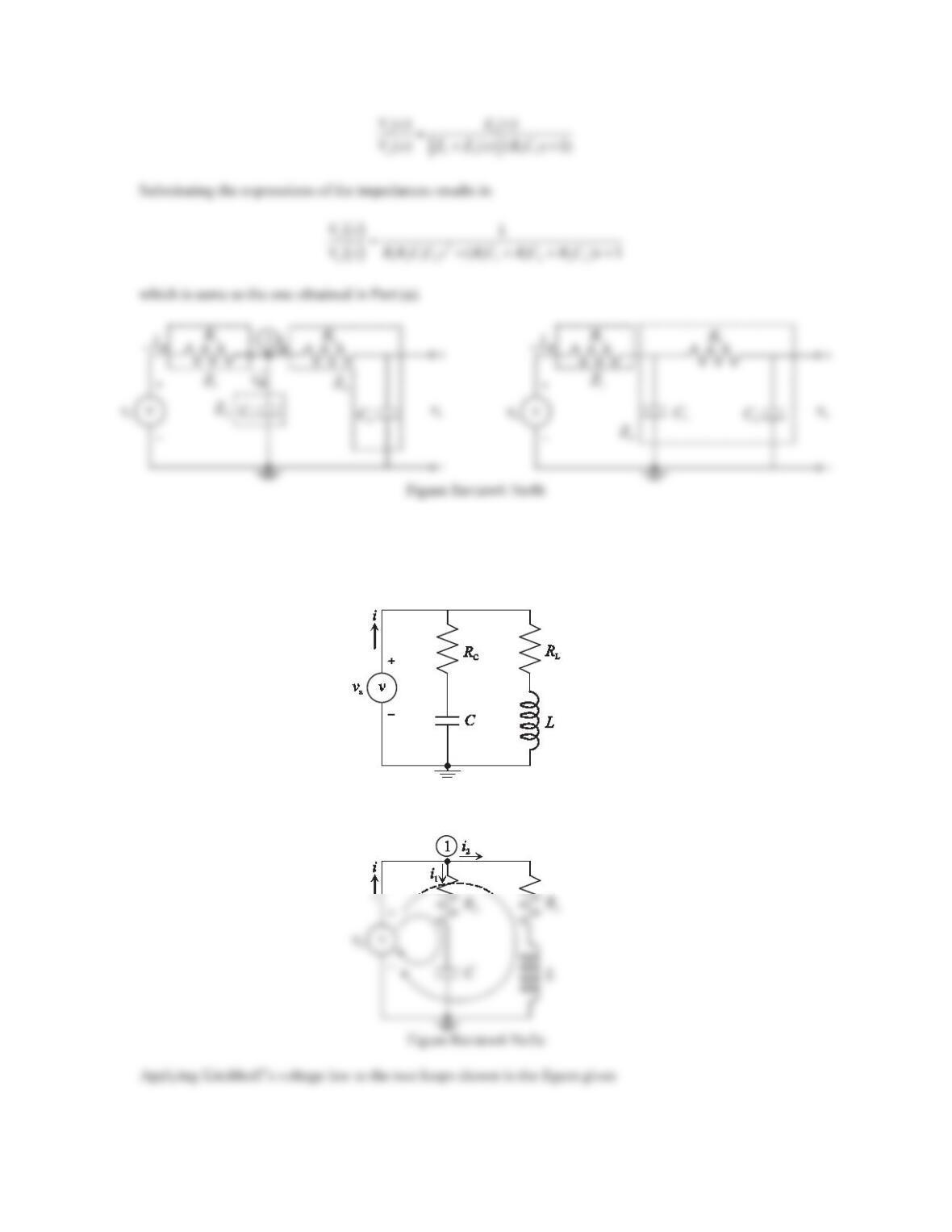
6. Consider the RLC circuit shown in Figure 6.80. Assume that all the initial conditions are zero.
a. Use the node or loop method to derive the input–output differential equation relating voand va, and find the
transfer function Vo(s)/Va(s) directly from the input–output equation.
b. Use the impedance method to determine the transfer function Vo(s)/Va(s), and compare with the result
obtained in Part (a).
Figure 6.80 Problem 6.
Solution
a. All currents entering or leaving node 1 and node 2 are labeled as shown in the figure below.


