SOLUTION
Free Body Diagram. The solution will be very much simplified if one determines
the support reactions first and then considers the equilibrium of two of its three
ΣME=0;
NA(3) –300(4.5) –600(4) =0
Next, write the moment equation of equilibrium about point D for member DBF,
Fig. b.
a+
ΣMD=0;
Bx(1.5) –300(3) =0
Bx=600 N
ΣMB=0;
6–89.
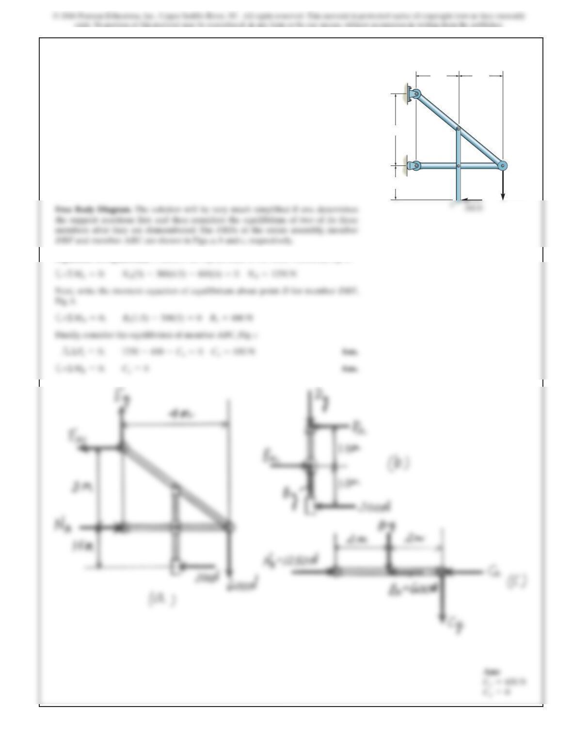
Determine the horizontal and vertical components of force
which pin C exerts on member CDE. The 600-N load is
applied to the pin.
1.5 m
2 m2 m
3 m
A
F
C
D
E
B
600 N
300 N
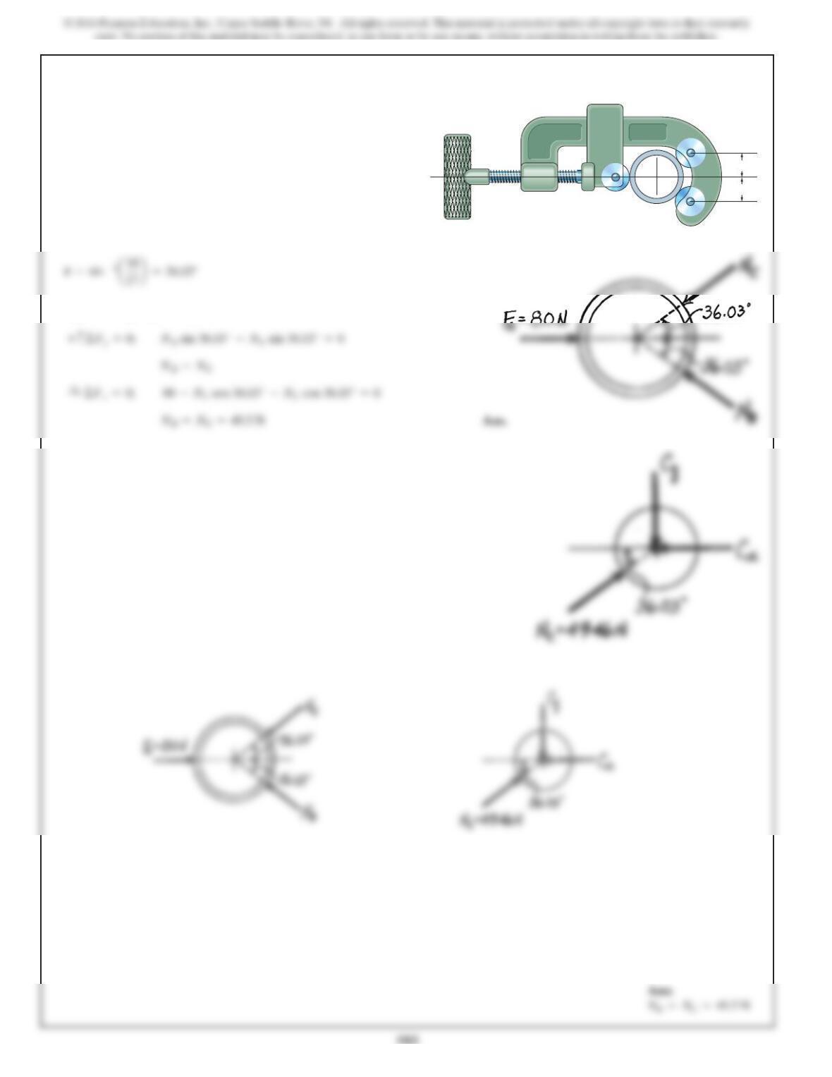
6–90.
The pipe cutter is clamped around the pipe P.If the wheel
at Aexerts a normal force of on the pipe,
determine the normal forces of wheels Band Con
the pipe.The three wheels each have a radius of 7 mm and
the pipe has an outer radius of 10 mm.
F
A
=80 N
10 mm
10 mm
P
C
B
A
SOLUTION
Equations of Equilibrium:
+c©F
y
=0; N
B
sin 36.03° –N
C
sin 36.03° =0
583
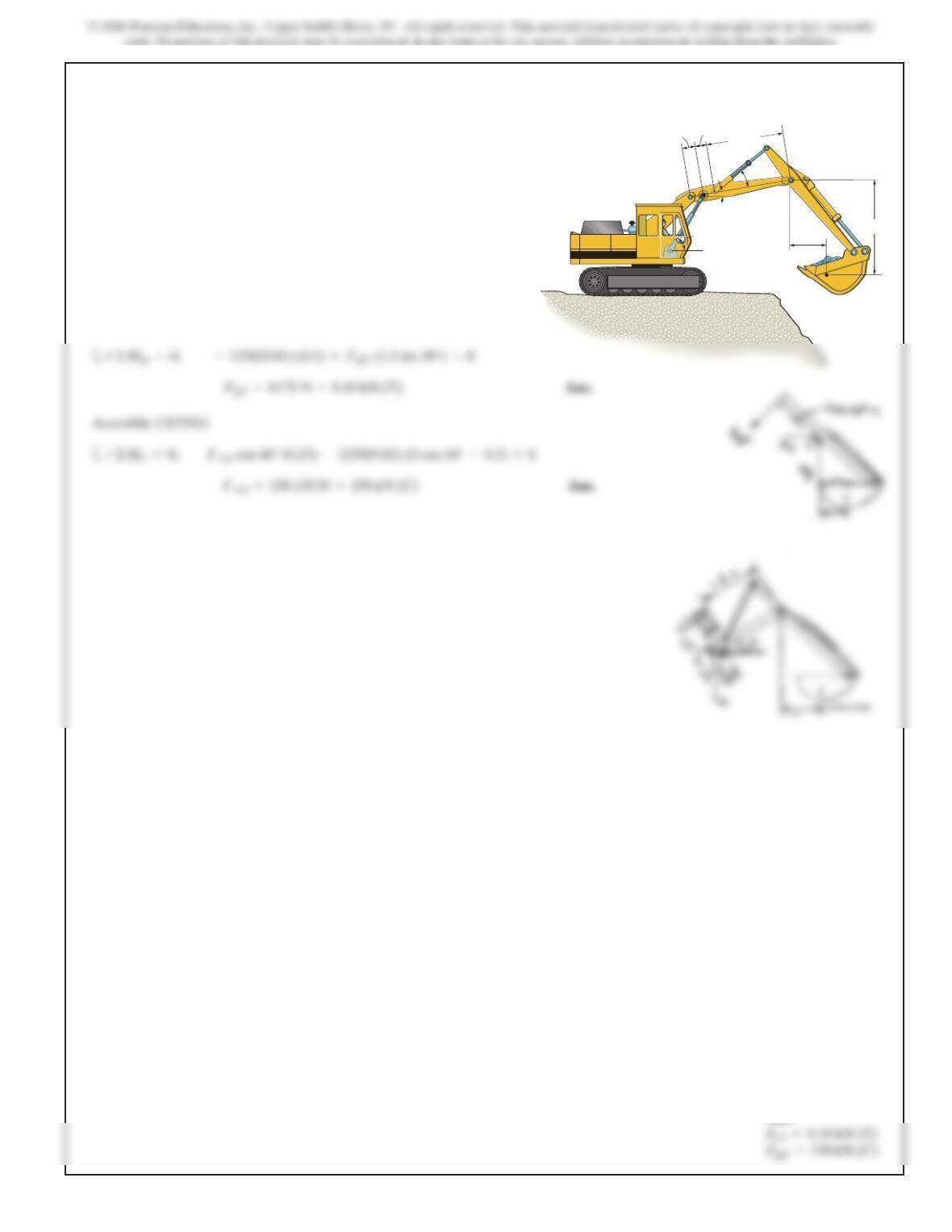
6–91.
Determine the force created in the hydraulic cylinders EF
and AD in order to hold the shovel in equilibrium. The
shovel load has a mass of 1.25 Mg and a center of gravity at
G. All joints are pin connected.
0.5m
0.25 m 0.25 m 1.5m
30fi
10fi
H
G
D
E
C
F
60fi2m
A
SOLUTION
Assembly FHG:
Assembly CEFHG:
Ans:
584
*6–92.
6–93.
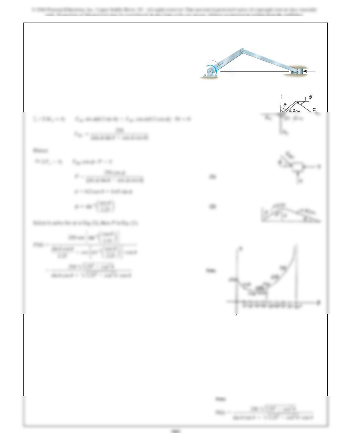
The constant moment of is applied to the crank
shaft. Determine the compressive force Pthat is exerted on
the piston for equilibrium asafunction of Plot the results
of P(ordinate) versus (abscissa) for 0° …u…90°.u
u.
50 N #m
SOLUTION
Member AB:
a
Piston:
Select , solve for in Eq. (2), then Pin Eq. (1).
fu
:
+©Fx=0; FBC cos f–P=0
+©MA=0; FBC sin f(0.2 sin u)+FBC cos f(0.2 cos f)–50 =0
P
0.45 m
0.2m
u
A
B
C
50 N fim
586
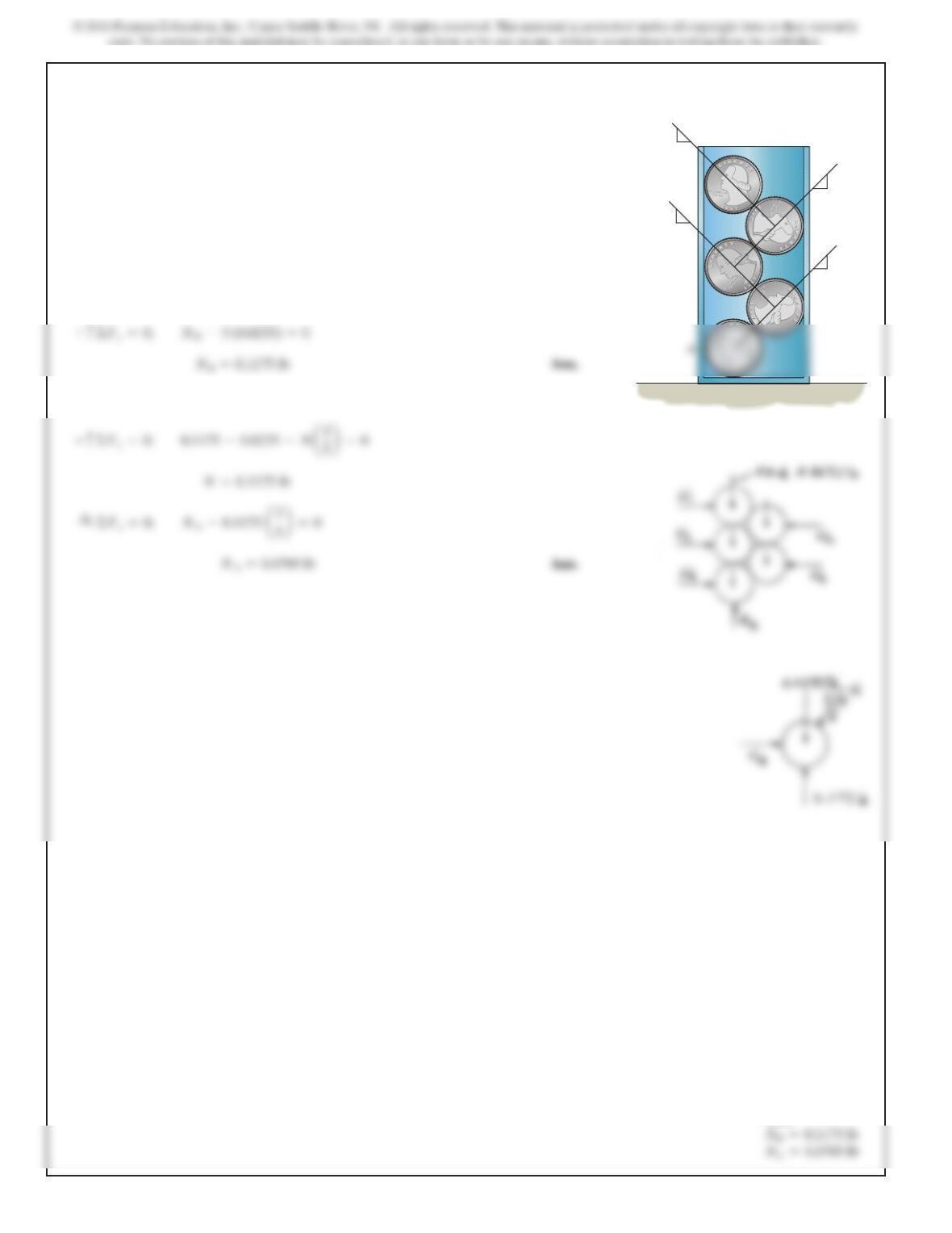
6–94.
Five coins are stacked in the smooth plastic container
shown. If each coin weighs 0.0235 lb, determine the normal
reactions of the bottom coin on the container at points A
and B.
SOLUTION
All coins:
Bottom coin:
3
4
3
3
5
5
5
5
4
4
3
4
B
Ans:
587
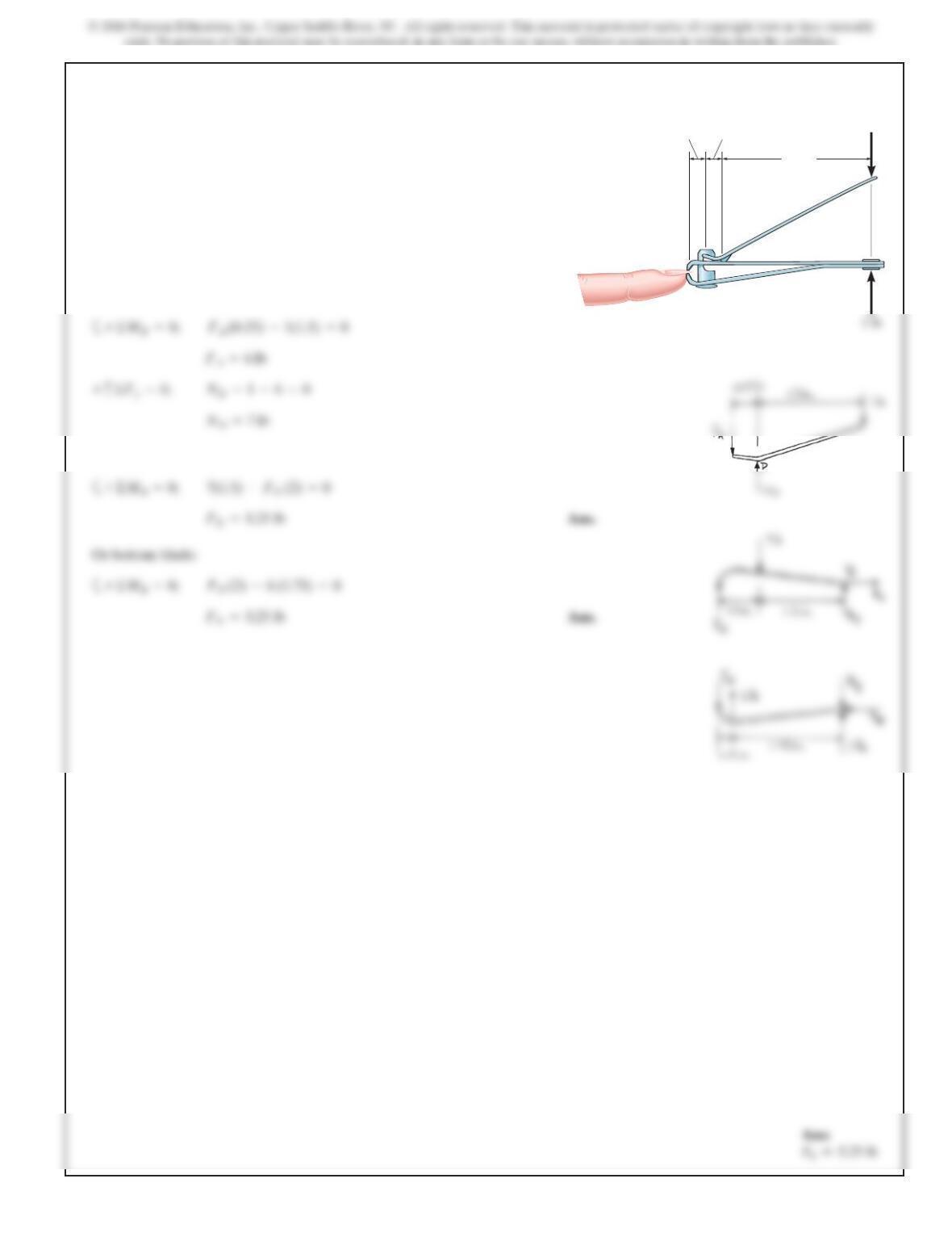
6–95.
The nail cutter consists of the handle and the two cutting
blades. Assuming the blades are pin connected at Band the
surface at Dis smooth, determine the normal force on the
fingernail when a force of 1 lb is applied to the handles as
shown. The pin AC slides through a smooth hole at Aand is
attached to the bottom member at C.
SOLUTION
Handle:
a
Top blade:
a
Or bottom blade:
+©MB=0; 7(1.5) –FN(2) =0
+©MD=0; FA(0.25) –1(1.5) =0
1.5 in.
A
D
C
B
1lb
1lb
0.25in.0.25 in.
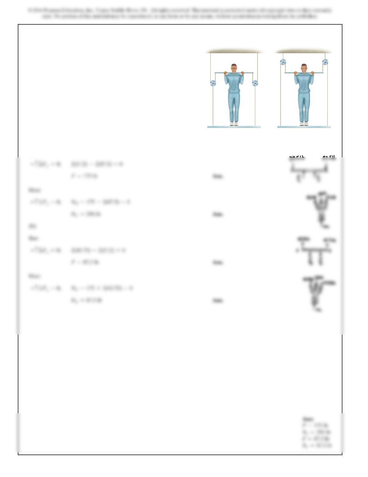
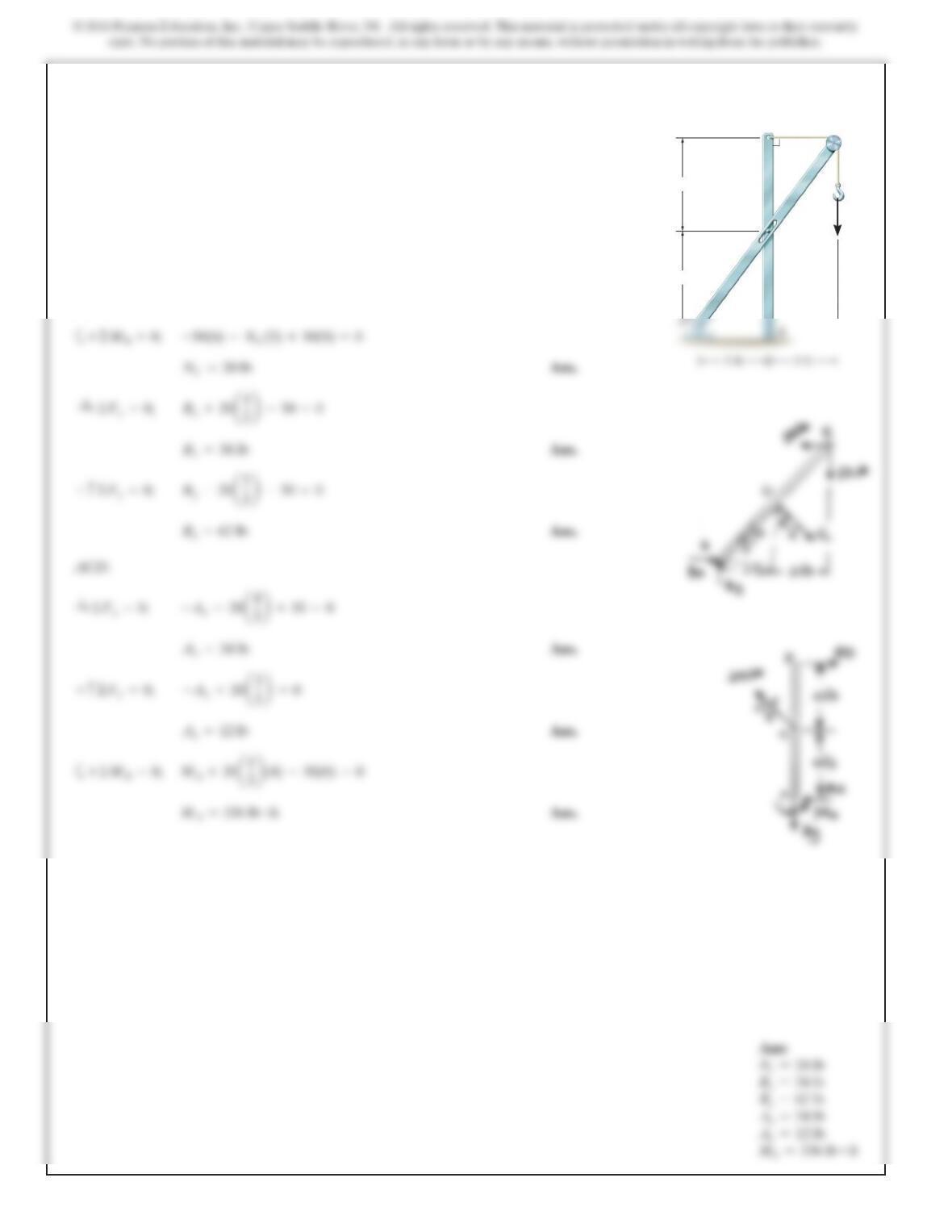
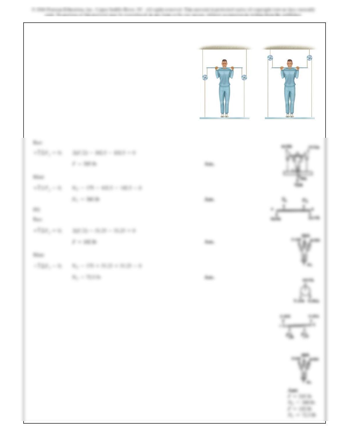
*6–96.
A man having a weight of 175 lb attempts to hold himself
using one of the two methods shown. Determine the total
force he must exert on bar AB in each case and
the normal reaction he exerts on the platform at C.Neglect
the weight of the platform.
CC
AB
AB
(a) (b)
SOLUTION
(a)
Bar:
Man:
(b)
Bar:
F=87.5 lb
589
6–97.
Aman having a weight of 175 lb attempts to hold himself
using one of the two methods shown. Determine the total
force he must exert on bar AB in each case and the normal
reaction he exerts on the platform at C.The platform has a
weight of 30 lb.
CC
AB
AB
(a) (b)
SOLUTION
(a)
Bar:
590
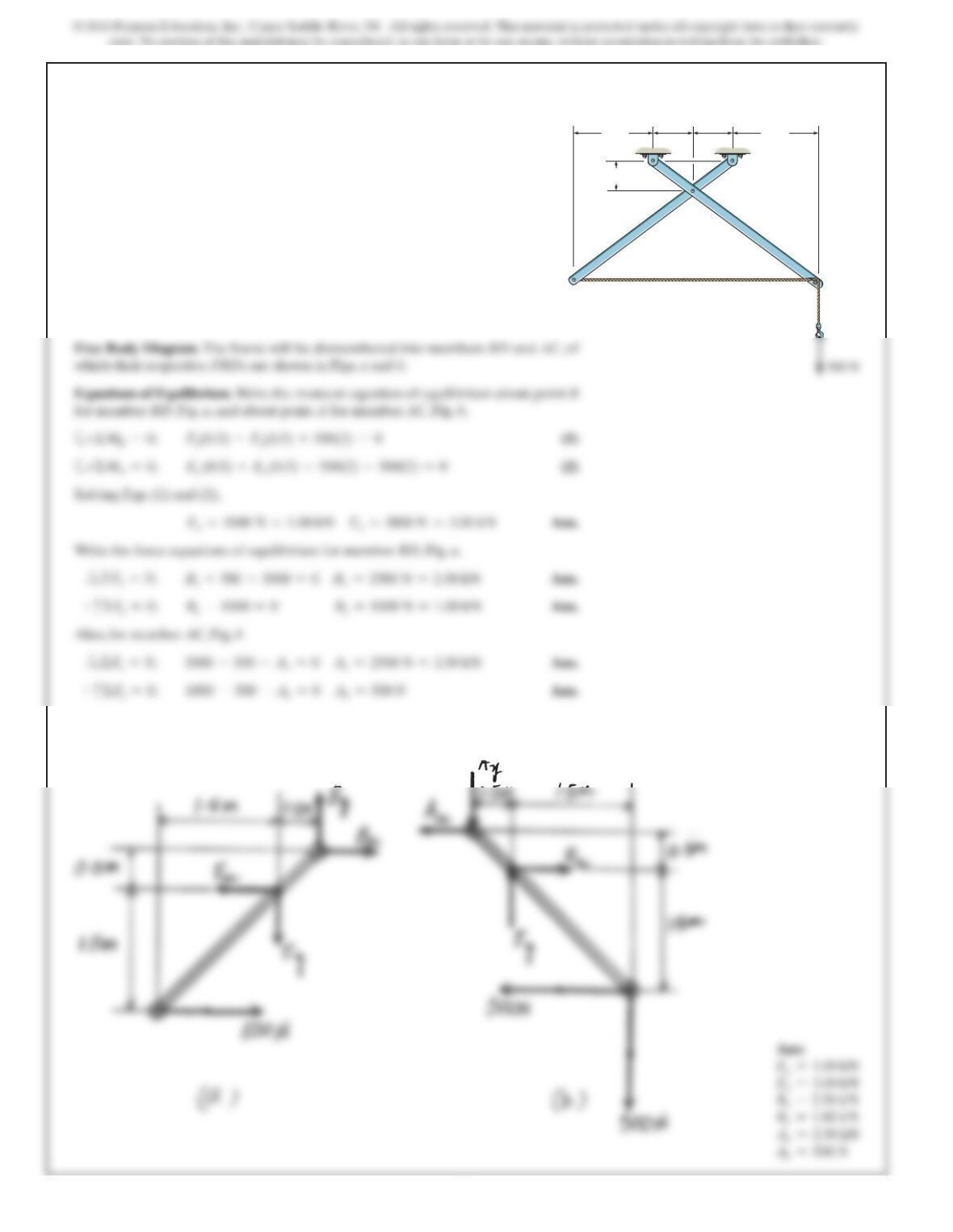
SOLUTION
Free Body Diagram. The frame will be dismembered into members BD and AC, of
which their respective FBDs are shown in Figs. a and b.
6–98.
The two-member frame is pin connected at E. The cable is
attached to D, passes over the smooth peg at C, and supports
the 500-N load. Determine the horizontal and vertical
reactions at each pin. 0.5 m0.5 m
500 N500 N
1 m1 m 1 m1 m
0.5 m0.5 m 0.5 m0.5 m
AA
BB
CC
DD
EE
591
6–99.

*6–100.
Operat
i
on of ex
h
aust an
d
i
nta
k
e va
l
ves
i
n an automo
bil
Ans:
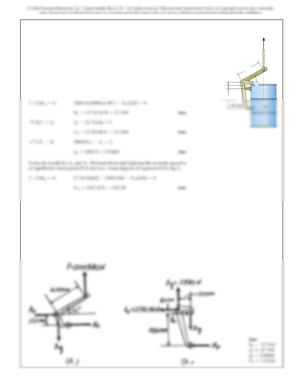
6–101.
If a clamping force of is required at A, determine the
amount of force Fthat must be applied to the handle of the
toggle clamp.
300 N
275 mm
30
30
235 mm
30 mm
30 mm
70 mm
F
C
E
B
D
A
Solving Eqs. (1) and (2) yields
SOLUTION
Equations of Equilibrium:First, we will consider the free-body diagram of the clamp in
Fig.a. Writing the moment equation of equilibrium about point D,
Subsequently, the free – body diagram of the handle in Fig.bwill be considered.
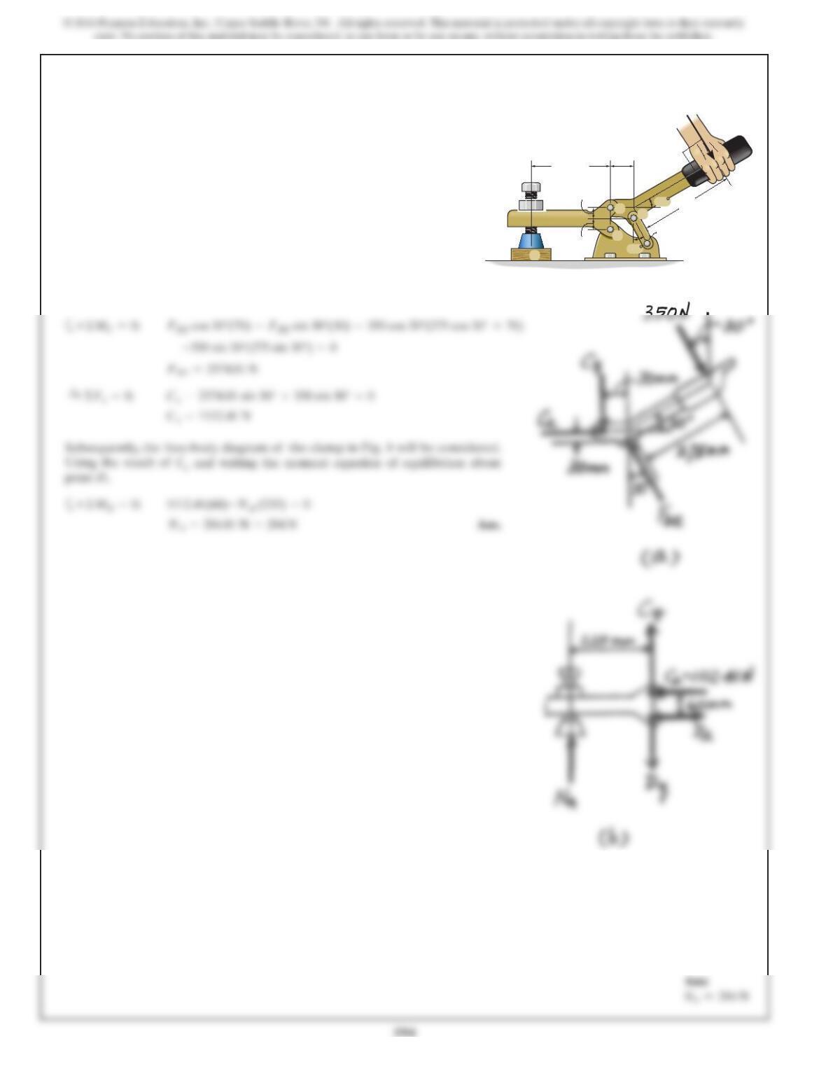
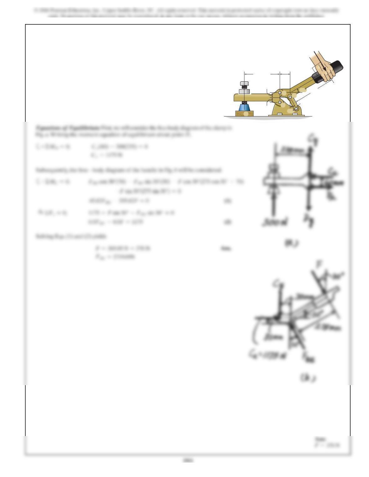
6–102.
If a force of is applied to the handle of the toggle
clamp, determine the resulting clamping force at A.
F
=350 N
275 mm
30
30
235 mm
30 mm
30 mm
70 mm
F
C
E
B
D
A
SOLUTION
Equations of Equilibrium: First, we will consider the free-body diagram of the handle
in Fig. a.
595
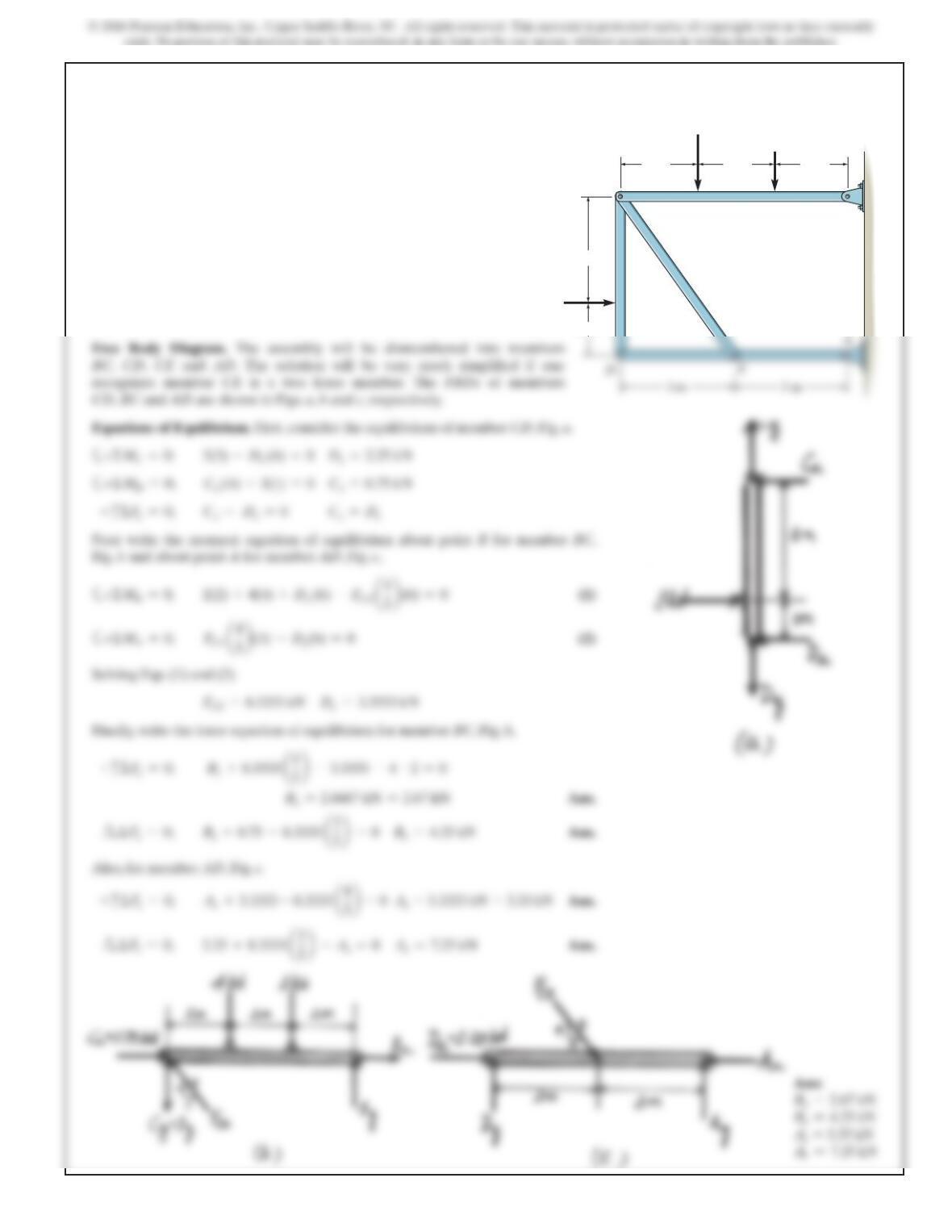
SOLUTION
Free Body Diagram. The assembly will be dismembered into members
BC, CD, CE and AD. The solution will be very much simplified if one
recognizes member CE is a two force member. The FBDs of members
CD, BC and AD are shown in Figs. a, b and c, respectively.
+
c
ΣF
Next write the moment equation of equilibrium about point B for member BC,
Fig.b and about point A for member AD, Fig. c,
Solving Eqs. (1) and (2)
Finally, write the force equation of equilibrium for member BC, Fig. b,
+
c
ΣF
y
=0;
By+8.3333
a
4
–3.3333 –4 –2=0
Also, for member AD, Fig. c.
+
c
ΣF
6–103.
Determine the horizontal and vertical components of force
that the pins at A and B exert on the frame.
2 m
1 m
3 m
3 m
2 m 2 m
3 m
2 kN
3 kN
4 kN
DE
C
A
B