85
18. Electric charge qand electric current
i
are related via /idqdt . In Problem 17, find the transfer function if
()qt
and
()vt
are the system output and input, respectively.
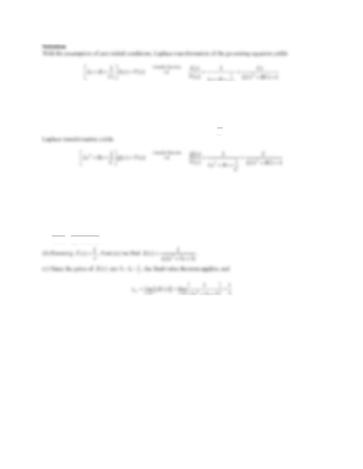
Solution
Noting /idqdt , the governing equation can be rewritten as
1()Lq Rq q v t
C
. With zero initial conditions,
19. The input-output equation for a dynamic system is given as
253 ()xxxft
where
f
and
x
denote the
input and output, respectively.
(a) Find the system’s transfer function.
(b)Assuming ()ft is the unit-step, find the expression for ()Xs using Part (a).
(c) Find the steady-state value ss
xof
()xt
via the final-value theorem.
Solution
(a)
2
() 1
() 253
Xs
Fs ss
253
¯¿
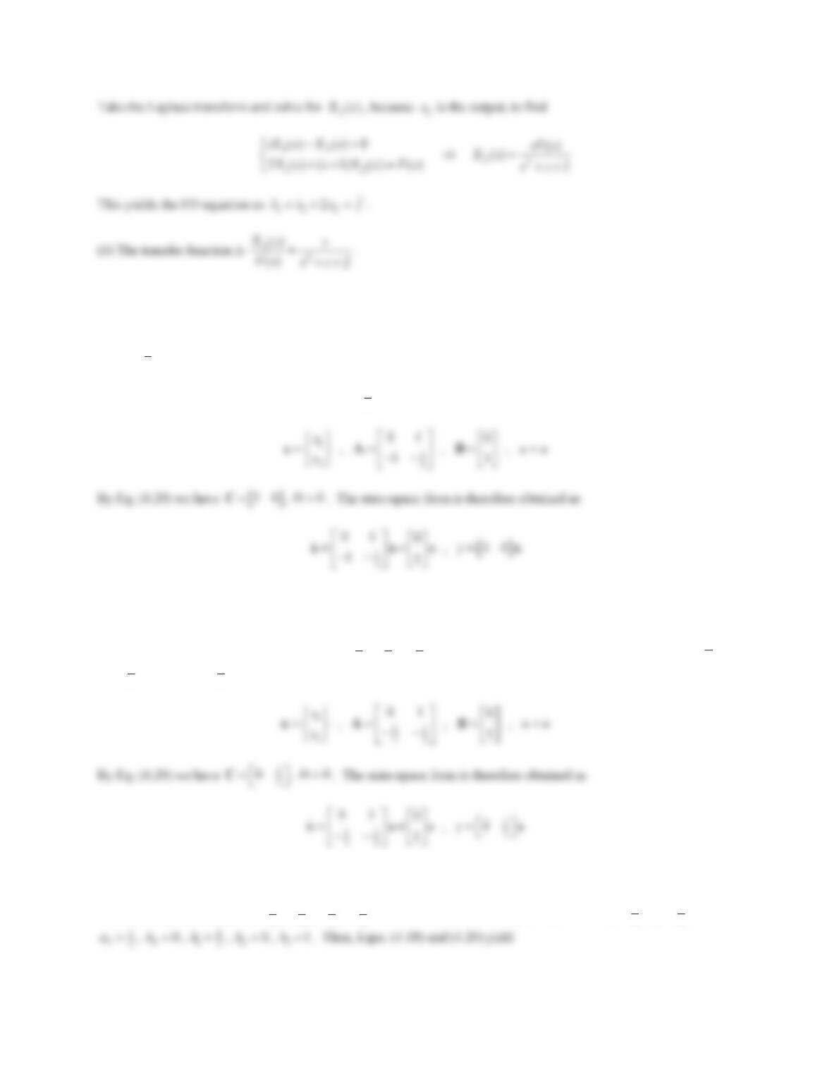
20. The state-space representation of a system model is described as
u
yDu
®
¯
xAxB
Cx
where
>@
1
2
01 0
, , , 0 1 , 0 ,
21 1
xDuf
x
½ ªºªº
®¾ «»«»
¬¼¬¼
¯¿
xA BC
Find
(a) The input-output equation,
(b) The transfer function.
Solution
(a) The state-variable equations are
12
212
2
xx
xxxf
®
¯
86
Problem Set 4.4
In Problem 1–6, find the state-space form directly from the input-output equation.
1.
1
3
3yyyu
Solution
Comparing with Eq. (4.14) we have 2n ,
1
13
a
,21a ,
00b
,10b ,
23b
. By Eq. (4.18),
2.
2yyyu
Solution
Divide by 2 to rewrite in standard form, as
11 1
22 2
yyyu
. Comparing with Eq. (4.14) we find 2n ,
1
12
a
,
1
22
a
,
00b
,
1
12
b
,
20b
. By Eq. (4.18),
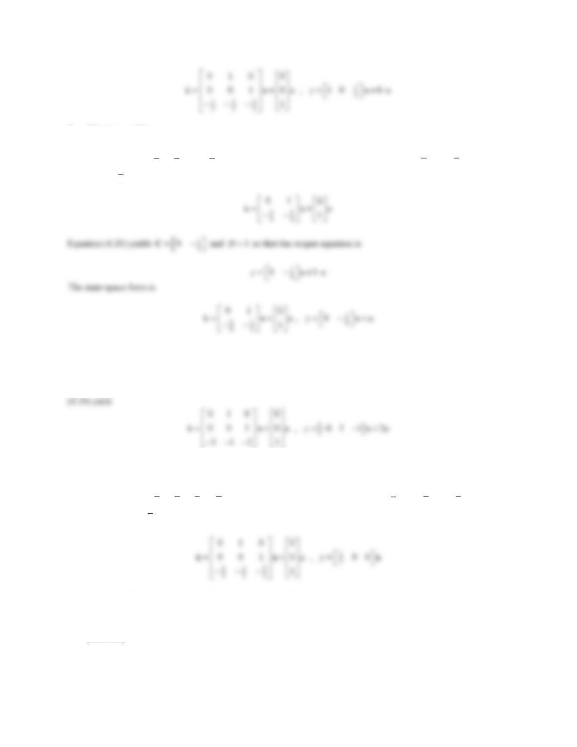
3.
23 2yy yyu u
Solution
Divide through by 2 to get
3
111
222 2
yyyyuu
and compare with Eq. (4.14): 3n ,
1
12
a
,3
22
a ,
87
4.
44yyy uu
Solution
Divide by 4 to get
11 1
44 4
yyyuu
and compare with Eq. (4.14) to deduce 2n ,
1
14
a
,
1
24
a
,
01b
,
10b ,
1
24
b
. The state equation is then obtained as
5.
2323yyyyuu
Solution
Compare with Eq. (4.14): 3n ,
1
2a
,21a ,
33a
,
02b
,10b ,
2
3b
,
30b
. Then, Eqns. (4.18) and
¬¼¬¼
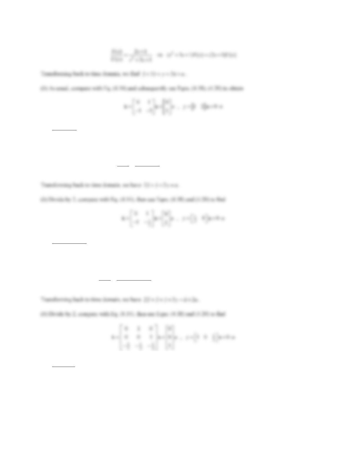
6.
352 2yyyyu
Solution
Divide by 3 to get
521 2
333 3
yyyyu
and compare with Eq. (4.14): 3n ,
5
13
a
,2
23
a ,
1
33
a
,
0
0b
,
10b ,
2
0b
,
2
33
b
. The state-space form is then formed as
In Problems 7–12, given the transfer function
()/ ()Ys Us
,find
(a) The input-output equation.
(b) The state-space form directly from the input-output equation in Part (a).
7.
2
21
31
s
ss
Solution
(a) Using the given transfer function,
88
8.
2
1
22ss
Solution
(a) Using the given transfer function,
2
2
() 1 (2 2) ( ) ( )
() 22
Ys ss YsUs
Us ss
9.
2
32
2
23
s
sss
Solution
(a) Using the given transfer function,
2
32 2
32
() 2 (2 3) ( ) ( 2) ( )
() 23
Ys s sss Ys s Us
Us sss
10.
2
2
1
31
s
ss
Solution
(a) Using the given transfer function,
11.
32
ss
ss
Solution
(a) Using the given transfer function,
12.
2
2
2
1
ss
s
Solution
(a) Using the given transfer function,
2
22
2
() 2 ( 1) ( ) ( 2 ) ( )
() 1
Ys s s sYsssUs
Us s
90
13.
>@
31
3
4
0
01
, , 1 0 , 0
0D
ªº
ªº
«»
«»
¬¼ ¬¼
ABC
Solution
(a) The system is SISO, hence there is only one transfer function. Since
()sG
is
11u
, it is simply denoted by
()Gs
.
With 0D , Eq. (4.21) reduces to
1
() ( )Gs s
CI A B
. Then,
14.
>@
1
2
01 0
, , 0 1 , 0
12D
ªº
ªº
«»
«»
¬¼
¬¼
ABC
Solution
(a) The system is SISO, hence there is only one transfer function. Since
()sG
is
11u
, it is simply denoted by
()Gs
.
With 0D , Eq. (4.21) reduces to
1
() ( )Gs s
CI A B
. Then,
15.
21
33
11
222 2
010 0 100
0 0 1 , 0 , ,
010
u
ªºªº
ªº
«»«»
«»
«»«»
¬¼
«»«»
¬¼¬¼
ABCD0
Solution
(a) The output equation is
23 31 21
u
uu u
yCx D
, hence there are two outputs and one input. Therefore,
()sG
is
21u
. By Eq. (4.21),
¬¼
91
16.
122
2
010 00 100
0 0 1 , 0 , ,
001
123 01
u
ªºªº
ªº
«»«»
«»
«»«»
¬¼
«»«»
¬¼¬¼
ABCD0
Solution
(a) The output equation is
23 31 22 21uu u u
yCx Du
, hence there are two outputs and two inputs. Therefore,
()sG
is
22u
. By Eq. (4.21),
2
¬¼
92
17.12 1
12 2 99 3
33 3
01 0
, , , D
ªºªº
ªº
«»«»
¬¼
¬¼¬¼
ABC
Solution
(a) There is one output and one input, hence
()sG
is
11u
. By Eq. (4.21),
221
199
12
2
99
22
0
323
11
() ( ) 13 3
ss
s
Gs s D s
ªº
ªº
ªº
«»
«»
¬¼
CI A B
18.
>@
01 0
, , 1 2 , 2
23 2 D
ªºªº
«»«»
¬¼¬¼
ABC
Solution
(a) There is one output and one input, hence
()sG
is
11u
. By Eq. (4.21),
In Problems 19–22, given the input-output equation, find
(a) The state-space form.
(b) The transfer function from the state-space form in Part (a).
(c) The transfer function from the given input-output equation and compare with Part (b).
19.
23 3yyyuu
Solution
(a)
>@
01 0
, , 3 1 , 0
32 1 D
ªºªº
«»«»
¬¼¬¼
ABC
20.
22yyuuu
Solution
(a)
>@
01 0
, , 0 1 , 1
20 1 D
ªº ªº
«» «»
¬¼ ¬¼
ABC
21.
22yyyu u
Solution
(a)
311
11 44 2
22
01 0
, , ,
1D
ªº
ªº ªº
«»
«» ¬¼
¬¼
¬¼
ABC
22.
3yyyu u
Solution
(a)
>@
010 0
0 0 1 , 0 , 3 1 0 , 0
10 1 1
D
ªºªº
«»«»
«»«»
«»«»
¬¼¬¼
ABC
23. The state-variable equations and the output equation for a dynamic system are given as
12
12
221
, 2
xx yx x
xxxu
®
¯
Find the transfer function (or transfer matrix) by determining the Laplace transforms of
1
x
and 2
xin the state-
variable equations and using them in the Laplace transform of the output equation.
Solution
Laplace transformation of state-variable equations yields
94
24. Repeat Problem 23 for
12 1
11
221 2
22
,
xx x
xxxu x
½
°
®®¾
°¯¿
¯y
Solution
Laplace transformation of state-variable equations yields
12
11
12
22
( ) ( ) 0
() ( ) () ()
sX s X s
Xs s X s Us
°
®
°
¯
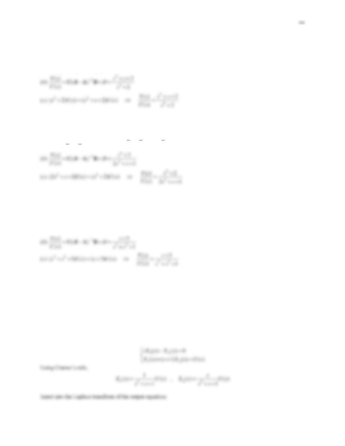
Problem Set 4.5
1. Reduce the block diagram in Figure 4.25 by moving the constant block
K
to the right of the summing junction.
Subsequently, find the transfer function
()/ ()Ys Us
.
Figure 4.25 Problem 1.
Solution
Based on the strategy in Figure 4.15, the block diagram reduces to what is shown in Figure PS4-5 No1. This is a
positive feedback loop, hence
95
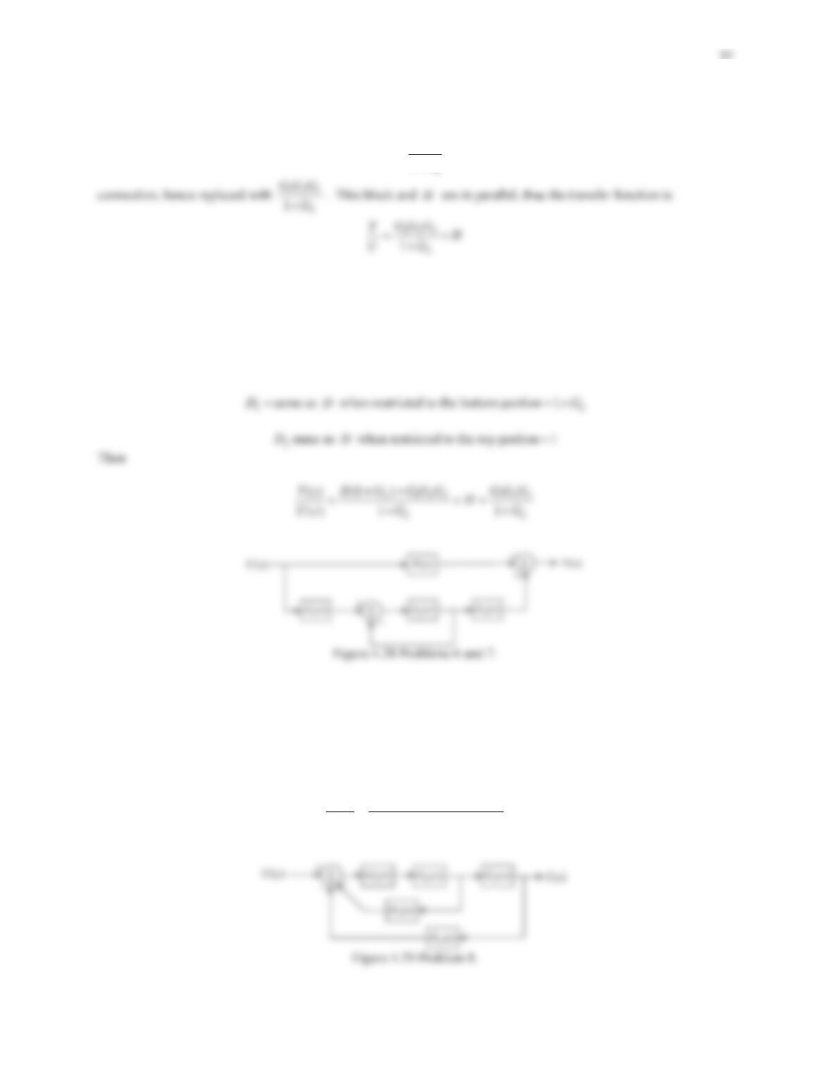
2. For the block diagram in Figure 4.26 find the transfer function
()/ ()Ys Us
using
(a) Block diagram reduction techniques.
(b) Mason’s rule.
Figure 4.26 Problem 2.
Solution
(a) The parallel connection involving
2
G
and
3
G
is replaced with a single block
23
GG
. This block, together with
G
and
G
form a series combination, hence replaced with
>@
GG GG
. This new block and
H
are in a
3. Find the overall transfer function of the block diagram in Figure 4.16, Example 4.21, using Mason’s rule.
Solution
There is one loop with gain
10
3s
and two forward paths with gains
1
(3)ss
and
1
3s
. Since all paths are
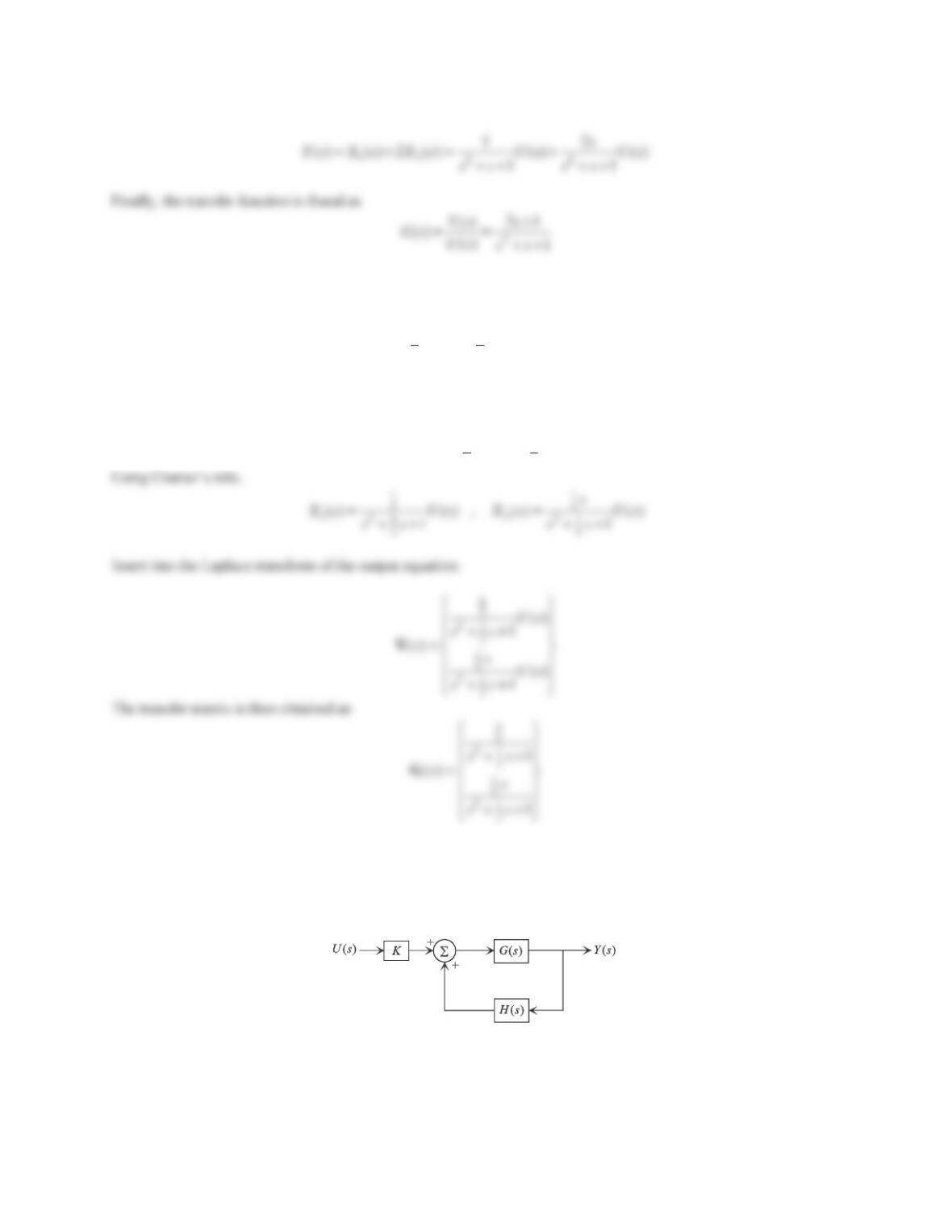
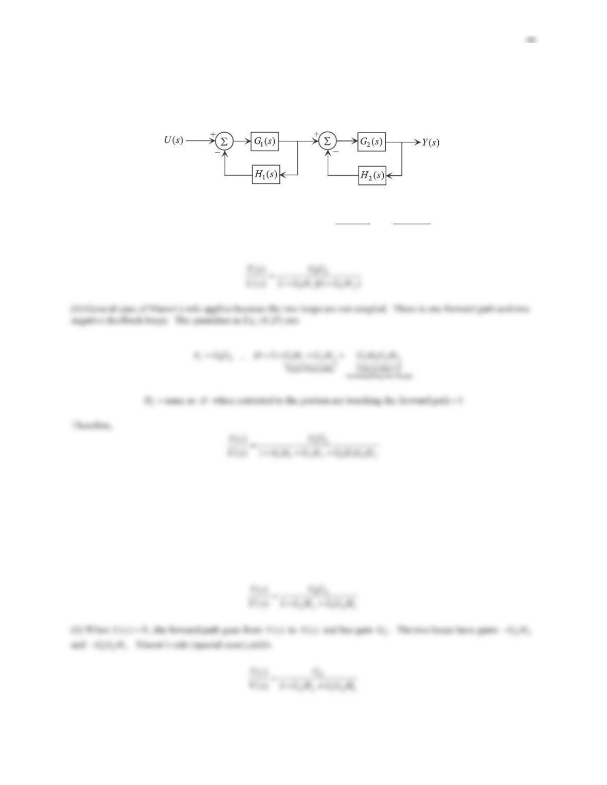
4. Using Mason’s rule find
()/ ()Ys Us
in Figure 4.27.
Solution
There are three loops with gains 11
GH,
12 3
GG H
and 22
GH , as well as one forward path with gain 12
GG .Since
the three loops and the forward path are coupled, the special case of Mason’s rule applies. Therefore,
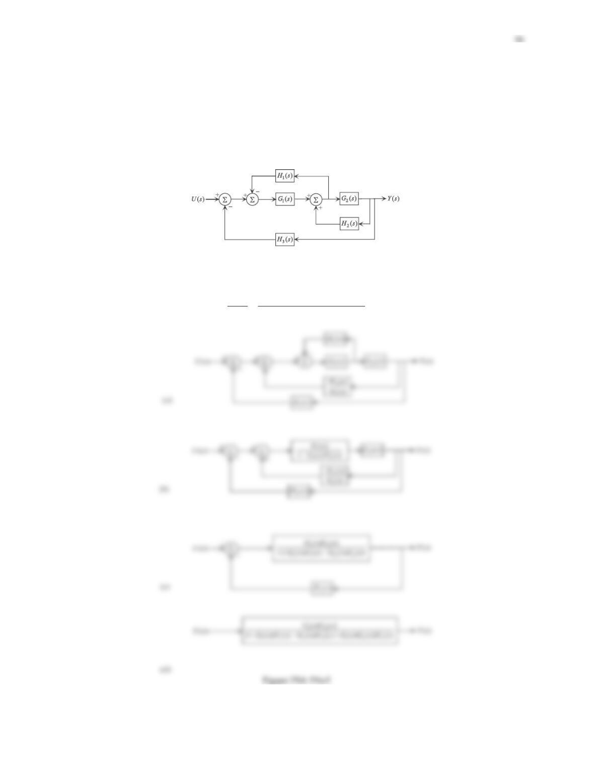
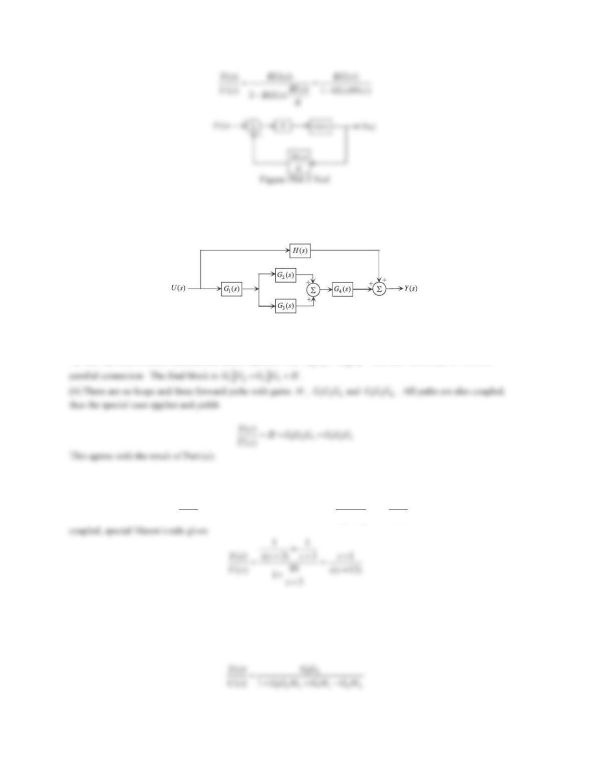
5. Consider the block diagram in Figure 4.27. Use block diagram reduction techniques listed below to find the
overall transfer function.
(i) Move the summing junction of the positive feedback with
2
H
outside of the negative loop containing
1
H
.
(ii) In the ensuing diagram, replace the loop containing 1()Hswith a single block.
(iii) Similarly, replace the two remaining loops with single equivalent blocks to obtain one single block whose input
is
()Us
and whose output is
()Ys
.
Figure 4.27 Problems 4 and 5.
Solution
Details are shown in Figure PS4-5No5. The overall transfer function is readily obtained as
12
11 2 2 12 3
()
() 1
GG
Ys
Us GH GH GGH
6. Using block diagram reduction techniques find
()/ ()Ys Us
in Figure 4.28.
Solution
The negative feedback is replaced with a single block of
2
1
G
G
. This, together with
1
G
and
3
G
form a series
7.Find
()/ ()Ys Us
in Figure 4.28 using Mason’s rule.
Solution
Since not all paths are coupled, general case of Mason’s rule will be applied. There are two forward paths and one
negative feedback loop. The quantities in Eq. (4.25) are:
12123 2
, , 1FH FGGG D G
8. Find the overall transfer function in Figure 4.29 using Mason’s rule.
Solution
There are two loops with gains
12 1
GG H
and
123 2
GG G H
, and one forward path with gain
123
GG G
. All paths are
coupled hence Mason’s rule (special case) applies:
123
12 1 123 2
()
() 1
GG G
Ys
Us GGH GGGH
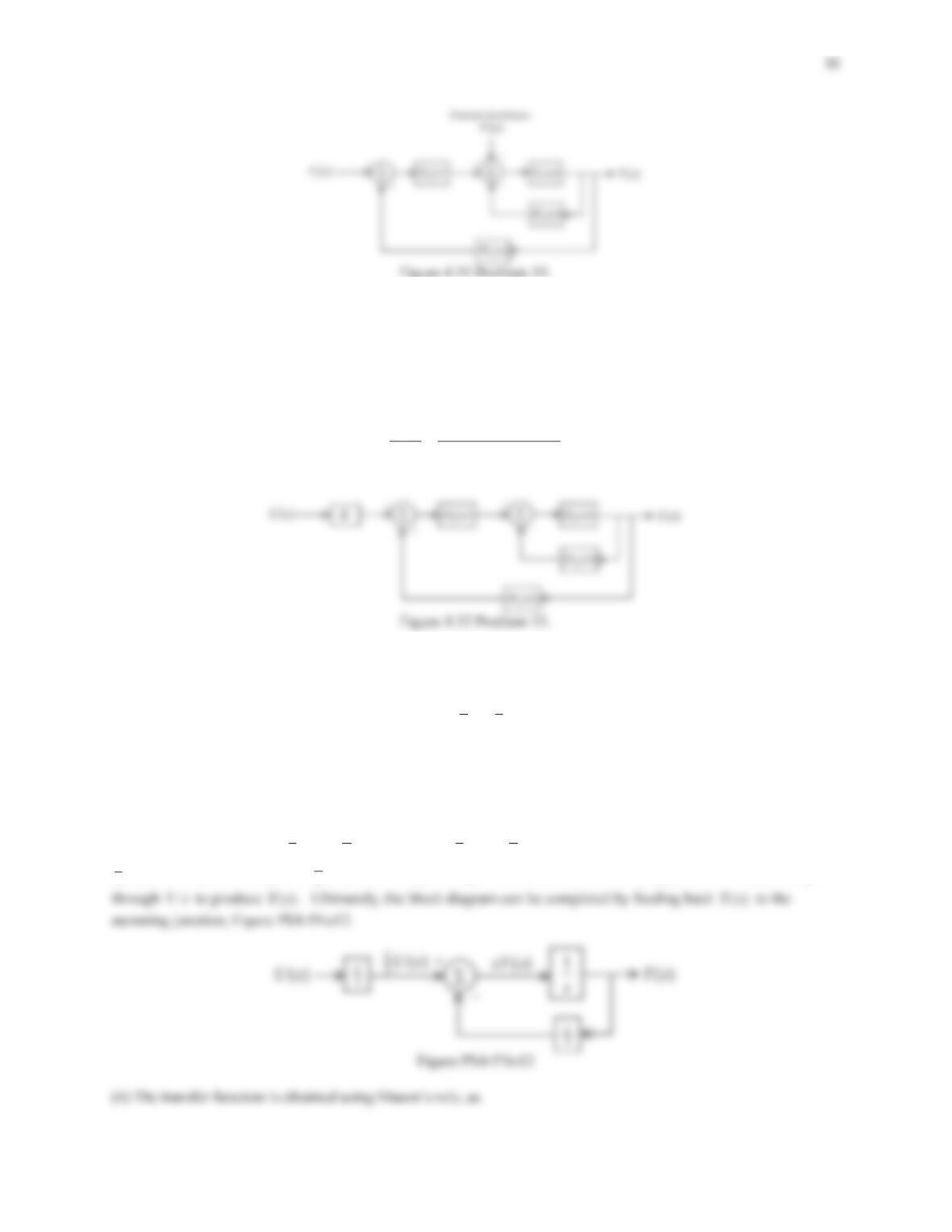
9. For the block diagram in Figure 4.30 find
()/ ()Ys Us
using
(a) Block diagram reduction techniques.
(b) Mason’s rule.
Figure 4.30 Problem 9.
Solution
(a) The two negative loops are replaced with two single blocks of 1
11
1
G
GHand
2
22
1
G
GH
. Since the resulting
blocks are in a series connection, we have
10. Consider the block diagram in Figure 4.31 where
()Vs
represents an external disturbance.
(a) Find the transfer function
()/ ()Ys Us
by setting
() 0Vs
.
(b)Find
()/ ()Ys Vs
by setting
() 0Us
.
Solution
(a) When
() 0Vs
, the forward path going from
()Us
to
()Ys
has a gain of 12
GG , while the two loops have gains
22
GH
and
12 1
GG H
. Using the special case of Mason’s rule,
11. For the block diagram shown in Figure 4.32, where
K
is a constant, obtain the transfer function
()/ ()Ys Us
.
Solution
There is one forward path with gain
12
KG G
and two loops with gains
22
GH
and
12 1
GG H
. Since all paths are
coupled, special case of Mason’s rule yields
12
12 1 2 2
()
() 1
KG G
Ys
Us GGH GH
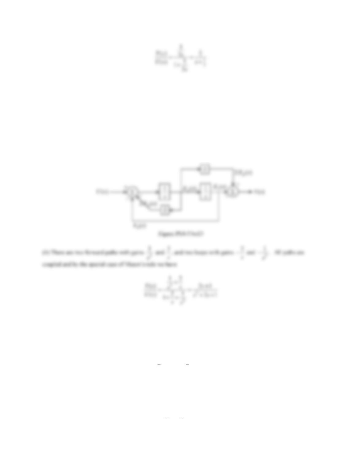
12. The input-output equation for a SISO system is described by
11
23
yyu
(a) Construct a block diagram containing a feedback loop.
(b) Find the transfer function
()/ ()Ys Us
directly from the block diagram.
Solution
(a) The input
()Us
must appear on the far left, and the output
()Ys
on the far right. Laplace transformation of the
I/O equation yields
11
32
() () ()sY s U s Y s
. The term 11
32
() ()Us Ysrequires a summing junction with inputs
1
3
()Us
with a positive sign and
1
2()Ys
with a negative sign. The output of the summing junction,
()sY s
, then goes
100
13. The state-variable equations and output equation of a system are given as
12
12
212
, 2
2
xx yx x
xxxu
®
¯
where
u
and
y
are the input and output, respectively.
(a) Build the block diagram.
(b) Find the transfer function
()/ ()Ys Us
directly from the block diagram.
Solution
(a) Details are shown in Figure PS4-5No13.
14. The state-space representation of a system model is given as
u
yDu
®
¯
xAxB
Cx
with
>@
1
11
233
01 0
, , , 1 1 , 0 ,
1
xDuu
x
ªº ªº
½
®¾ «» «»
¯¿ ¬¼ ¬¼
xA BC
(a) Build the block diagram.
(b) Find the transfer function directly from the block diagram.
Solution
(a) The state-space form reveals the following information:
12
12
11
212
33
,
xx yx x
xxxu
°
®
°
¯
101
Proceeding as always, the block diagram is constructed and shown in Figure PS4-5No14.
In problems 15–18 the system’s input-output equation is provided.
(a) Find the state-variable equations and the output equation.
(b) Construct the block diagram based on the information in Part (a).
(c) Determine the transfer function directly from the block diagram in Part (b).
15.
23yyyu
Solution
(a) With
1
xy
and 2
xy we find
>@
12
2
1
212
2
,
3
xx yx
xxxu
°
®
°
¯
ss
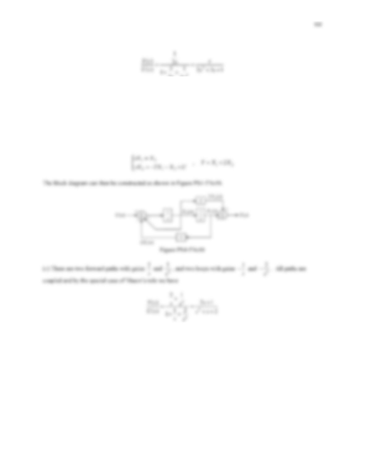
16.
22yy y uu
Solution
(a) With
1
xy
and 2
xy we find
12
12
212
, 2
2
xx yx x
xxxu
®
¯
(b) Laplace transformation yields
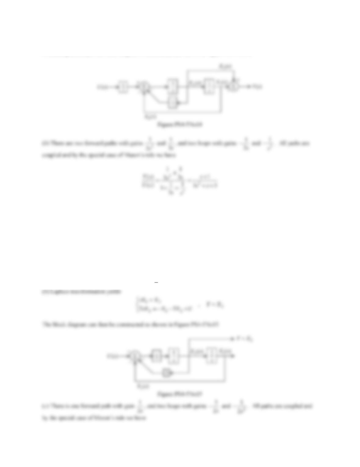
17.
2yyyuu
Solution
(a) With
1
xy
,2
xy and
3
xy
, we find
12
23 23
331
,
2
xx
xx yxx
xxxu
°
®
°
¯
(b) Laplace transformation yields
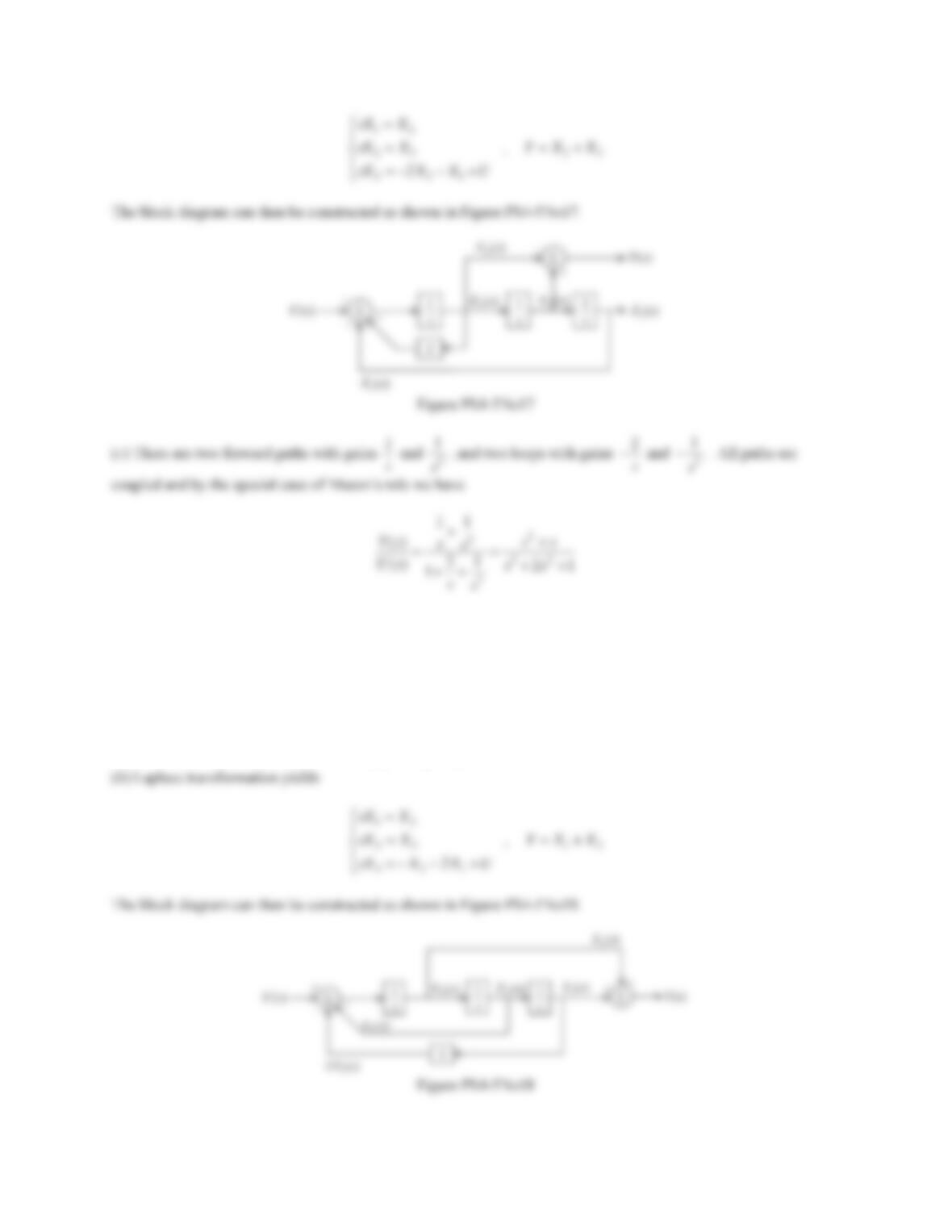
103
18.
2yy yuu
Solution
(a) With
1
xy
,2
xy and
3
xy
, we find
12
23 13
321
,
2
xx
xx yxx
xxxu
°
®
°
¯
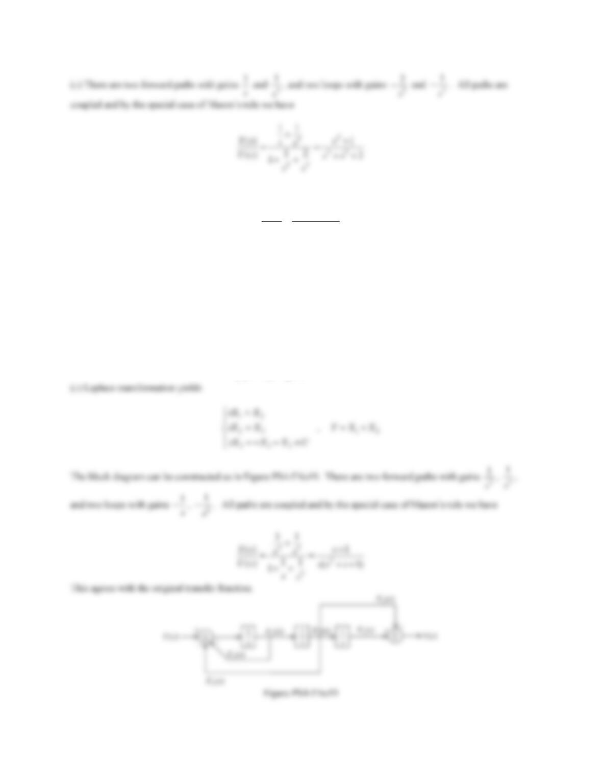
104
19. A system is described by its transfer function
2
() 1
() (1)
Ys s
Us ss s
(a) Find the input-output equation.
(b) Find the state-space form from the input-output equation.
(c) Build a block diagram based on the information in Part (b). Find the transfer function directly from the block
diagram and compare with the given transfer function.
Solution
(a) The input-output equation is derived as
yyyuu
.
(b) With
1
xy
,2
xy and
3
xy
, we find
12
23 12
332
,
xx
xx yxx
xxxu
°
®
°
¯