Problem 8.17
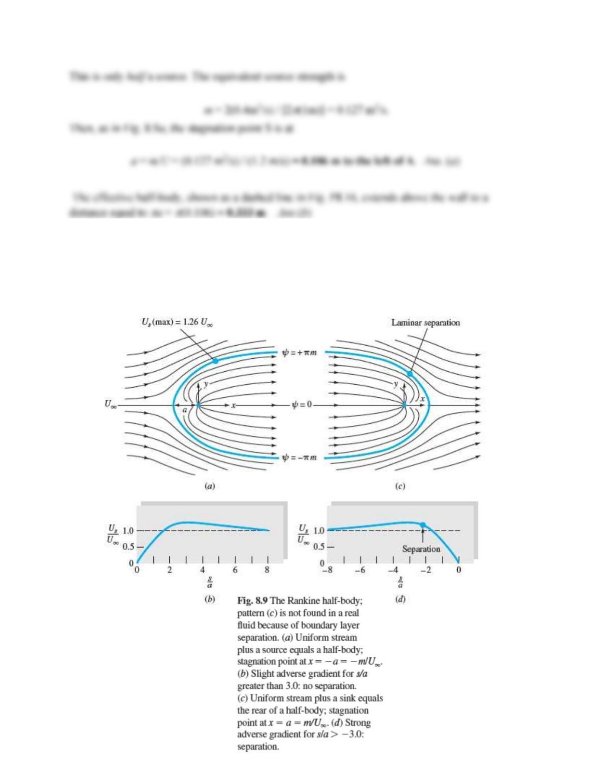
Find the position (x, y) on the upper surface of the half-body in Fig. 8.9a for which the local velocity
equals the uniform stream velocity. What should the pressure be at this point?
Solution 8.17
The surface velocity and surface contour are given by Eq. (8.18):
Problem 8.18
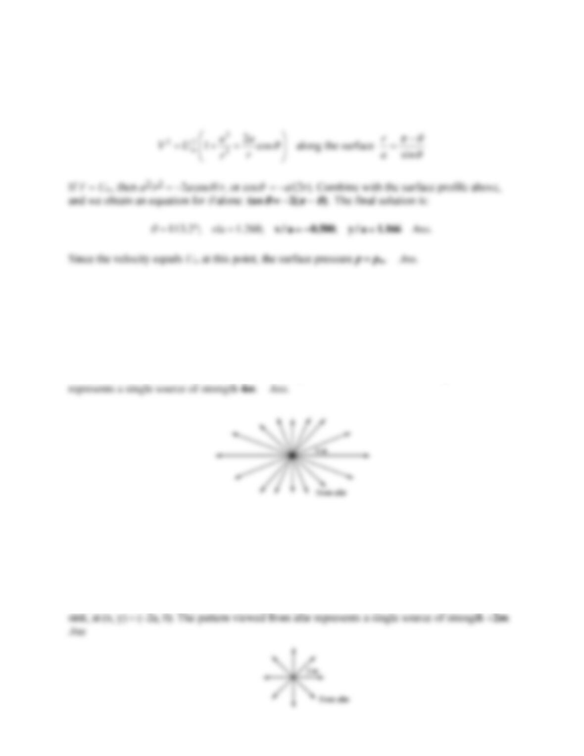
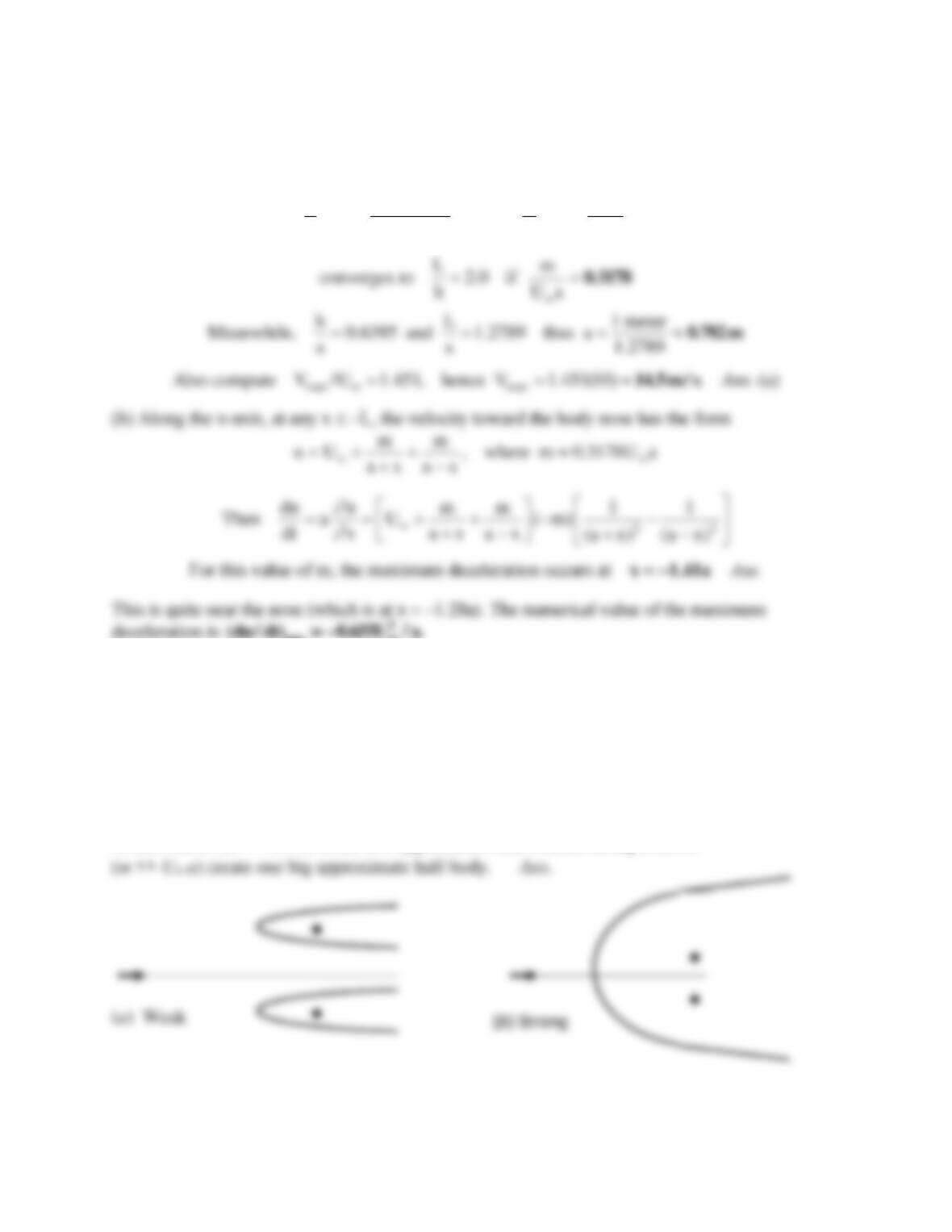
Plot the streamlines and potential lines of the flow due to a line source of strength m at (a, 0) plus
a line source 3m at (–a, 0). What is the flow pattern viewed from afar?
Solution 8.18
The pattern viewed close-up is shown above. The pattern viewed from afar is at right and
Problem 8.19
Plot the streamlines and potential lines of the flow due to a line source of strength 3m at (a, 0)
plus a sink –m at (–a, 0). What is the pattern viewed from afar?
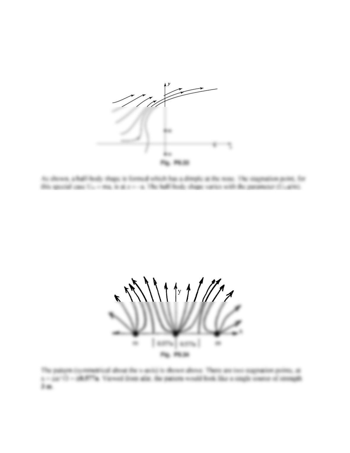
Solution 8.19
The pattern viewed close-up is shown at upper right—there is a stagnation point to the left of the
Problem 8.20
Plot the streamlines of the flow due to a line vortex +K at (0, +a) and a line vortex –K at (0, –a).
What is the pattern viewed from afar?
Solution 8.20
The pattern viewed close–up is shown below (see Fig. 8.17b of the text). The pattern viewed
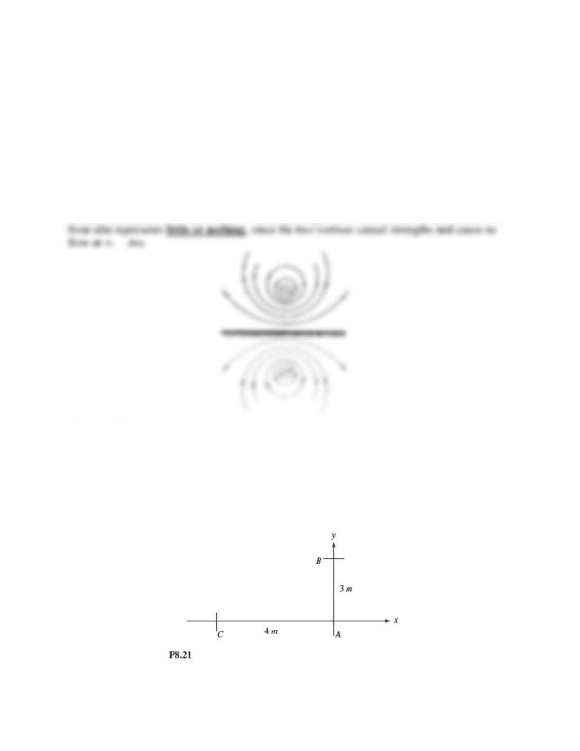
Problem 8.21
At point A in Fig. P8.21 is a clockwise line vortex of strength K = 12 m2/s. At point B is a line
source of strength m = 25 m2/s. Determine the resultant velocity induced by these two at point C
Plot the streamlines of the flow due to a line vortex +K at (0, +a) and a line vortex –K at (0, –a).
What is the pattern viewed from afar?
Solution 8.21
The vortex induces a velocity K/rAC = (12m2/s)/4m =
Problem 8.22
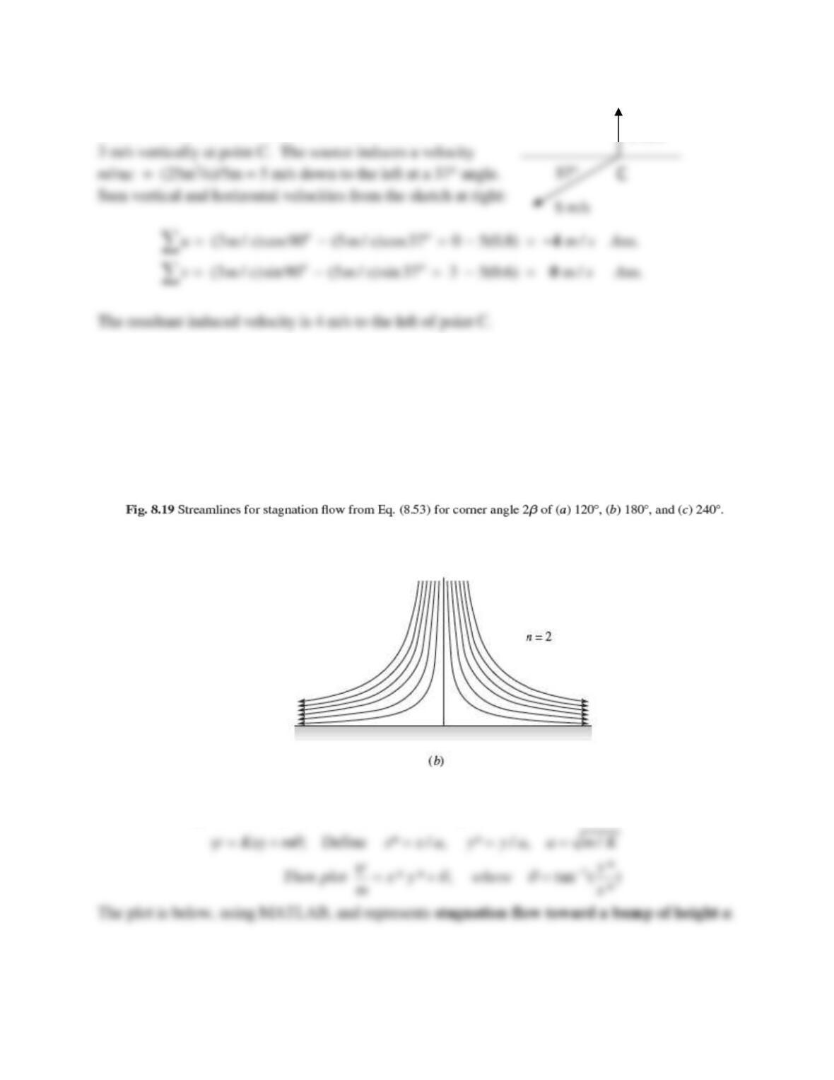
Consider inviscid stagnation flow,
= Kxy (see Fig. 8.19b), Superimposed with a source at the
origin of strength m. Plot the resulting streamlines in the upper half plane, using the length scale
a = (m/K)1/2. Give a physical explanation of the flow pattern.
Solution 8.22
The sum of stagnation flow plus a line source at the origin is
3 m/s
Problem 8.23
Sources of strength m = 10 m2/s are placed at points A and B in Fig. P8.23. At what height h
should source B be placed so that the net induced horizontal velocity component at the origin is
8 m/s to the left?
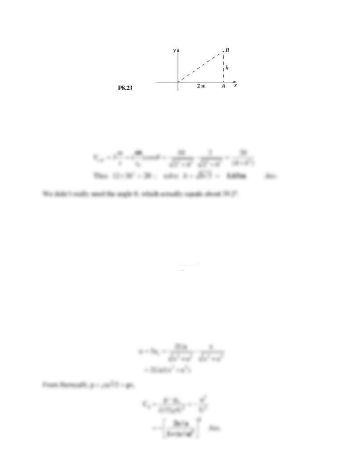
Solution 8.23
Check the velocity induced at the origin by source A: VA = 10 m2/s/2m = 5 m/s to the left. Thus
source B only needs to contribute 8 – 5 = 3 m/s to the left:
Problem 8.24
Line sources of equal strength m = Ua, where U is a reference velocity, are placed at (x, y) = (0, a)
and (0, –a). Sketch the stream and potential lines in the upper half plane. Is y = 0 a “wall”? If so,
sketch the pressure coefficient
0
2
1
2
p
pp
CU
−
=
along the wall, where po is the pressure at (0, 0). Find the minimum pressure point and indicate where
flow separation might occur in the boundary layer.
Solution 8.24
This problem is an “image” flow and is sketched in Fig. 8.17a of the text. Clearly y = 0 is a
“wall” where
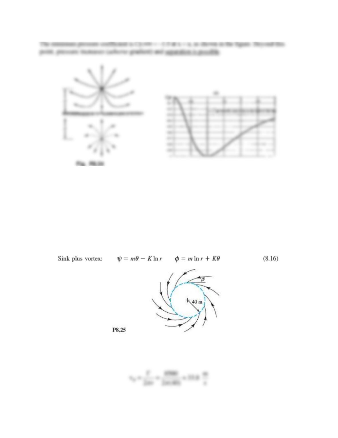
Problem 8.25
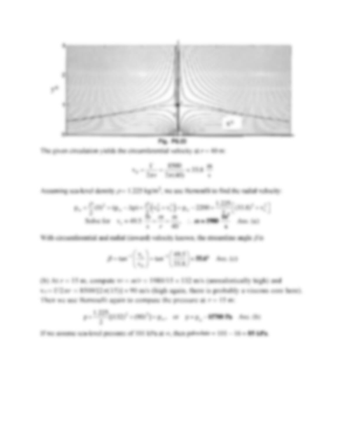
Let the vortex/sink flow of Eq. (8.16) simulate a tornado as in Fig. P8.25. Suppose that the
circulation about the tornado is = 8500 m2/s and that the pressure at r = 40 m is 2200 Pa less
than the far-field pressure. Assuming inviscid flow at sea-level density, estimate (a) the appropriate
sink strength –m, (b) the pressure at r = 15 m, and (c) the angle
at which the streamlines cross
the circle at r = 40 m (see Fig. P8.25).
Solution 8.25
The given circulation yields the circumferential velocity at r = 40 m:
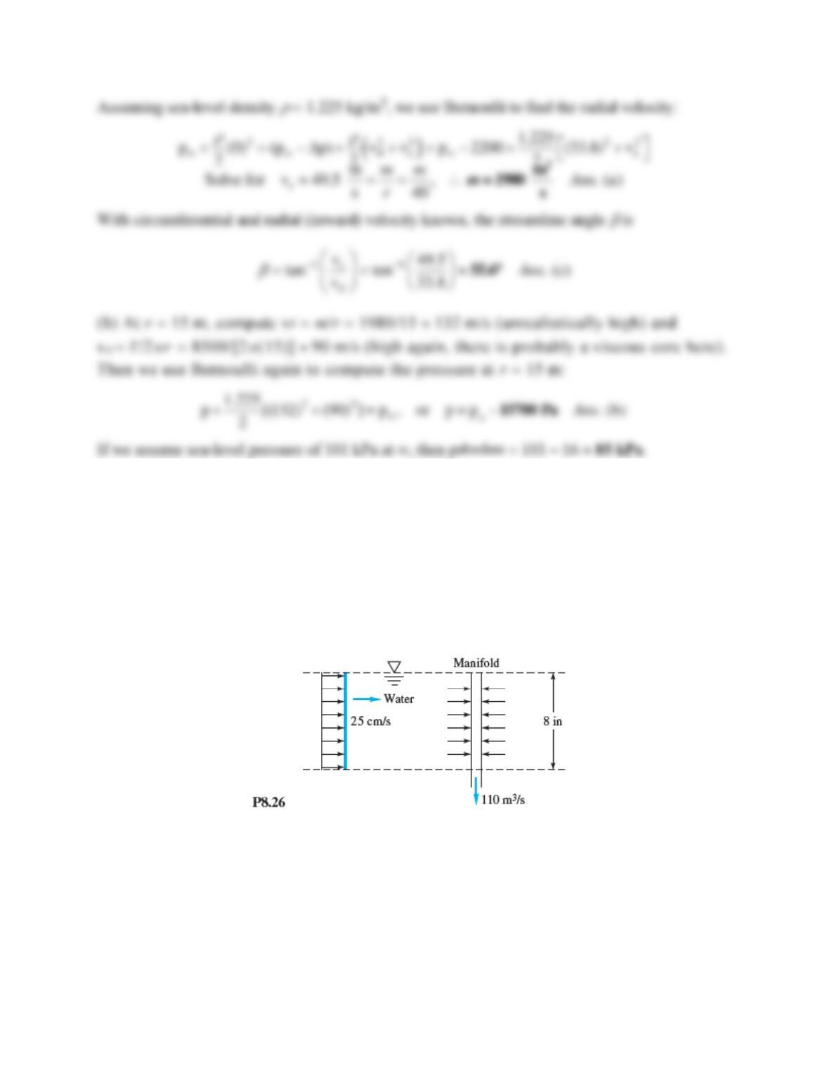
Problem 8.26
A coastal power plant takes in cooling water through a vertical perforated manifold, as in
Fig. P8.26. The total volume flow intake is 110 m3/s. Currents of 25 cm/s flow past the manifold,
as shown. Estimate (a) how far downstream and (b) how far normal to the paper the effects of the
intake are felt in the ambient 8-m-deep waters.
Solution 8.26
The sink strength m leads to the desired dimensions. The distance downstream from the sink is a
and the distance normal to the paper is pa (see Fig. 8.6):
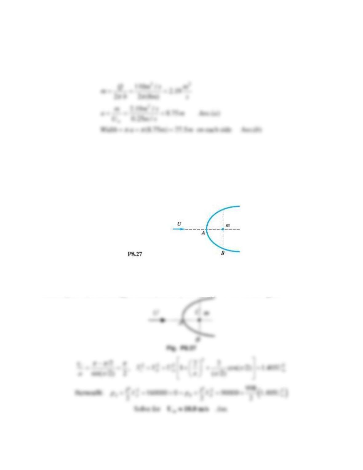
Problem 8.27
Water at 20°C flows past a half-body as shown in Fig. P8.27. Measured pressures at points A
and B are 160 kPa and 90 kPa, respectively, with uncertainties of 3 kPa each. Estimate the
stream velocity and its uncertainty.
Solution 8.27
Since Eq. (8.18) is for the upper surface, use it by noting that VC = VB in the figure:
Problem 8.28
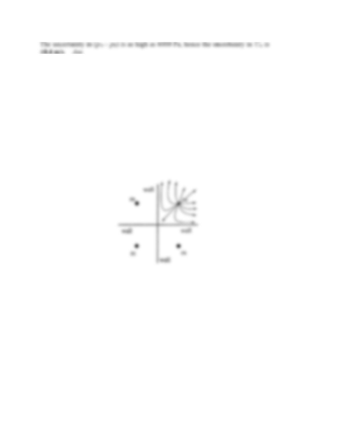
Sources of equal strength m are placed at the four symmetric positions:
(a, a), (–a, a), (–a, –a), and (a, –a).
Sketch the streamline and potential line patterns. Do any plane “walls” appear?
Solution 8.28
This is a double-image flow and creates two walls, as shown. Each quadrant has the same
pattern: a source in a “corner.” Ans.
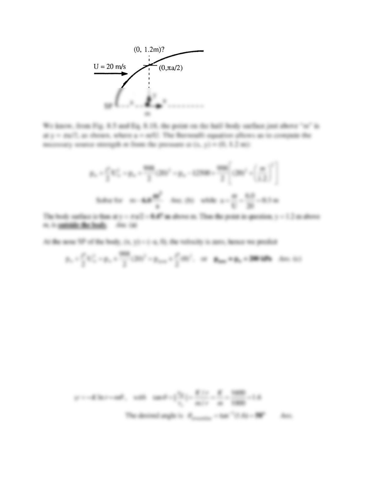
Problem 8.29
A uniform water stream, U = 20 m/s and
= 998 kg/m3, combines with a source at the origin to
form a half–body. At (x, y) = (0, 1.2 m), the pressure is 12.5 kPa less than p. (a) Is this point outside the
body? Estimate (b) the appropriate source strength m and (c) the pressure at the nose of the body.
Solution 8.29
Problem 8.30
A tornado is simulated by a line sink m = –1000 m2/s plus a line vortex K = 1600 m2/s. Find the angle
between any streamline and a radial line, and show that it is independent of both r and
. If this
tornado forms in sea-level standard air, at what radius will the local pressure be equivalent to
29 inHg?
Solution 8.30
For sea-level air take p = 101350 Pa and
= 1.2255 kg/m3. The combined stream function of this
flow is
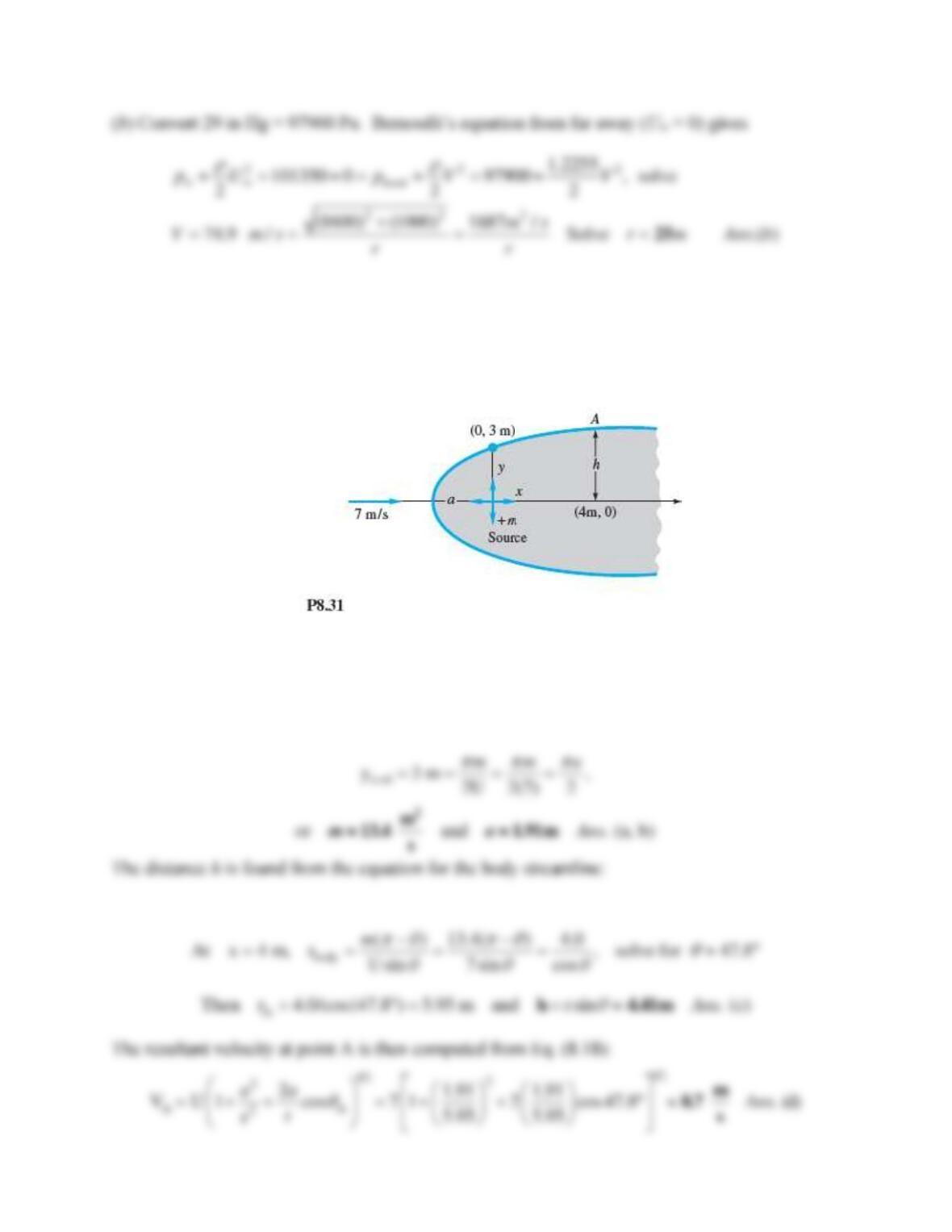
Problem 8.31
A Rankine half-body is formed as shown in Fig. P8.31. For the stream velocity and body dimension
shown, compute (a) the source strength m in m2/s, (b) the distance a, (c) the distance h, and (d) the total
velocity at point A.
Solution 8.31
The vertical distance above the origin is a known multiple of m and a:
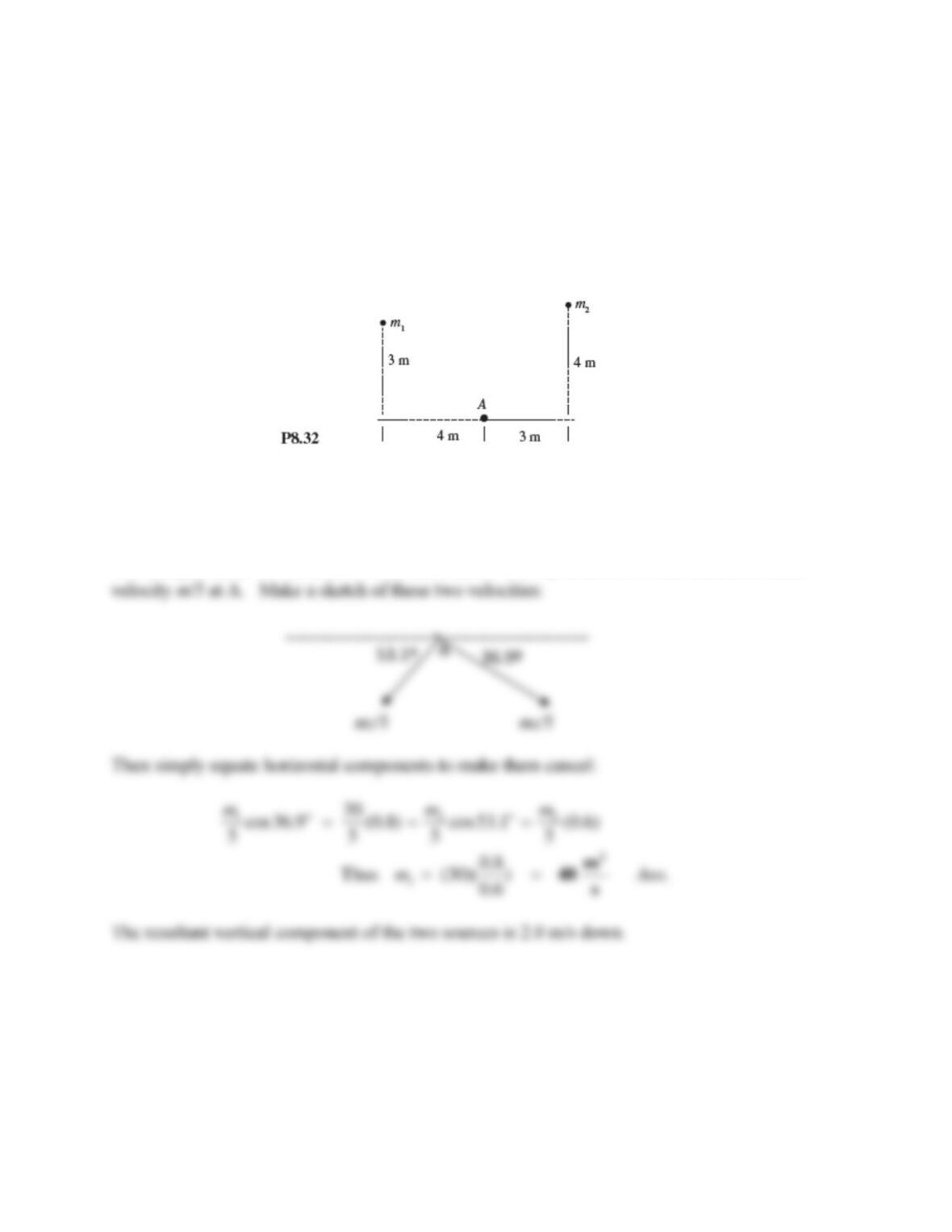
Problem 8.32
Line sources m1 and m2 are near point A, as in Fig. P8.32. If m1 = 30 m2/2, find the value of m2
for which the resultant velocity at point A is exactly vertical.
Solution 8.32
Note that the horizontal line going through A is not a “wall”. There are no image sources below
that line, just these two sources. Both sources are 5 m away from A, so each induces a radial
Problem 8.33
Sketch the streamlines, especially the body shape, due to equal line sources
+m at (0, +a) and (0, –a)
plus a uniform stream U
=
ma.
Solution 8.33
Problem 8.34
Consider three equally spaced sources of strength m placed at (x, y) = (+a, 0), (0, 0), and (−a, 0).
Sketch the resulting streamlines, noting the position of any stagnation points. What would the
pattern look like from afar?
Solution 8.34
Problem 8.35
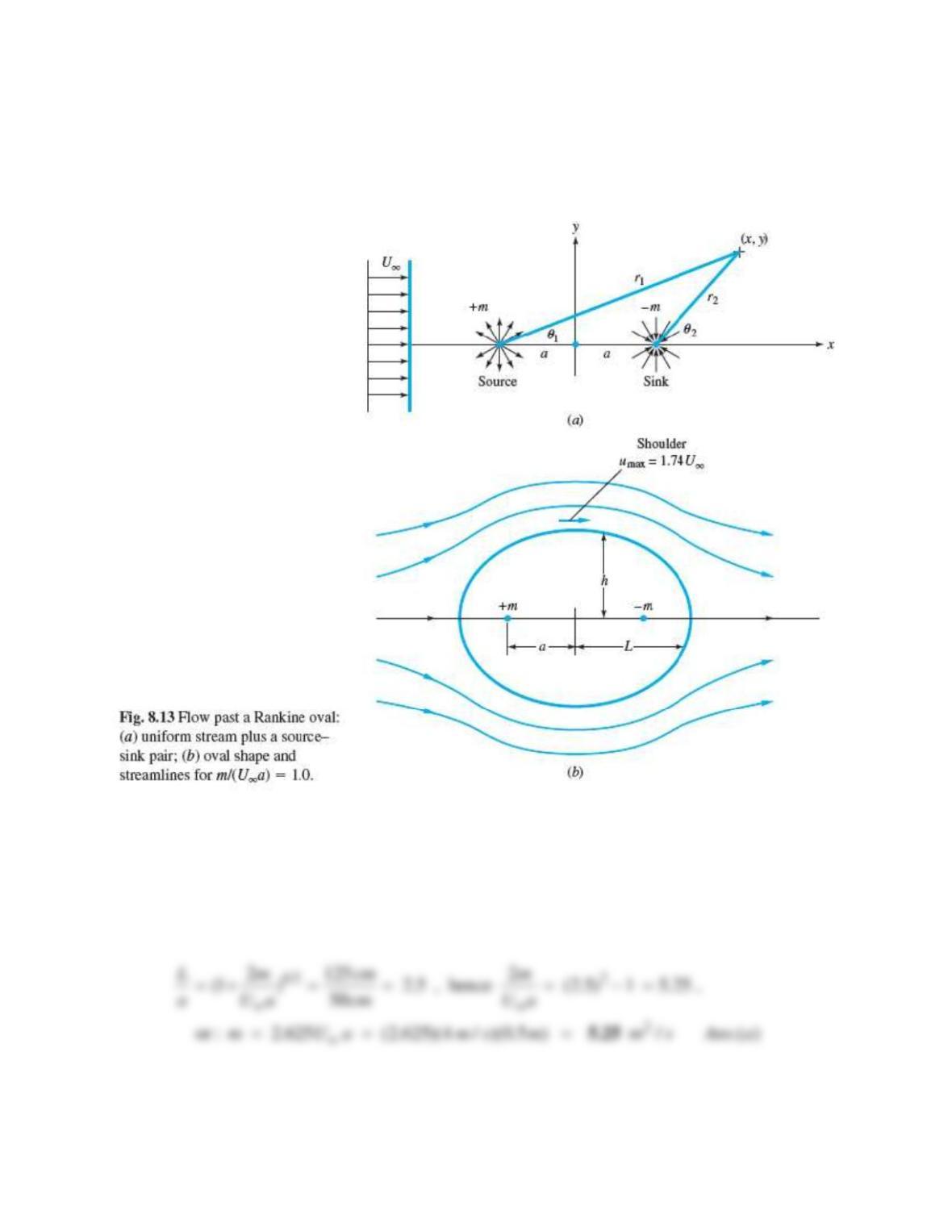
A uniform stream, U = 4 m/s, approaches a Rankine oval as in Fig. 8.13, with a = 50 cm.
(a) Find the strength m of the source-sink pair, in m2/s, which will cause the total length of the
oval to be 250 cm. (b) What is the maximum width of this oval?
Solution 8.35
(a) The straightforward, but unsatisfying, way to find length is to simply use Eq. (8.35) for the
half-length L of the oval. We are given a = 50 cm and L = 250/2 = 125 cm. Thus
Problem 8.36
When a line source-sink pair with m = 2 m2/s is combined with a uniform stream, it forms a
Rankine oval whose minimum dimension is 40 cm. If a = 15 cm, what are the stream velocity
and velocity at the shoulder? What is the maximum dimension?
Solution 8.36
We know h/a = 20/15, so from Eq. (8.30) we may determine the stream velocity:
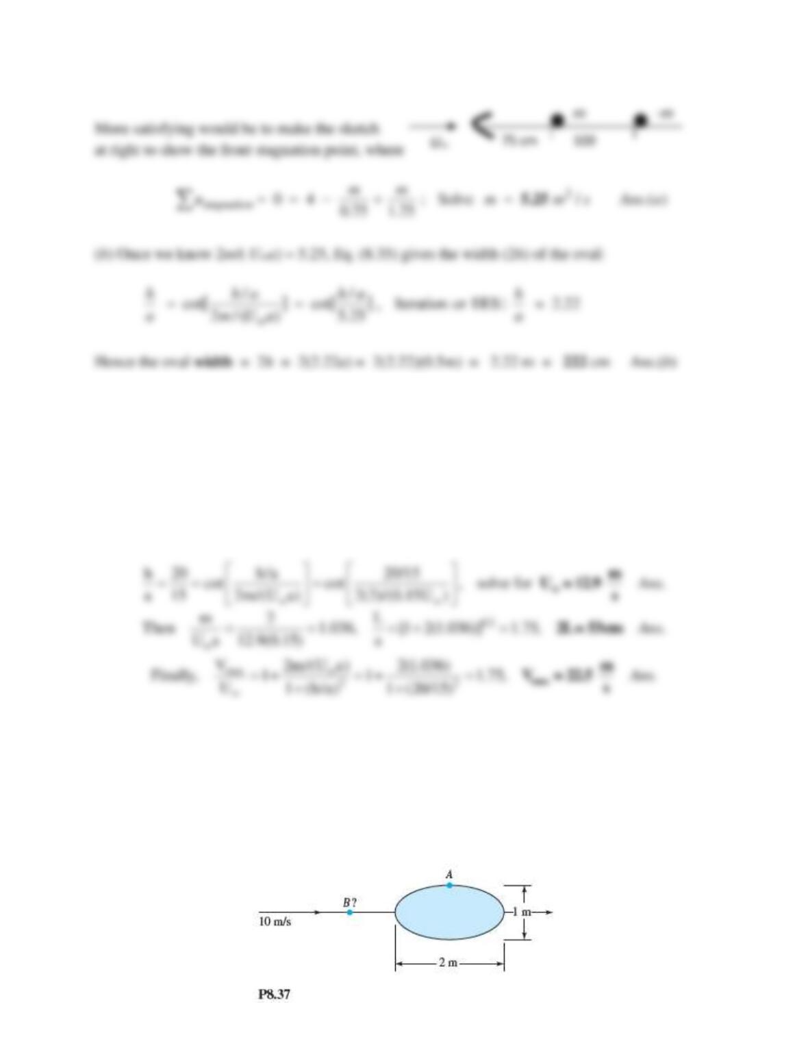
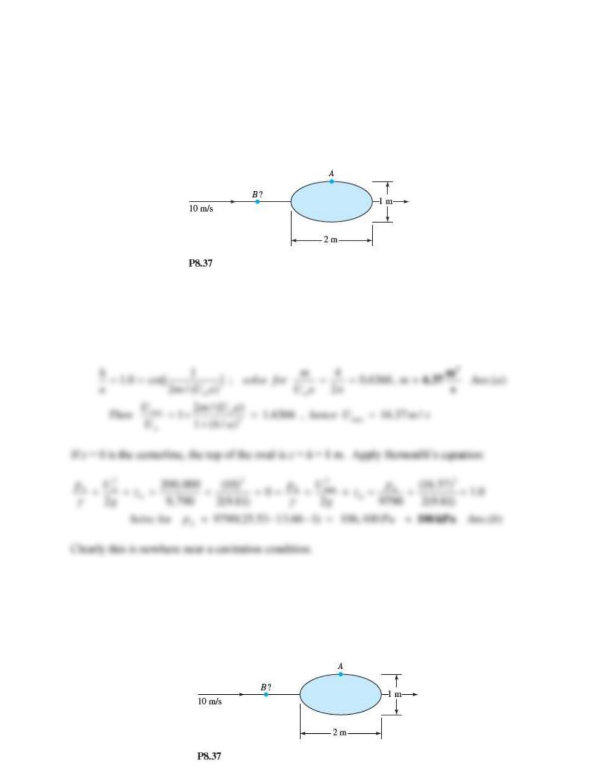
Problem 8.37
A Rankine oval 2 m long and 1 m high is immersed in a stream U = 10 m/s, as in Fig. P8.37.
Estimate (a) the velocity at point A and (b) the location of point B where a particle approaching
the stagnation point achieves its maximum deceleration.
Solution 8.37
(a) With L/h = 2.0, we may evaluate Eq. (8.30) to find the source-sink strength:
1/2
h h/a L 2m
cot and 1
a 2m/(U a) a U a
= = +
max
Problem 8.38
Consider potential flow of a uniform stream in the x direction plus two equal sources, one at
(x, y) = (0, +a) and the other at (x, y) = (0, -a). Sketch your ideas of the body contours that would
arise if the sources were (a) very weak; and (b) very strong.
Solution 8.38
Weak sources (m << U a) create two approximate half-bodies, strong sources
Problem 8.39
A large Rankine oval, with a = 1 m and h = 1 m, is immersed in 20ºC water flowing at 10 m/s.
The upstream pressure on the oval centerline is 200 kPa. Calculate (a) the value of m; and
(b) the pressure on the top of the oval (analogous to point A in Fig. P8.37).
Solution 8.39
For water at 20ºC, take ρ = 998 kg/m3. We are given h/a = 1m/1m = 1.0, which unfortunately is
not in Table 8.1. But we can see that m/(U∞a) is less than 1.0, and we can iterate Eqs. (8.35) to
find its value. These equations are easily solved when h/a is known:
Problem 8.40
Modify the Rankine oval in Fig. P8.37 so that the stream velocity and body length are the same
but the thickness is unknown (not 1 m). The fluid is water at 30C and the pressure far upstream
along the body centerline is 108 kPa. Find the body thickness for which cavitation will occur at
point A.
Solution 8.40
For water at 30C, take
= 996 kg/m3 and pvap = 4242 Pa. Bernoulli’s equation between far
upstream and point A yields
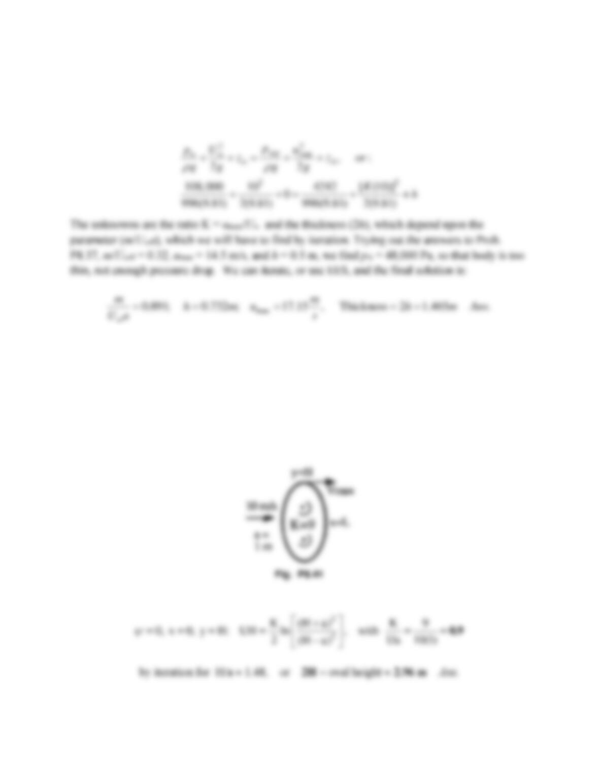
Problem 8.41
A Kelvin oval is formed by a line-vortex pair with K = 9 m2s, a = 1 m, and U = 10 ms. What
are the height, width, and shoulder velocity of this oval?
Solution 8.41
With reference to Fig. 8.12 and Eq. (8.41), the oval is described by
Problem 8.42
The vertical keel of a sailboat approximates a Rankine oval 125 cm long and 30 cm thick. The
boat sails in seawater in standard atmosphere at 14 knots, parallel to the keel. At a section 2 m
below the surface, estimate the lowest pressure on the surface of the keel.
Solution 8.42
Assume standard sea level pressure of 101,350 Pa. From Table A.3, the density of seawater is
approximately 1025 kg/m3. At 2 meters depth, we would have
Problem 8.43
Water at 20ºC flows past a 1-m-diameter circular cylinder. The upstream centerline pressure is
128,500 Pa. If the lowest pressure on the cylinder surface is exactly the vapor pressure, estimate,
by potential theory, the stream velocity.
Solution 8.43
For water at 20ºC, ρ = 998 kg/m3 and, from Table A.5, pvap = 2337 Pa. The lowest pressure point
is the top of the cylinder. Write Bernoulli’s equation from that point to the freestream,