Problem 8.44
Suppose that circulation is added to the cylinder flow of Prob. 8.43 sufficient to place the
stagnation points at
= 35° and 145°. What is the required vortex strength K in m2/s? Compute
the resulting pressure and surface velocity at (a) the stagnation points, and (b) the upper and
lower shoulders. What will be the lift per meter of cylinder width?
Problem 8.43
Water at 20ºC flows past a 1-m-diameter circular cylinder. The upstream centerline pressure is
128,500 Pa. If the lowest pressure on the cylinder surface is exactly the vapor pressure, estimate,
by potential theory, the stream velocity.
Solution 8.44
Recall that Prob. 8.43 was for water at 20°C flowing at 6 m/s past a 1-m–diameter cylinder, with
p = 200 kPa. From Eq. (8.35),
2
Problem 8.45
If circulation K is added to the cylinder flow in Prob. 8.43, (a) for what value of K will the flow
begin to cavitate at the surface? (b) Where on the surface will cavitation begin? (c) For this
condition, where will the stagnation points lie?
Problem 8.43
Water at 20ºC flows past a 1-m-diameter circular cylinder. The upstream centerline pressure is
128,500 Pa. If the lowest pressure on the cylinder surface is exactly the vapor pressure, estimate,
by potential theory, the stream velocity.
Solution 8.45
Recall that Prob. 8.43 was for water at 20°C flowing at 6 m/s past a 1-m-diameter cylinder, with
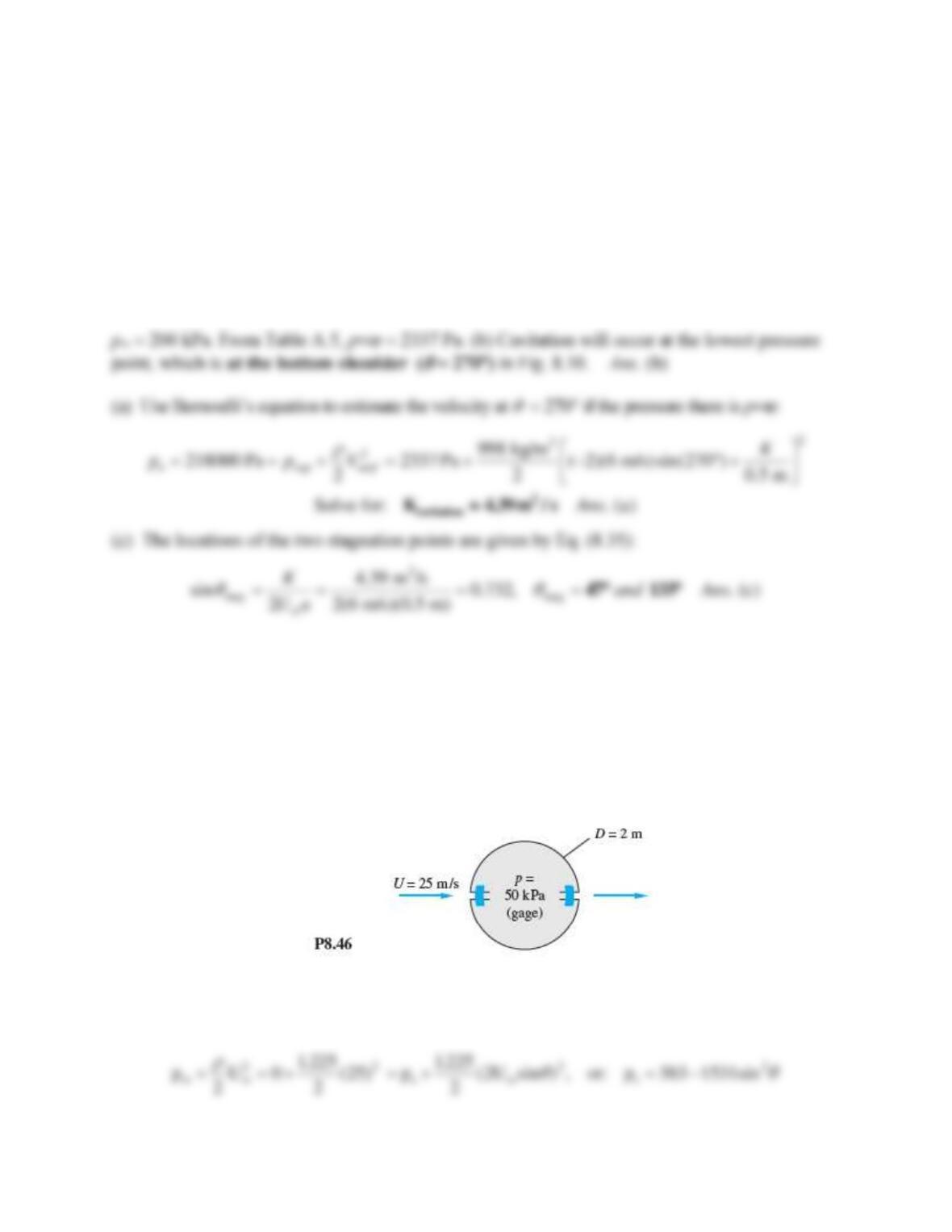
Problem 8.46
A cylinder is formed by bolting two semicylindrical channels together on the inside, as shown in
Fig. P8.46. There are 10 bolts per meter of width on each side, and the inside pressure is 50 kPa
(gage). Using potential theory for the outside pressure, compute the tension force in each bolt if
the fluid outside is sea-level air.
Solution 8.46
For sea-level air take
= 1.225 kgm3. Use Bernoulli to find surface pressure:
Problem 8.47
A circular cylinder is fitted with two surface-mounted pressure sensors, to measure pressure at pa
at θ = 180 and pb at θ =105. The intention is to use the cylinder as a stream velocimeter.
Using inviscid theory, derive a formula for calculating U from pa, pb,
, and the cylinder
radius a.
Solution 8.47
We relate the pressures to surface velocities from Bernoulli’s equation:
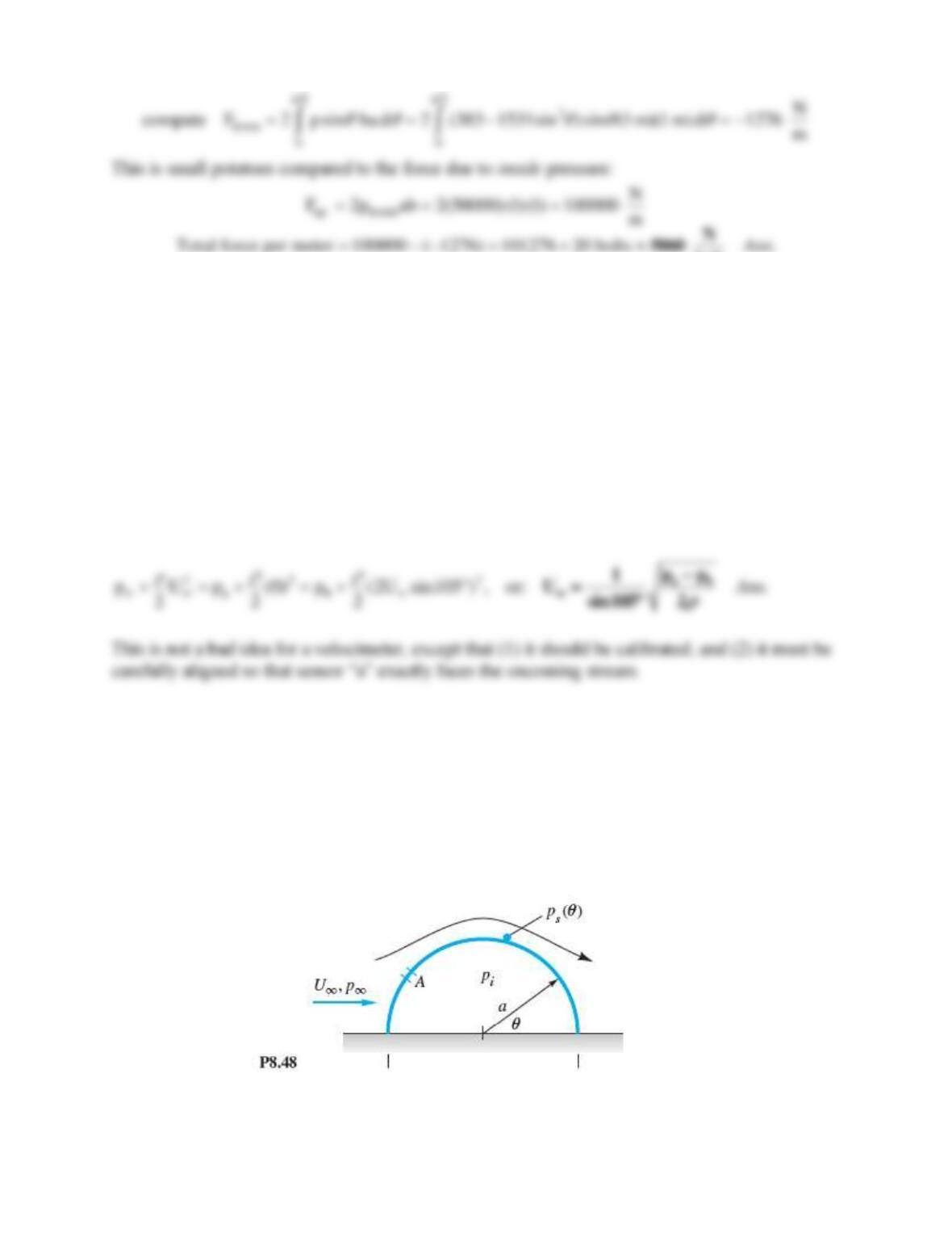
Problem 8.48*
Wind at U and p flows past a Quonset hut which is a half-cylinder of radius a and length L
(Fig. P8.48). The internal pressure is pi. Using inviscid theory, derive an expression for the
upward force on the hut due to the difference between pi and ps.
Solution 8.48
The analysis is similar to Prob. 8.46 on the previous page. If po is the stagnation pressure at the
nose (
= 180), the surface pressure distribution is
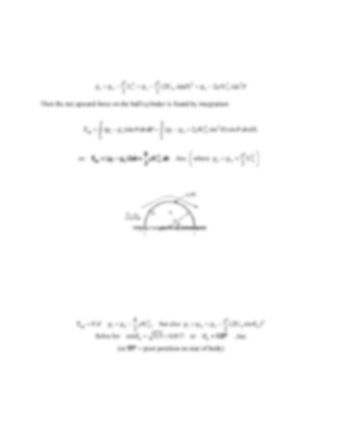
Problem 8.49
In strong winds the force in Prob. 8.48 above can be quite large. Suppose that a hole is
introduced in the hut roof at point A to make pi equal to the surface pressure there. At what
angle
should hole A be placed to make the net wind force zero?
Solution 8.49
Set F = 0 in Prob. 8.48 and find the proper pressure from Bernoulli:
Problem 8.50
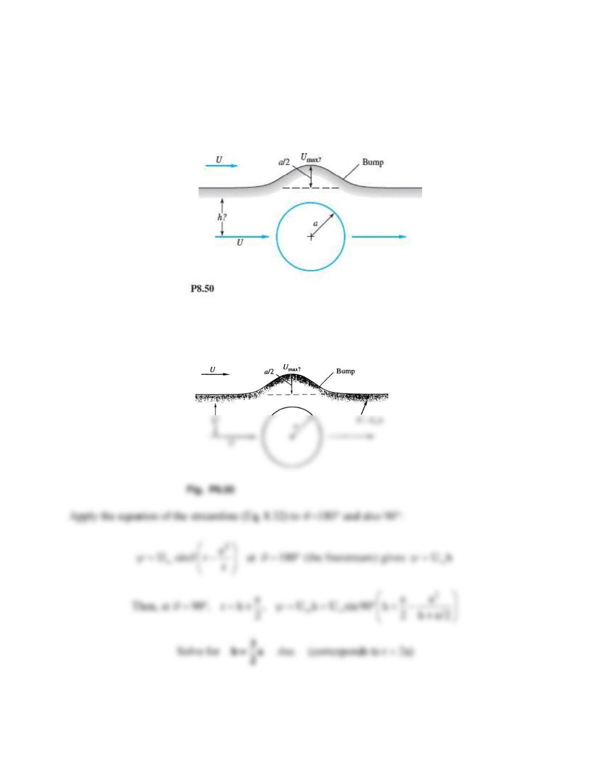
It is desired to simulate flow past a two-dimensional ridge or bump by using a streamline that
passes above the flow over a cylinder, as in Fig. P8.50. The bump is to be a/2 high, where a is
the cylinder radius. What is the elevation h of this streamline? What is Umax on the bump
compared with stream velocity U?
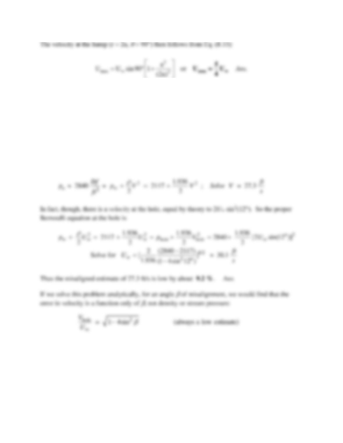
Solution 8.50
Problem 8.51
A hole is placed in the front of a cylinder to measure the stream velocity of sea-level fresh water.
The measured pressure at the hole is 2840 lbf/ft2. If the hole is misaligned by 12 from the
stream, and misinterpreted as stagnation pressure, what is the error in velocity?
Solution 8.51
Take sea level pressure as 2117 lbf/ft2 and
water = 1.936 slug/ft3. If we think the velocity at the
holes is zero (stagnation), then Bernoulli’s equation predicts
Problem 8.52
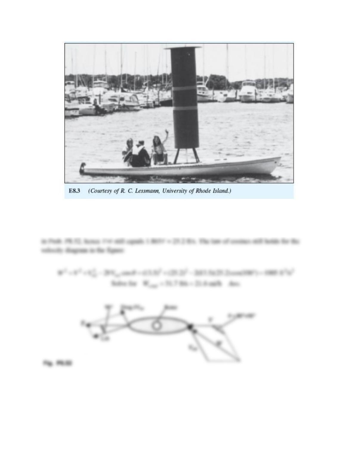
The Flettner rotor sailboat in Fig. E8.3 has a water drag coefficient of 0.006 based on a wetted
area of 45 ft2. If the rotor spins at 220 revmin, find the maximum boat velocity that can be
achieved in a 15 mih wind. What is the optimum angle between the boat and the wind?
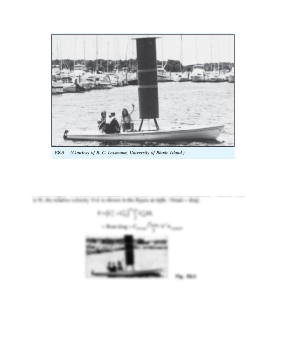
Solution 8.52
Recall that the rotor has a diameter of 2.5 ft and is 10 ft high. Standard air density is
0.00238 slugft3. As in Ex. 8.2, estimate CL 2.5 and CD 0.7. If the boat speed is V and the wind
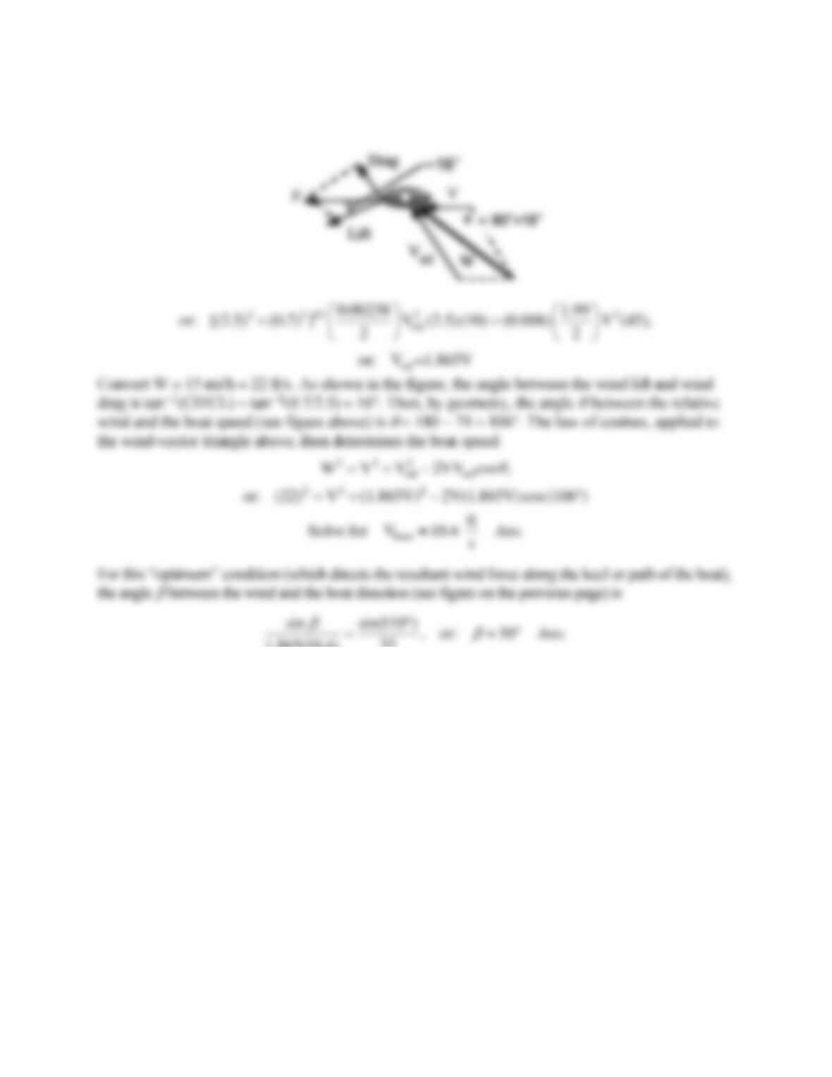
1.865(10.4) 22 Ans
Problem 8.53
Modify Prob. P8.52 as follows. For the same sailboat data, find the wind velocity, in mi/h, which
will drive the boat at an optimum speed of 8 kn parallel to its keel.
Problem 8.52
The Flettner rotor sailboat in Fig. E8.3 has a water drag coefficient of 0.006 based on a wetted
area of 45 ft2. If the rotor spins at 220 revmin, find the maximum boat velocity that can be
achieved in a 15 mih wind. What is the optimum angle between the boat and the wind?
Solution 8.53
Convert 8 knots = 13.5 ft/s. Again estimate CL 2.5 and CD 0.7. The geometry is the same as
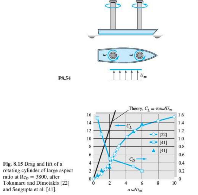
Problem 8.54
The original Flettner rotor ship was approximately 100 ft long, displaced 800 tons, and had a
wetted area of 3500 ft2. As sketched in Fig. P8.54, it had two rotors 50 ft high and 9 ft in
diameter rotating at 750 rmin, which is far outside the range of Fig. 8.15. The measured lift
and drag coefficients for each rotor were about 10 and 4, respectively. If the ship is moored
and subjected to a crosswind of 25 fts, as in Fig. P8.54, what will the wind force parallel and
normal to the ship centerline be? Estimate the power required to drive the rotors.
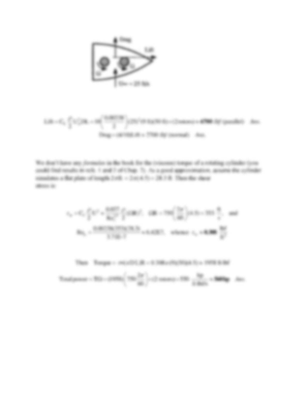
Solution 8.54
For sea-level air take
= 0.00238 slugft3 and
= 3.71E−7 slugft s. Then compute the forces:
Problem 8.55
Assume that the Flettner rotor ship of Fig. P8.54 has a water resistance coefficient of 0.005. How
fast will the ship sail in seawater at 20C in a 20 ft/s wind if the keel aligns itself with the resultant
force on the rotors? [This problem involves relative velocities.]
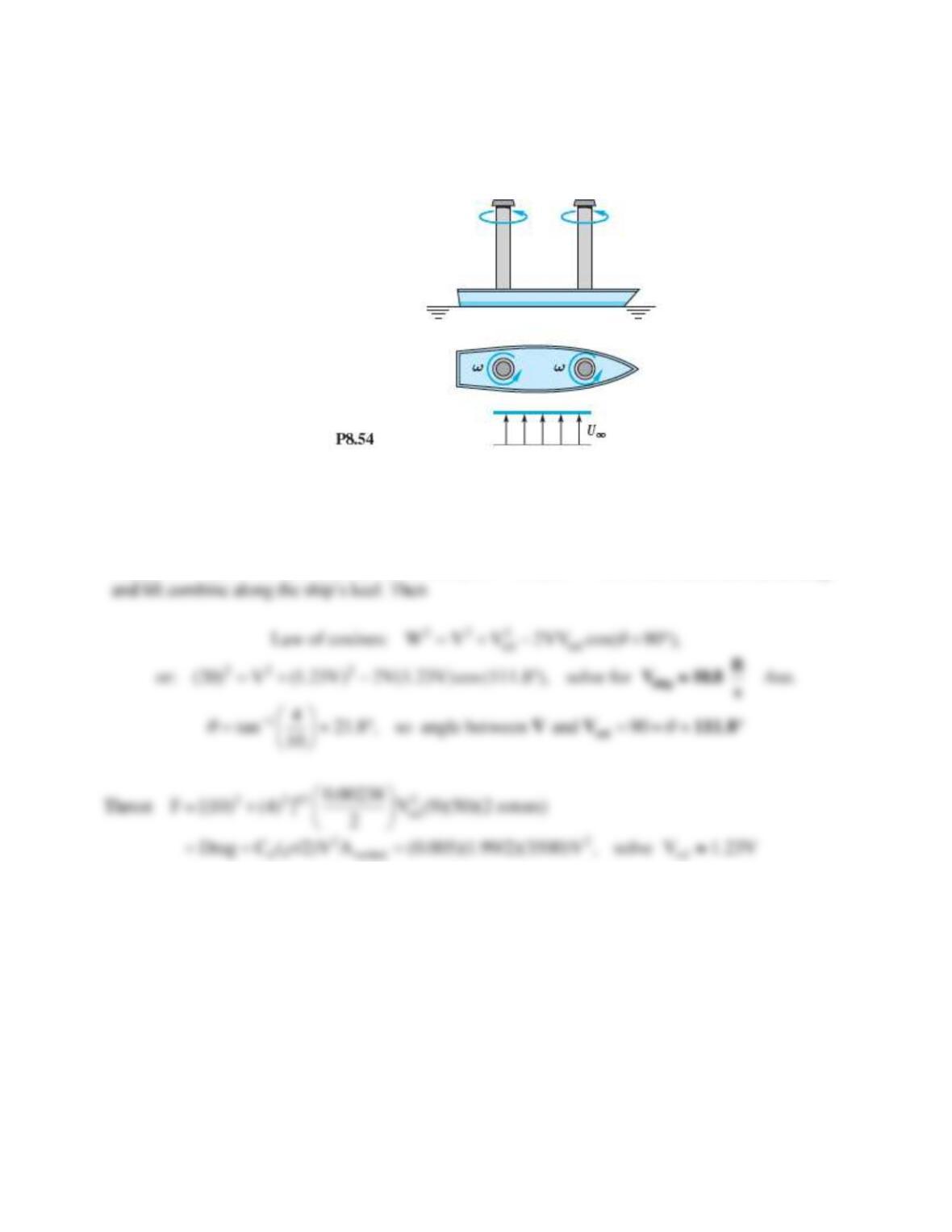
Solution 8.55
For air, take
= 0.00238 slug/ft3. For seawater, take
= 1.99 slug/ft3 and
= 2.09E–5 slug/fts.
Recall D = 9 ft, L = 50 ft, 2 rotors at 750 rev/min, CL 10.0, CD 4.0. In the sketch above, the drag
Problem 8.56
A proposed free-stream velocimeter would use a cylinder with pressure taps at
= 180° and at
150°. The pressure difference would be a measure of stream velocity U . However, the cylinder
must be aligned so that one tap exactly faces the free-stream. Let the misalignment angle be
,
that is, the two taps are at (180° +
) and (150° +
) . Make a plot of the percentage error in
velocity measurement in the range –20°
+20° and comment on the idea.
Solution 8.56
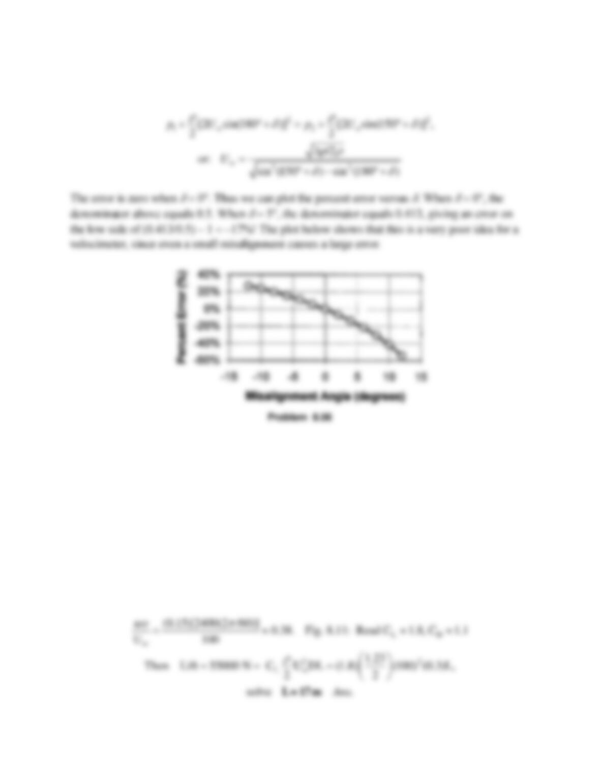
Recall from Eq. (8.34) that the surface velocity on the cylinder equals 2Usin
. Apply Bernoulli’s
equation at both points, 180° and 150°, to solve for stream velocity:
Problem 8.57
In principle, it is possible to use rotating cylinders as aircraft wings. Consider a cylinder 30 cm in
diameter, rotating at 2400 rev/min. It is to lift a 55-kN airplane flying at 100 m/s. What should
the cylinder length be? How much power is required to maintain this speed? Neglect end effects
on the rotating wing.
Solution 8.57
Assume sea-level air,
= 1.23 kg/m3. Use Fig. 8.11 for lift and drag:
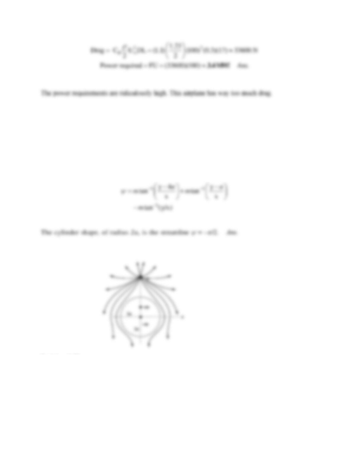
Problem 8.58
Plot the streamlines due to the combined flow of a line sink –m at the origin, plus line sources +m at
(a, 0) and (4a, 0). [Hint: A cylinder of radius 2a appears.]
Solution 8.58
The overall stream function is
Problem 8.59
The Transition® car-plane in Fig. 7.30 has a gross weight of 1,430 lbf. Suppose we replace the
wing with a 1-ft-diameter rotating cylinder 20 ft long. (a) What rotation rate from Fig. 8.15, in
r/min, would lift the plane at a take-off speed of 55 mi/h? (b) Estimate the cylinder drag at this
rotation rate. Neglect fuselage lift and cylinder end effects.
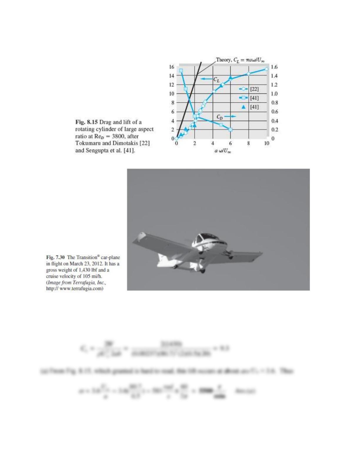
Solution 8.59
Assume sea-level air, ρ = 0.00237 slug/ft3. Convert 65 mi/h = 80.7 ft/s. The lift coefficient, with
a = 0.5 ft and b = 20 ft, is
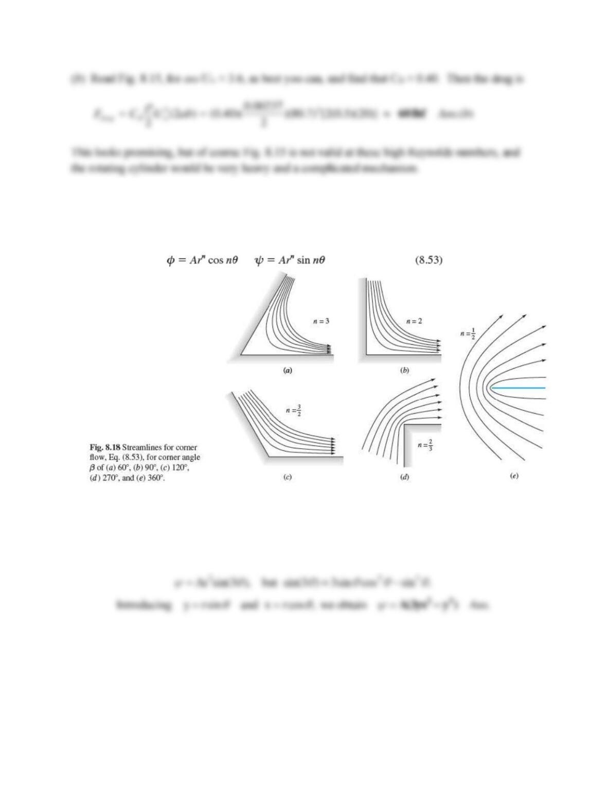
Problem 8.60
One of the corner–flow patterns of Fig. 8.18 is given by the cartesian stream function
= A(3yx2 – y3). Which one? Can this correspondence be proven from Eq. (8.53)?
Solution 8.60
This
is Fig. 8.18a, flow in a 60 corner. [Its velocity potential was given earlier Eq. (8.49) of
the text.] The trigonometric form (Eq. 8.49 for n = 3) is
Problem 8.61
Plot the streamlines of Eq. (8.53) in the upper right quadrant for n = 4. How does the velocity
increase with x outward along the x axis from the origin? For what corner angle and value of n
would this increase be linear in x? For what corner angle and n would the increase be as x5?
Solution 8.61
For n = 4, we have flow in a 45 corner, as shown. Compute
Problem 8.62
Combine stagnation flow, Fig. 8.19b, with a source at the origin:
2
f(z) Az ln(z)m=+
Plot the streamlines for m = AL2, where L is a length scale. Interpret.
Solution 8.62
The imaginary part of this complex potential is the stream function:
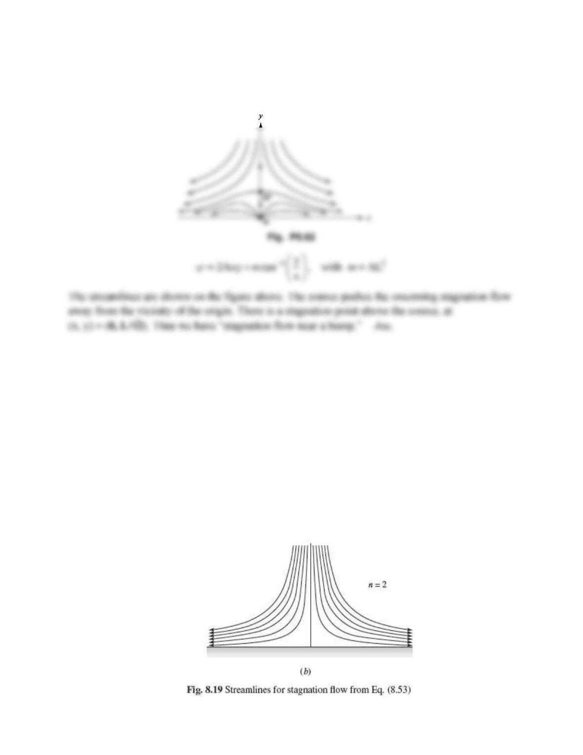
Problem 8.63
The superposition in Prob. 8.62 above leads to stagnation flow near a curved bump, in contrast to
the flat wall of Fig. 8.19b. Determine the maximum height H of the bump as a function of the
constants A and m.
Problem 8.62
Combine stagnation flow, Fig. 8.19b, with a source at the origin:
2
f(z) Az ln(z)m=+
Plot the streamlines for m = AL2, where L is a length scale. Interpret.
Solution 8.63
The bump crest is a stagnation point:
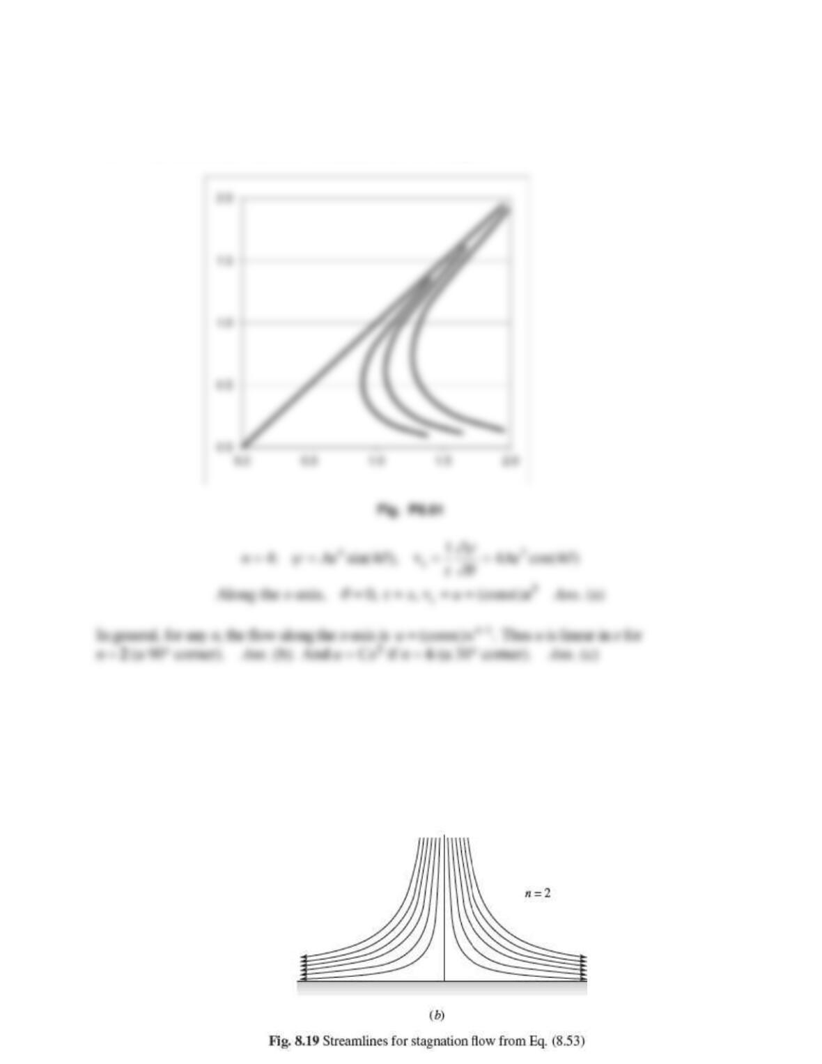
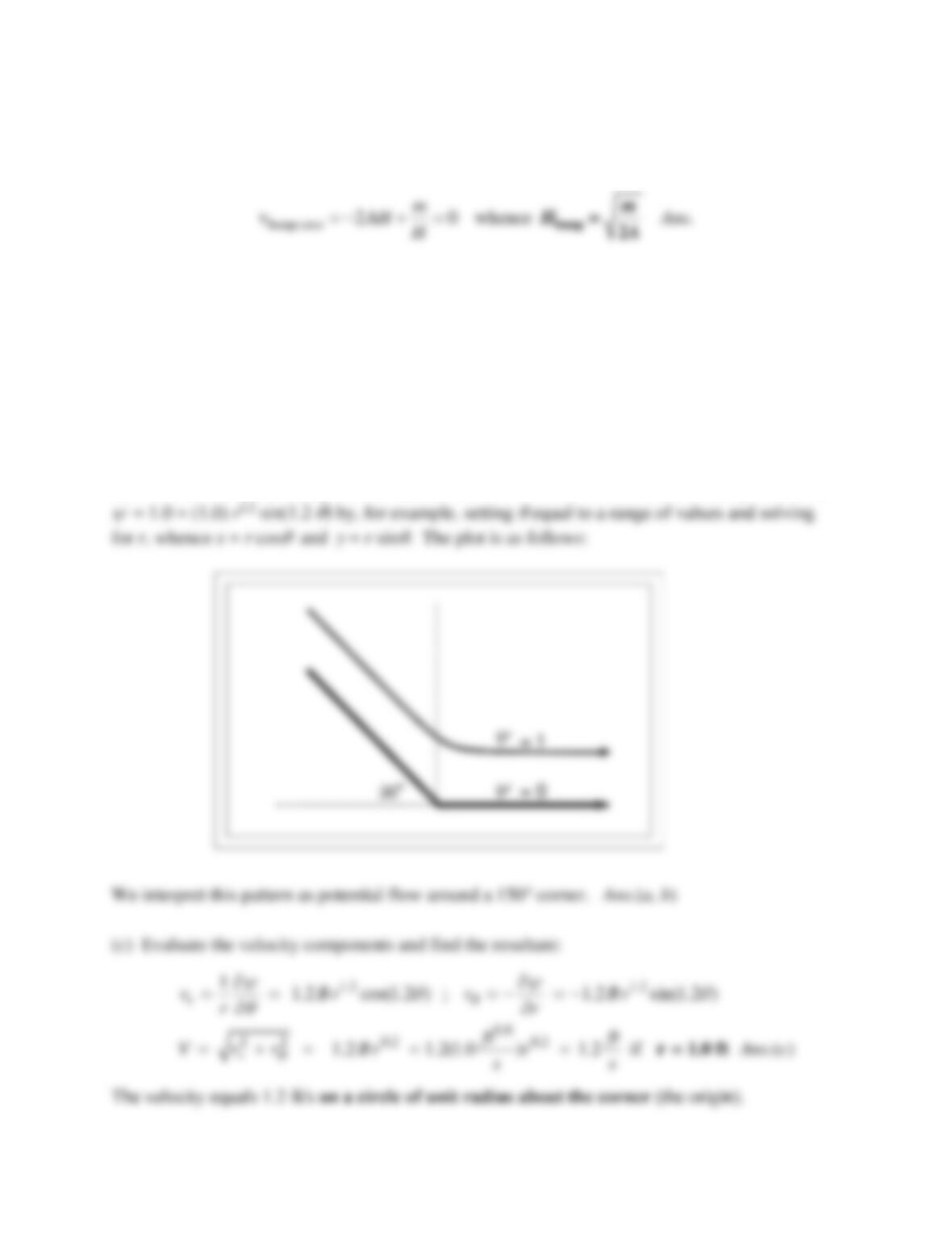
Problem 8.64
Consider the polar-coordinate stream function
= B r1.2 sin(1.2
), with B equal, for
convenience, to 1.0 ft0.8/s. (a) Plot the streamline
= 0 in the upper half plane. (b) Plot the
streamline
= 1.0 and interpret the flow pattern. (c) Find the locus of points above
= 0 for
which the resultant velocity = 1.2 ft/s.
Solution 8.64
(a) We find that
= 0 along the two radial lines
= 0 and
= 150. (b) We can plot the line
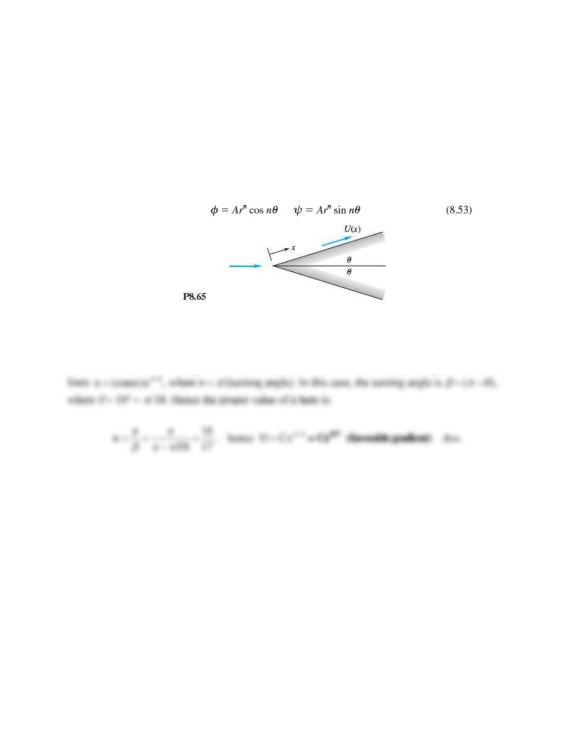
Problem 8.65
Potential flow past a wedge of half-angle
leads to an important application of laminar-
boundary-layer theory called the Falkner-Skan flows [15, pp. 239-245]. Let x denote distance
along the wedge wall, as in Fig. P8.65, and let
= 10. Use Eq. (8.53) to find the variation of
surface velocity U(x) along the wall. Is the pressure gradient adverse or favorable?
Solution 8.65
As discussed above, all wedge flows are “corner flows” and have a velocity along the wall of the