Problem 6.C1
A Pitot-static probe will be used to measure the velocity distribution in a water tunnel at 20C.
The two pressure lines from the probe will be connected to a U-tube manometer which uses a
liquid of specific gravity 1.7. The maximum velocity expected in the water tunnel is 2.3 m/s.
Your job is to select an appropriate U-tube from a manufacturer which supplies manometers of
heights 8, 12, 16, 24 and 36 in. The cost increases significantly with manometer height. Which of
these should you purchase?
Solution 6.C1
The pitot-static tube formula relates velocity to the difference between stagnation pressure po
and static pressure ps in the water flow:
Problem 6.C2
A pump delivers a steady flow of water (
,
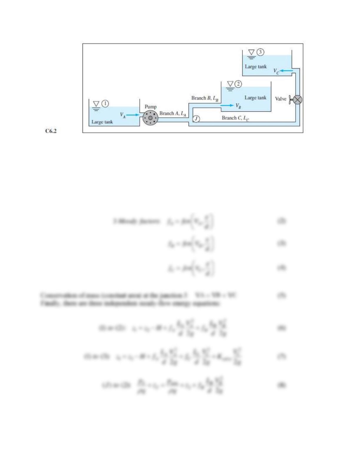
) from a large tank to two other higher-elevation
tanks, as in Fig. C6.2. The same pipe of diameter d and roughness
is used throughout. All
minor losses except through the valve are neglected, and the partially-closed valve has a loss
coefficient Kvalve. Turbulent flow may be assumed with all kinetic energy flux correction
coefficients equal to 1.06. The pump net head H is a known function of QA and hence also of
VA = QA/Apipe, for example,
2
A
H a bV ,=−
where a and b are constants. Subscript J refers to the
junction point at the tee where branch A splits into B and C. Pipe length LC is much longer than
LB. It is desired to predict the pressure at J, the three pipe velocities and friction factors, and the
pump head. Thus there are 8 variables: H, VA, VB, VC, fA, fB, fC, pJ. Write down the eight
equations needed to resolve this problem, but do not solve, since an elaborate iteration procedure
would be required.
Solution 6.C2
First, equation (1) is clearly the pump performance:
2
A
H a bV=−
(1)
Problem 6.C3
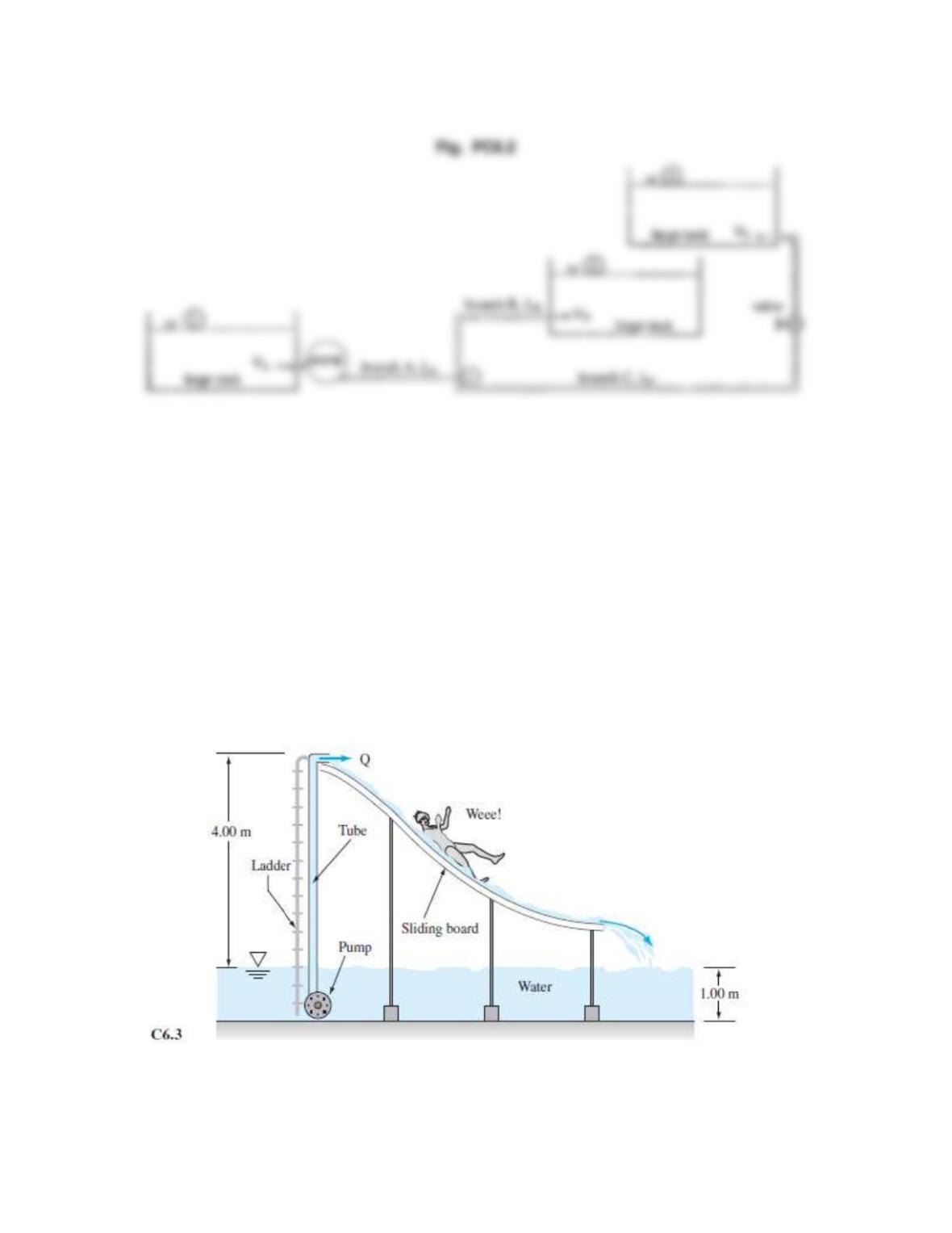
A small water slide is to be installed inside a swimming pool. See Fig. C6.3. The slide
manufacturer recommends a continuous water flow rate Q of 1.39 × 10⁻³ m3/s (about 22 gal/min)
down the slide, to ensure that the customers do not burn their bottoms. A pump is to be installed
under the slide, with a 5.00-m-long, 4.00-cm-diameter hose supplying swimming pool water for
the slide. The pump is 80 percent efficient and will rest fully submerged 1.00 m below the water
surface. The roughness inside the hose is about 0.0080 cm. The hose discharges the water at the
top of the slide as a free jet open to the atmosphere. The hose outlet is 4.00 m above the water
surface. For fully developed turbulent pipe flow, the kinetic energy flux correction factor is about
1.06. Ignore any minor losses here. Assume that ρ = 998 kg/m3 and υ = 1.00 × 10⁻⁶ m2/s for this
water. Find the brake horsepower (that is, the actual shaft power in watts) required to drive the
pump.
Solution 6.C3
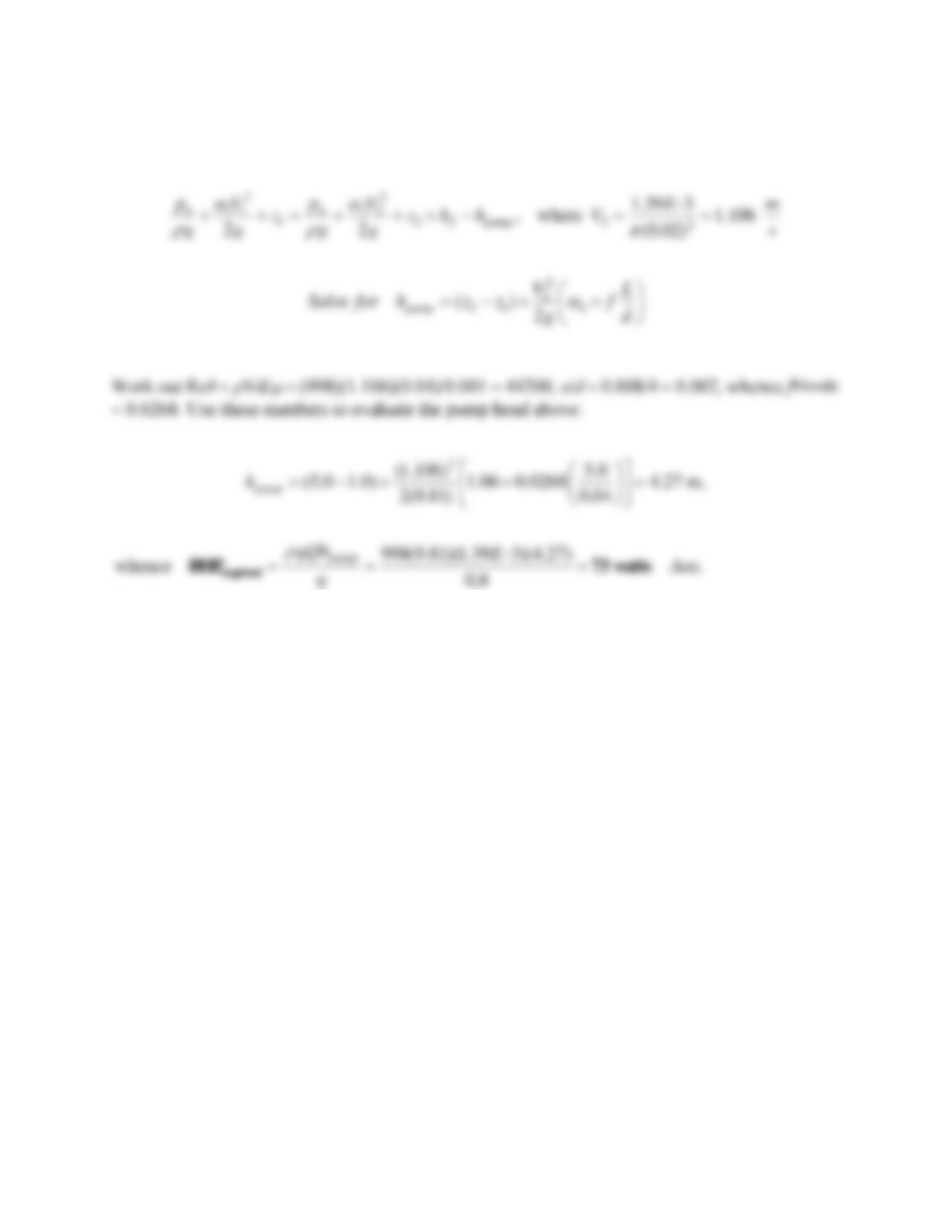
For water take
= 998 kg/m3 and
= 0.001 kg/ms. Write the steady-flow energy equation from
the water surface (1) to the outlet (2) at the top of the slide:
Problem 6.C4*
Suppose you build a rural house where you need to run a pipe to the nearest water supply, which
is fortunately at an elevation of about 1000 m above that of your house. The pipe will be 6.0 km
long (the distance to the water supply), and the gage pressure at the water supply is 1000 kPa.
You require a minimum of 3.0 gal/min of water when the end of your pipe is open to the
atmosphere. To minimize cost, you want to buy the smallest-diameter pipe possible. The pipe
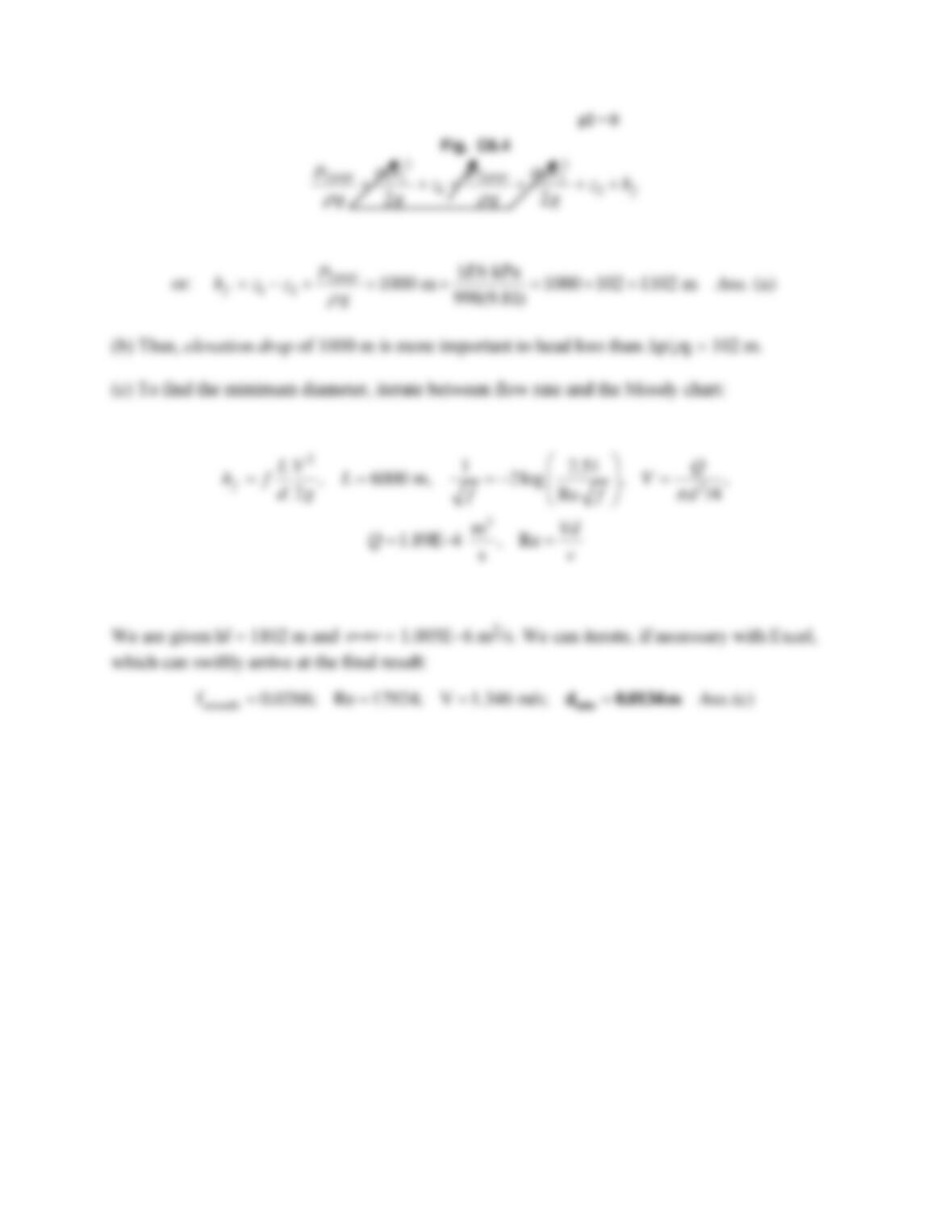
you will use is extremely smooth. (a) Find the total head loss from the pipe inlet to its exit.
Neglect any minor losses due to valves, elbows, entrance lengths, and so on, since the length is
so long here and major losses dominate. Assume the outlet of the pipe is open to the atmosphere.
(b) Which is more important in this problem, the head loss due to elevation difference or the
head loss due to pressure drop in the pipe? (c) Find the minimum required pipe diameter.
Solution 6.C4
Convert 3.0 gal/min to 1.89E−4 m3/s. Let 1 be the inlet and 2 be the outlet and write the steady-
flow energy equation:
Problem 6.C5
Water at room temperature flows at the same volume flow rate, Q = 9.4 × 10⁻⁴ m3/s, through two
ducts, one a round pipe and one an annulus. The cross-sectional area A of the two ducts is
identical, and all walls are made of commercial steel. Both ducts are the same length. In the cross
sections shown in Fig. C6.5 R = 15.0 mm and a = 25.0 mm. (a) What is the radius b such that the
cross-sectional areas of the two ducts are identical? (b) Compare the frictional head loss hf per
unit length of pipe for the two cases, assuming fully developed flow. For the annulus, do both a
quick estimate (using the hydraulic diameter) and a more accurate estimate (using the effective
diameter correction), and compare. (c) If the losses are different for the two cases, explain why.
Which duct, if any, is more “efficient”?
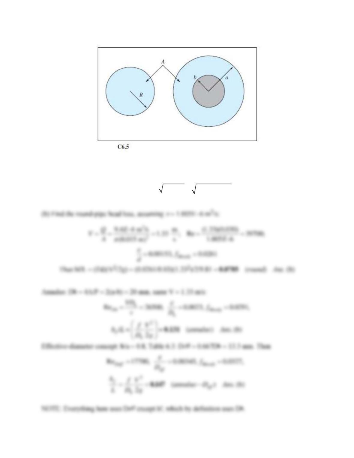
Solution 6.C5
(a) Set the areas equal:
2 2 2 2 2 2 2
( ), : (25) (15) 20 mm (a)A R a b or b a R Ans.
= = − = − = − =
Problem 6.C6
John Laufer (NACA Tech. Rep. 1174, 1954) gave velocity data for 20C airflow in a smooth
24.7-cm-diameter pipe at Re 5 E5:
u/uCL:
1.0
0.997
0.988
0.959
0.908
0.847
0.818
0.771
0.690
r/R:
0.0
0.102
0.206
0.412
0.617
0.784
0.846
0.907
0.963
Source: John Laufer (NASA Tech Rep. 1174, 1954)
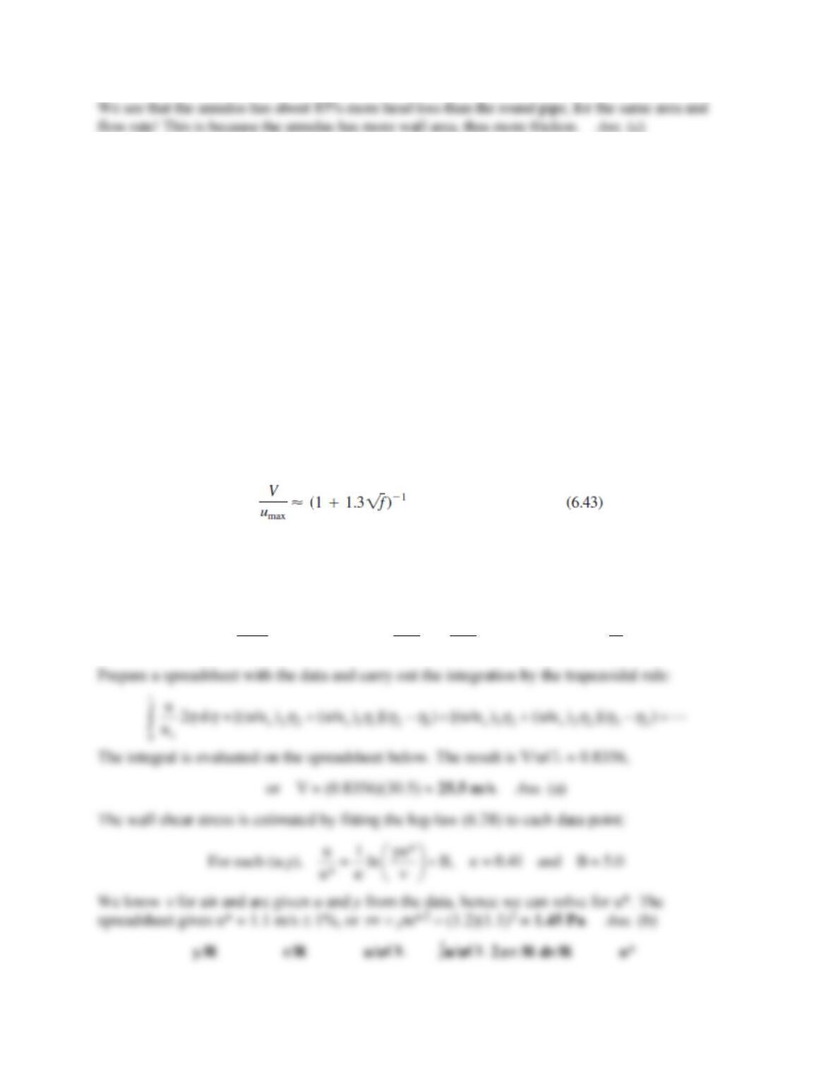
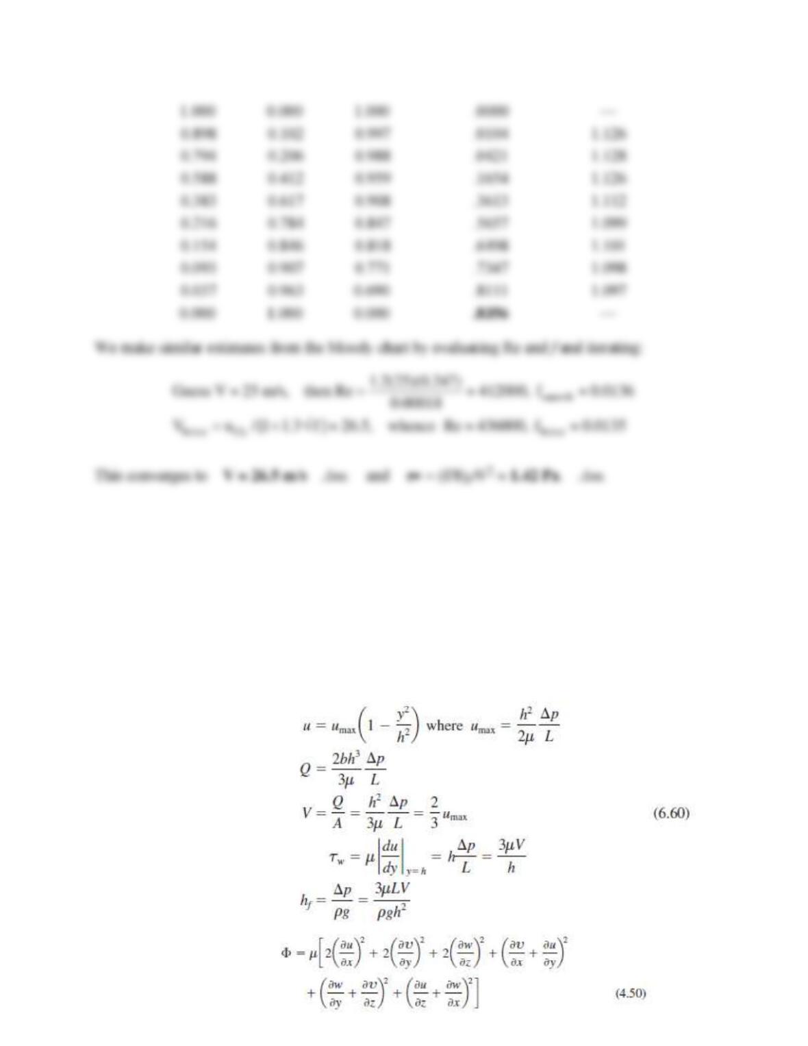
The centerline velocity uCL was 30.5 m/s. Determine (a) the average velocity by numerical
integration and (b) the wall shear stress from the log law approximation. Compare with the
Moody chart and with Eq. (6.43).
Solution 6.C6
For air at 20C, take
= 1.2 kg/m3 and
= 0.00018 kg/ms. The average velocity is defined by
the (dimensionless) integral
R1
2
CL CL
00
1 V u r
V u(2 r)dr, or: 2 d , where
u u R
R
= = =
Problem 6.C7
Consider energy exchange in fully-developed laminar flow between parallel plates, as in
Eq. (6.60). Let the pressure drop over a length L be p. Calculate the rate of work done by this
pressure drop on the fluid in the region (0 x L, −h y +h) and compare with the integrated
energy dissipated due to the viscous function from Eq. (4.50) over this same region. The two
should be equal. Explain why this is so. Can you relate the viscous drag force and the wall shear
stress to this energy result?
Solution 6.C7
From Eq. (6.63), the velocity profile between the plates is parabolic:
22
2
31 where is the average velocity
23
y h p
u V V L
h
= − =
Problem 6.C8
This text has presented the traditional correlations for turbulent smooth-wall friction factor,
Eq. (6.38), and the law-of-the-wall, Eq. (6.28). Recently, groups at Princeton and Oregon
[56] have made new friction measurements and suggest the following smooth-wall friction law:
In earlier work, they also report that better values for the constants
and B in the log-law,
Eq. (6.28), are
0.421 0.002 and B 5.62 0.08. (a) Calculate a few values of f in the
range 1E4 ReD 1E8 and see how the two formulas differ. (b) Read Ref. 56 and briefly check
the five papers in its bibliography. Report to the class on the general results of this work.
10
11.930log ( Re ) 0.537
Df
f=−
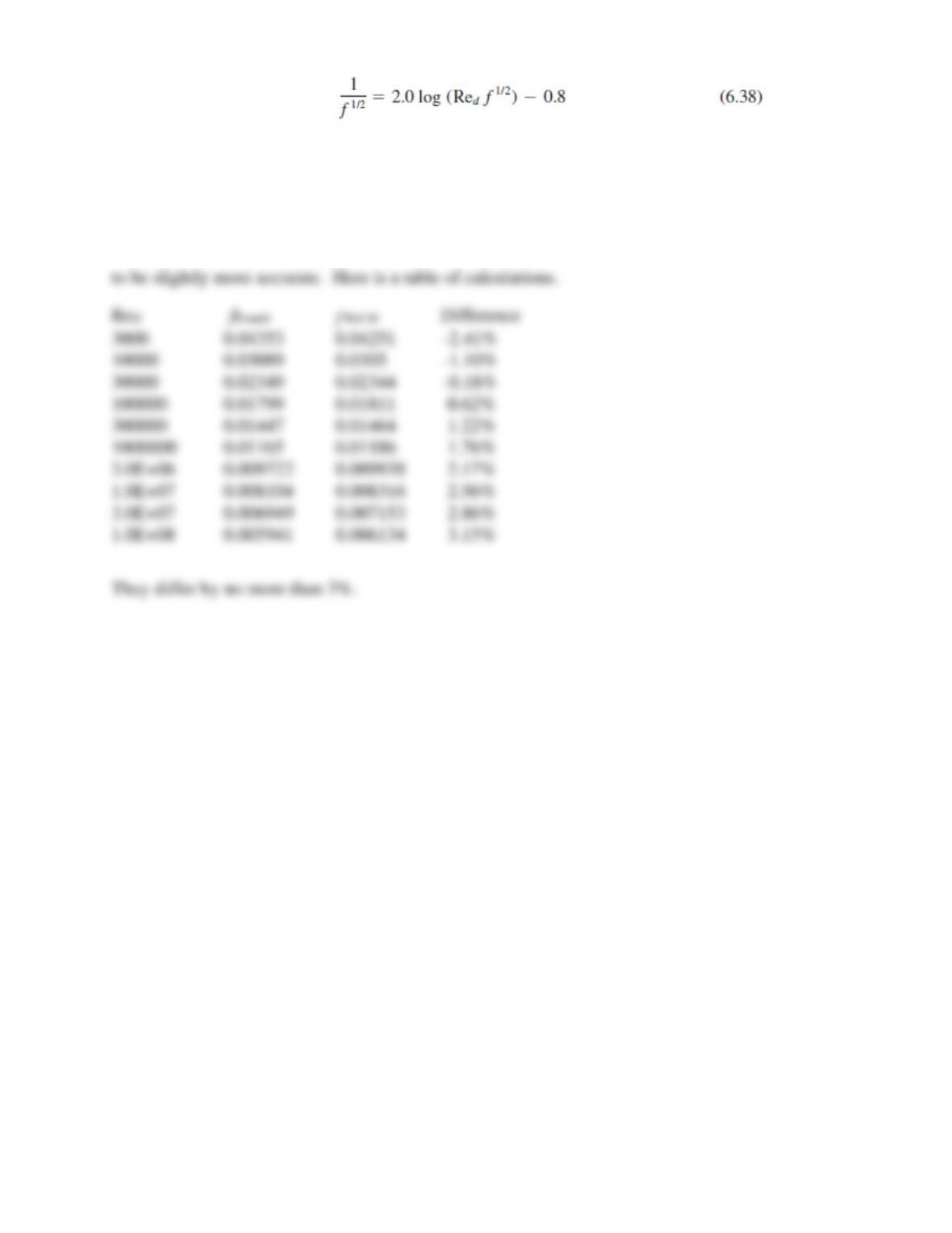
Solution 6.C8
The two formulas are practically identical except as the Reynolds number is very high or very
low. The new formula was fit to new, and extensive, friction data in Ref. 56 and can thus be said
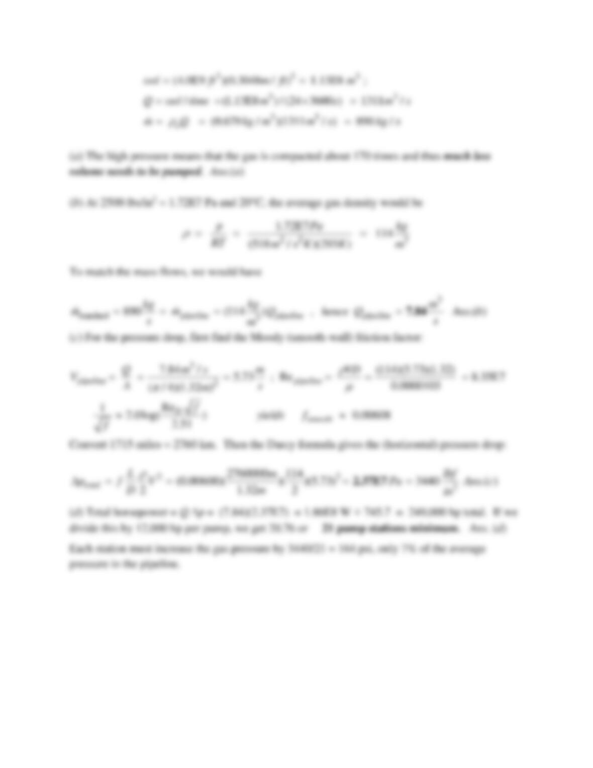
Problem 6.C9
A pipeline has been proposed to carry natural gas 1715 miles from Alaska’s North Slope to
Calgary, Alberta, Canada. The (assumed smooth) pipe diameter will be 52 inches. The gas will
be at high pressure, averaging 2500 lbs/in2. (a) Why? The proposed flow rate is 4 billion cubic
feet per day at sea-level conditions. (b) What volume flow rate, at 20C, would carry the same
mass at the high pressure? (c) If natural gas is assumed to be methane (CH4), what is the total
pressure drop? (d) If each pumping station can deliver 12,000 hp to the flow, how many stations
are needed?
Solution 6.C9
From Table A.4, for CH4, R = 518 m2/(s2-K) and
= 1.03E-5 kg/m-s. Sea-level density is
o = p/RT = 101350/[518(288)] = 0.679 kg/m3. The proposed mass flow rate is
Problem 6.W1
In fully developed straight-duct flow, the velocity profiles do not change (why?), but the pressure
drops along the pipe axis. Thus there is pressure work done on the fluid. If, say, the pipe is
insulated from heat loss, where does this energy go? Make a thermodynamic analysis of the pipe
flow.
Solution 6.W1
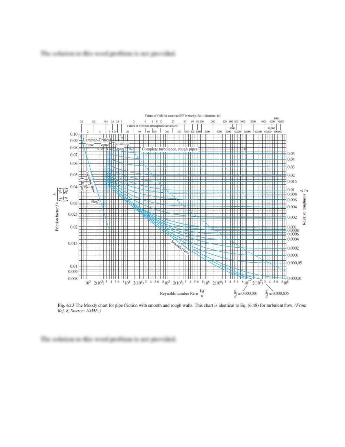
Problem 6.W2
From the Moody chart (Fig. 6.13), rough surfaces, such as sand grains or ragged machining, do
not affect laminar flow. Can you explain why? They do affect turbulent flow. Can you develop,
or suggest, an analytical–physical model of turbulent flow near a rough surface that might be
used to predict the known increase in pressure drop?
Solution 6.W2
Problem 6.W3
Differentiation of the laminar pipe flow solution, Eq. (6.40), shows that the fluid shear stress τ(r)
varies linearly from zero at the axis to τw at the wall. It is claimed that this is also true, at least in
the time mean, for fully developed turbulent flow. Can you verify this claim analytically?
Solution 6.W3
Problem 6.W4
A porous medium consists of many tiny tortuous passages, and Reynolds numbers based on pore
size are usually very low, of order unity. In 1856 H. Darcy proposed that the pressure gradient in
a porous medium was directly proportional to the volume-averaged velocity V of the fluid:
pK
= − V
where K is termed the permeability of the medium. This is now called Darcy’s law of porous
flow. Can you make a Poiseuille flow model of porous-media flow that verifies Darcy’s law?
Meanwhile, as the Reynolds number increases, so that VK1/2/ν > 1, the pressure drop becomes
nonlinear, as was shown experimentally by P. H. Forscheimer as early as 1782. The flow is still
decidedly laminar, yet the pressure gradient is quadratic:
Darcy-Forscheimer lawp C V
K
= − −
VV
where C is an empirical constant. Can you explain the reason for this nonlinear behavior?
Solution 6.W4
Problem 6.1
An engineer claims that flow of SAE 30W oil, at 20C, through a 5-cm-diameter smooth pipe at
1 million N/h, is laminar. Do you agree? A million newtons is a lot, so this sounds like an
awfully high flow rate.
Solution 6.1
For SAE 30W oil at 20C (Table A.3), take
= 891 kg/m3 and
= 0.29 kg/m-s. Convert the
weight flow rate to volume flow rate in SI units:

Problem 6.2
The present pumping rate of crude oil through the Alaska Pipeline, with an ID of 48 in, is
550,000 barrels per day (1 barrel is 42 U. S. gallons). (a) Is this a turbulent flow? (b) What
would be the maximum rate if the flow were constrained to be laminar? Assume that Alaskan oil
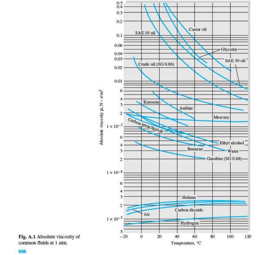
fits Fig. A.1 of the Appendix at 60ºC.
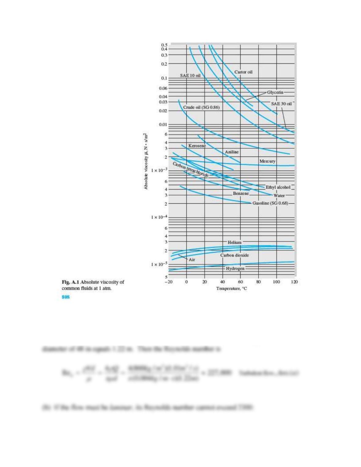
Solution 6.2
From Fig. A.1 of the Appendix, for crude oil at 60ºC, ρ = (SG)ρwater = 0.86(1000) = 860 kg/m3,
and μ ≈ 0.004 kg/m∙s. (a) Convert 550,000 barrels per day to 1.01 m3/s (Appendix C) and a
Problem 6.3
The Keystone Pipeline in the chapter opener photo has a maximum proposed flow rate of
1.3 million barrels of crude oil per day. Estimate the Reynolds number and whether the flow is
laminar. Assume that Keystone crude oil fits Fig. A.1 of the Appendix at 40ºC.
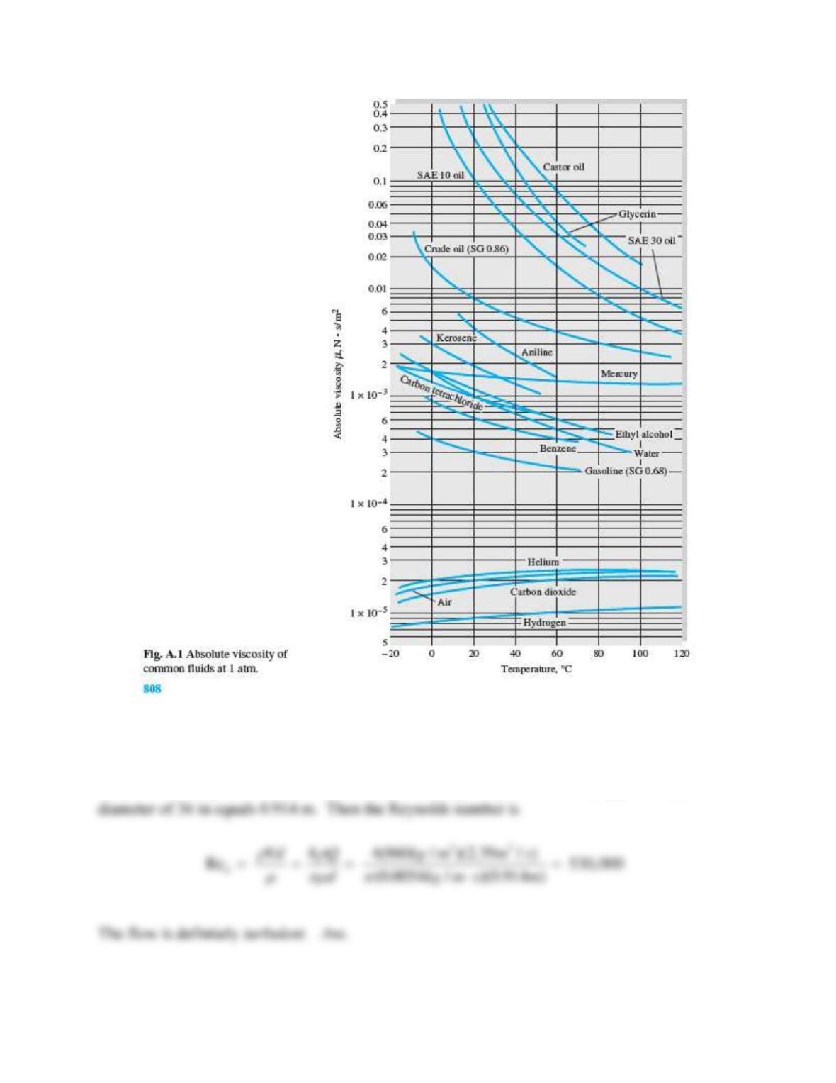
Solution 6.3
From Fig. A.1 of the Appendix, for crude oil at 40ºC, ρ = (SG)ρwater = 0.86(1000) = 860 kg/m3,
and μ ≈ 0.0054 kg/m·s. (a) Convert 1,300,000 barrels per day to 2.39 m3/s (Appendix C) and a
Problem 6.4
For flow of SAE 30W oil through a 5-cm-diameter pipe, from Fig. A.1, for what flow rate in
m3/h would we expect transition to turbulence at (a) 20C and (b) 100C?
Solution 6.4
For SAE 30W oil take
3
891 kg/m
=
and take
= 0.29 kg/ms at 20C (Table A.3) and 0.01 kg/m-s
at 100C (Fig A.1). Write the critical Reynolds number in terms of flow rate Q:
Problem 6.5
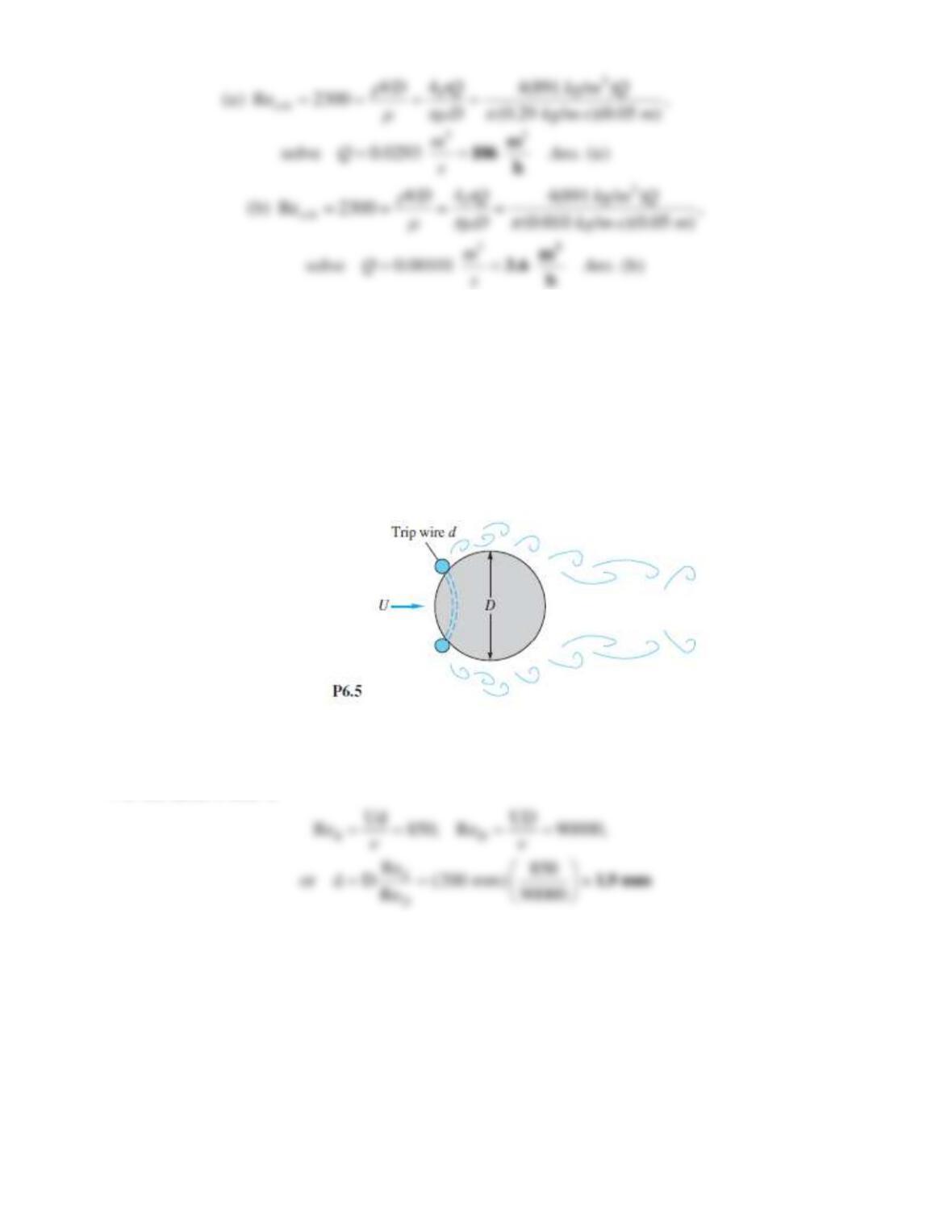
In flow past a body or wall, early transition to turbulence can be induced by placing a trip wire
on the wall across the flow, as in Fig. P6.5. If the trip wire in Fig. P6.5 is placed where the local
velocity is U, it will trigger turbulence if Ud/
= 850, where d is the wire diameter [3, p.388]. If the
sphere diameter is 20 cm and transition is observed at ReD = 90,000, what is the diameter of the
trip wire in mm?
Solution 6.5
For the same U and
,
Problem 6.6
For flow of a uniform stream parallel to a sharp flat plate, transition to a turbulent boundary layer
on the plate may occur at Rex =
Ux/
1E6, where U is the approach velocity and x is distance
along the plate. If U = 2.5 m/s, determine the distance x for the following fluids at 20C and
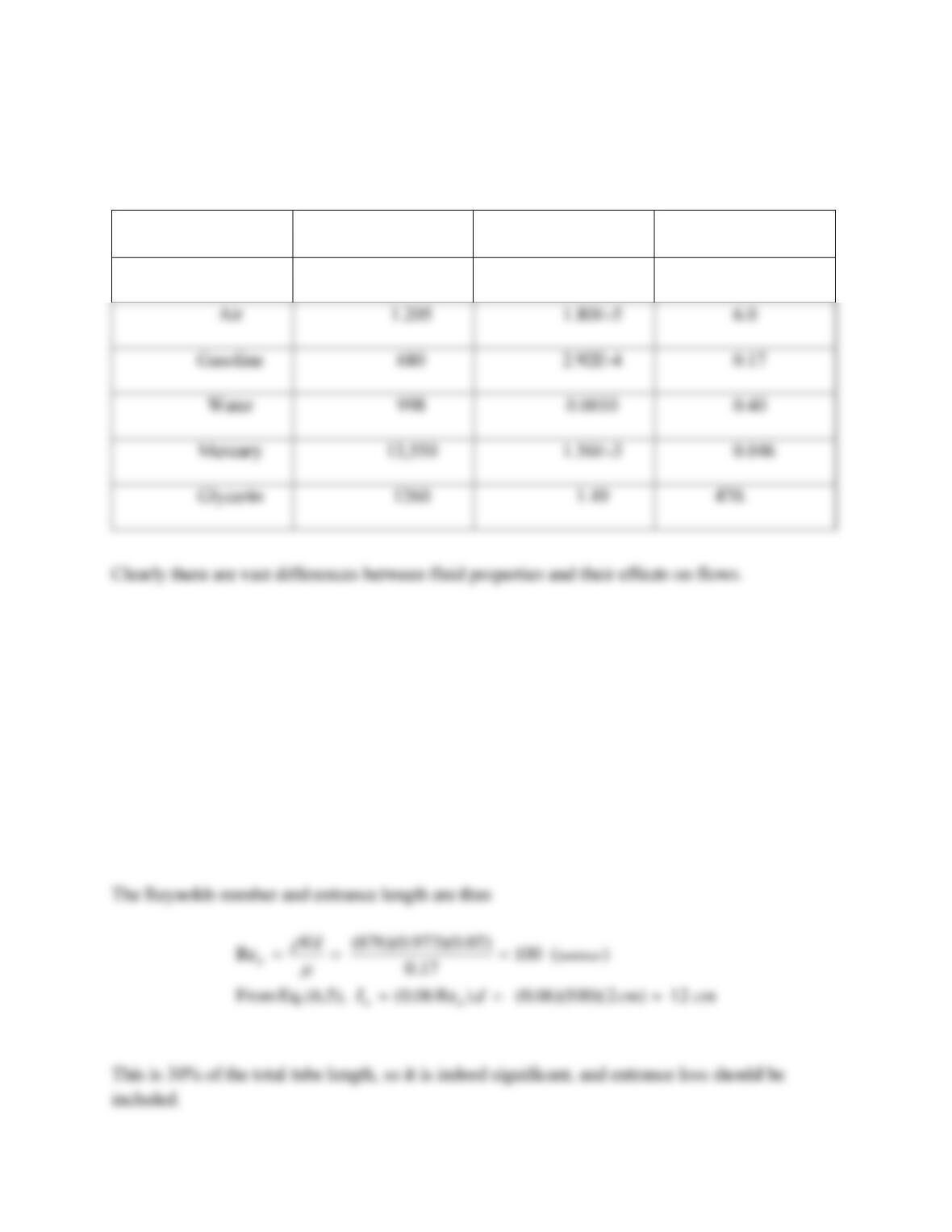
1 atm: (a) hydrogen; (b) air; (c) gasoline; (d) water; (e) mercury; and (f) glycerin.
Solution 6.6
We are to calculate x = (Rex)(
)/(
U) = (1E6)(
)/[
(2.5m/s)]. Make a table:
FLUID
– kg/m3
– kg/m-s
x – meters
Hydrogen
0.00839
9.05E-5
43.
Problem 6.7
SAE 10W30 oil at 20ºC flows from a tank into a 2 cm-diameter tube 40 cm long. The flow rate
is 1.1 m3/hr. Is the entrance length region a significant part of this tube flow?
Solution 6.7
From Table A.4, for SAE 10W30 oil, read ρ = 876 kg/m3 and μ = 0.17 kg/m∙s. The flow rate is
(1.1 m3/hr )/(3600 s/hr) = 0.0003056 m3/s, and the average velocity is V = 4Q/(πd2) = 0.973 m/s.
2.92E-4
0.17
0.40
470.