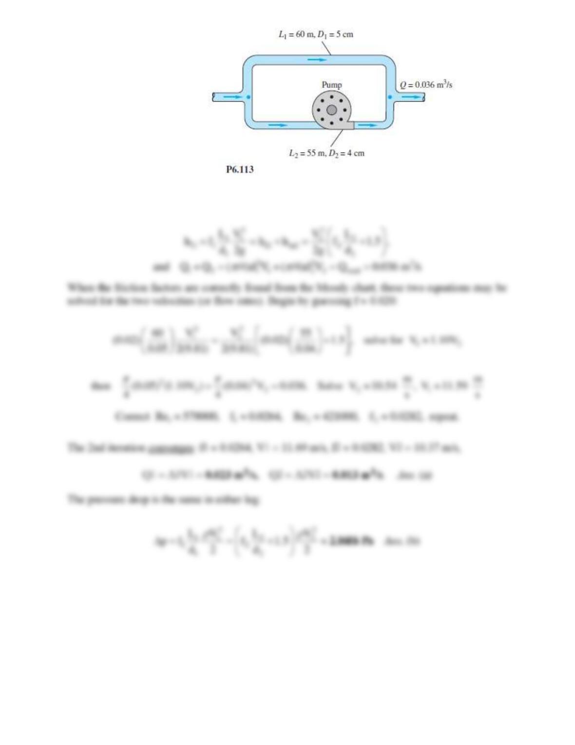
Solution 6.113
For water at 20C, take
= 998 kg/m3 and
= 0.001 kg/ms. For galvanized iron,
= 0.15 mm.
Assume turbulent flow, with p the same for each leg:
Problem 6.114*
A blower supplies standard air to a plenum that feeds two horizontal square sheet-metal ducts
with sharp-edged entrances. One duct is 100 ft long, with a cross-section 6 in by 6 in. The
second duct is 200 ft long. Each duct exhausts to the atmosphere. When the plenum pressure is
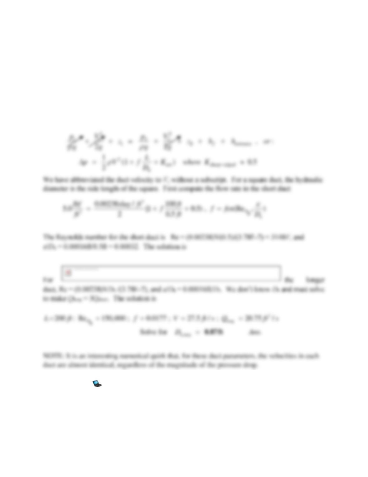
5.0 lbf/ft2 (gage), the volume flow in the longer duct is three times the flow in the shorter duct.
Estimate both volume flows and the cross-section size of the longer duct.
Solution 6.114*
For standard air, in BG units, take
= 0.00238 slug/ft3 and
= 3.78E-7 slug/ft-sec. For sheet
metal, take
= 0.00016 ft. The energy equation for this case is
Problem 6.115
In Fig. P6.115 all pipes are 8-cm-diameter cast iron. Determine the flow rate from reservoir (1) if
valve C is (a) closed; and (b) open, with K = 0.5.
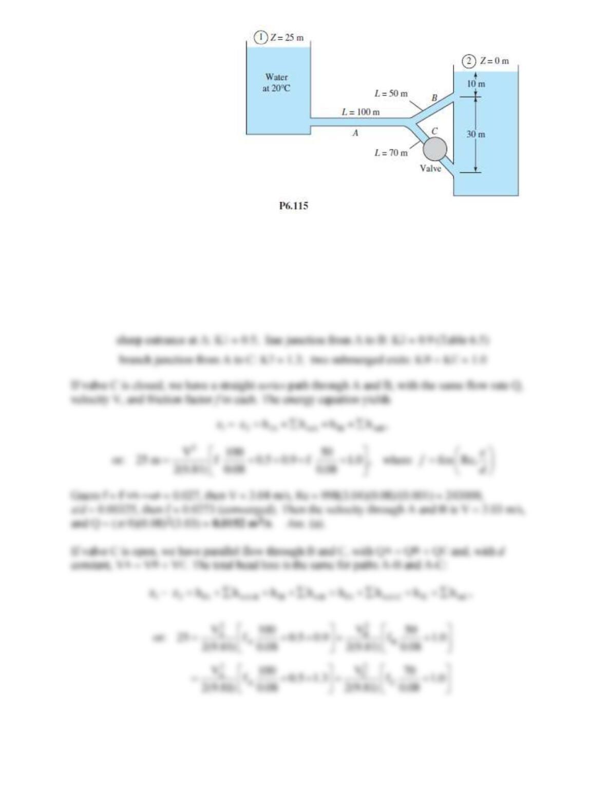
Solution 6.115
For water at 20C, take
= 998 kg/m3 and
= 0.001 kg/ms. For cast iron,
0.26 mm, hence
/d = 0.26/80 0.00325 for all three pipes. Note p1 = p2, V1 = V2 0. These are long pipes, but
we might wish to account for minor losses anyway:
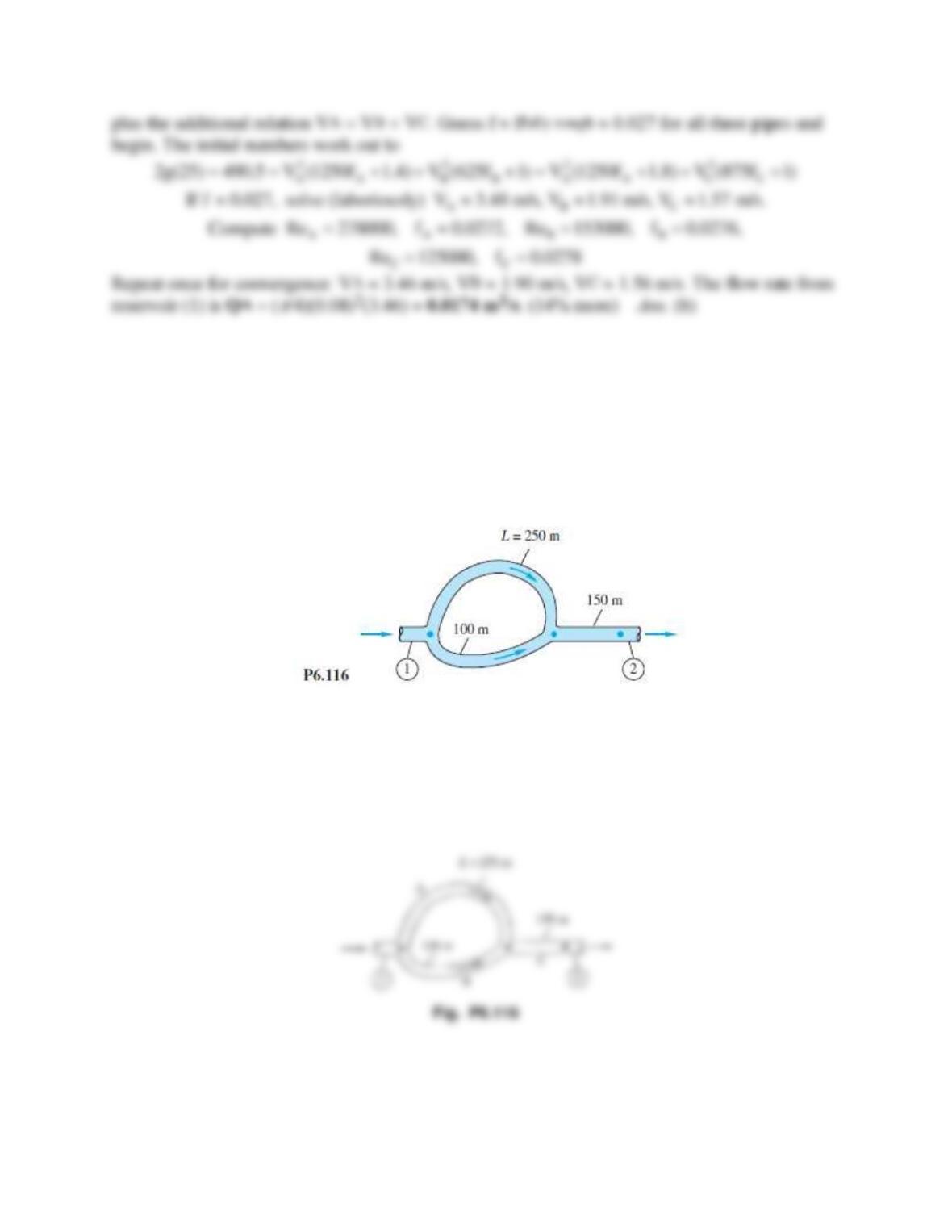
Problem 6.116
For the series-parallel system of Fig. P6.116, all pipes are 8-cm-diameter asphalted cast iron. If
the total pressure drop p1 − p2 = 750 kPa, find the resulting flow rate Q m3/h for water at 20C.
Neglect minor losses.
Solution 6.116
For water at 20C, take
= 998 kg/m3 and
= 0.001 kg/ms. For asphalted cast iron,
0.12 mm,
hence
/d = 0.12/80 0.0015 for all three pipes. The head loss is the same through AC and BC:

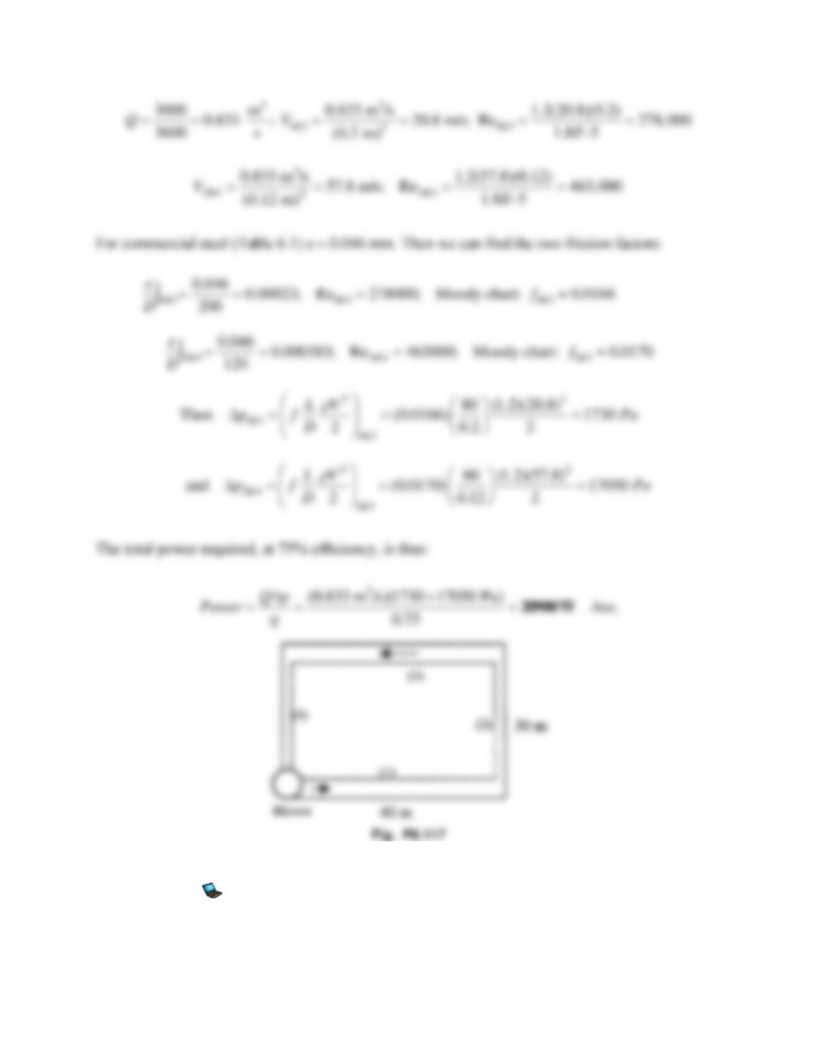
Problem 6.117
A blower delivers air at 3000 m3/h to the duct circuit in Fig. P6.117. Each duct is commercial
steel and of square cross-section, with side lengths a1 = a3 = 20 cm and a2 = a4 = 12 cm.
Assuming sea-level air conditions, estimate the power required if the blower has an efficiency of
75 percent. Neglect minor losses.
Solution 6.117
For air take
= 1.2 kg/m3 and
= 1.8E−5 kg/ms. Establish conditions in each duct:
Problem 6.118
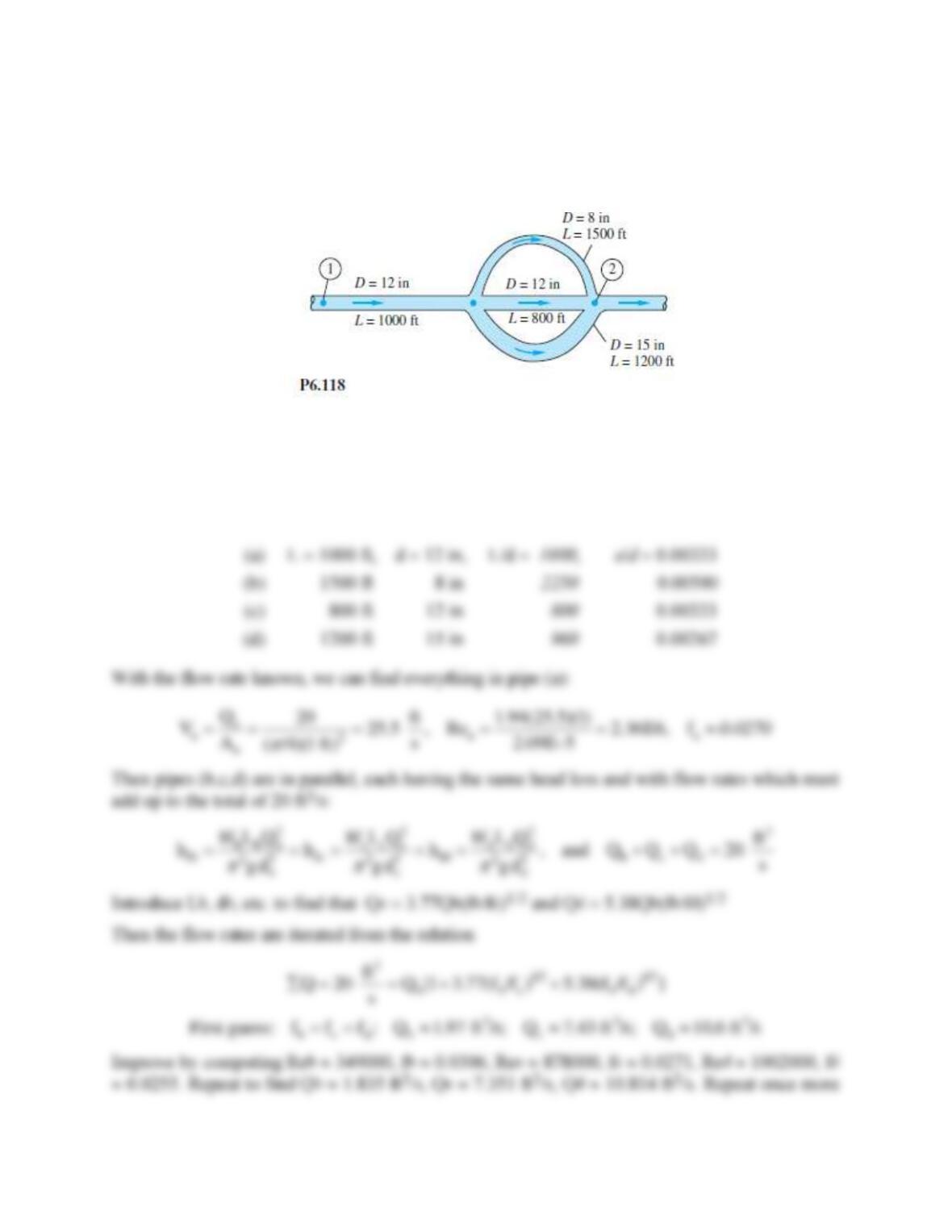
For the piping system of Fig. P6.118, all pipes are concrete with a roughness of 0.04 inch.
Neglecting minor losses, compute the overall pressure drop p1 − p2 in lbf/in2. The flow rate is
20 ft3/s of water at 20C.
Solution 6.118
For water at 20C, take
= 1.94 slug/ft3 and
= 2.09E−5 slug/fts. Since the pipes are all
different make a little table of their respective L/d and
/d:
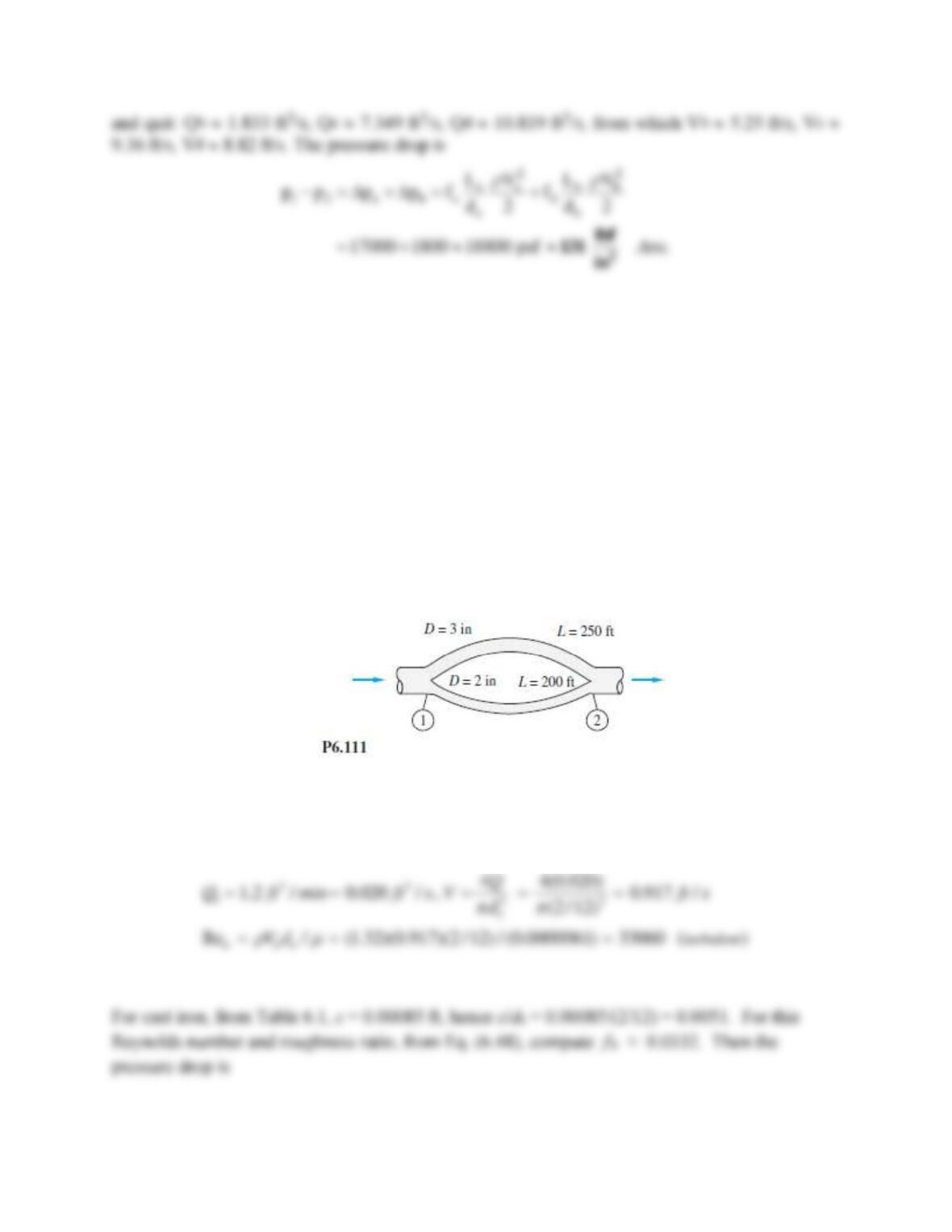
Problem 6.119
For the piping system of Prob. P6.111, let the fluid be gasoline at 20ºC, with both pipes cast iron.
If the flow rate in the 2-in pipe (b) is 1.2 ft3/min, estimate the flow rate in the 3-in pipe (a), in
ft3/min.
Problem 6.111
For the parallel-pipe system of Fig. P6.111, each pipe is cast iron, and the pressure drop
p1 − p2 = 3 lbf/in2. Compute the total flow rate between 1 and 2 if the fluid is SAE 10 oil at
20C.
Solution 6.119
For gasoline at 20ºC, take ρ = 1.32 slug/ft3, and μ = 6.1E-6 slug/ft·s. For pipe b, find the velocity
and Reynolds number:
Problem 6.120
Three cast-iron pipes are laid in parallel with these dimensions:
Pipe 1:
L1 = 800 m
d1 = 12 cm
Pipe 2:
L2 = 600 m
d2 = 8 cm
Pipe 3:
L3 = 900 m
d3 = 10 cm
The total flow rate is 200 m3/h of water at 20C. Determine (a) the flow rate in each pipe; and
(b) the pressure drop across the system.
Solution 6.120
For water at 20C, take
= 998 kg/m3 and
= 0.001 kg/ms. For cast iron,
= 0.26 mm. Then,
/d1
= 0.00217,
/d2 = 0.00325, and
/d3 = 0.0026. The head losses are the same for each pipe, and the
flow rates add:
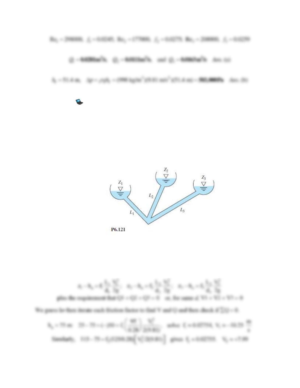
Problem 6.121
Consider the three-reservoir system of Fig. P6.121 with the following data:
L1 = 95 m
L2 = 125 m
L3 = 160 m
z1 = 25 m
z2 = 115 m
z3 = 85 m
All pipes are 28-cm-diameter unfinished concrete (
= 1 mm). Compute the steady flow rate in all
pipes for water at 20C.
Solution 6.121
For water at 20C, take
= 998 kg/m3 and
= 0.001 kg/ms. All pipes have
/d = 1/280 = 0.00357. Let the intersection be “a.” The head loss at “a” is desired:
Problem 6.122
Modify Prob. P6.121 as follows: Reduce the diameter to 15 cm (with ε = 1 mm), and compute
the flow rates for water at 20°C. These flow rates distribute in nearly the same manner as in
Prob. P6.121 but are about 5.2 times lower. Can you explain this difference?
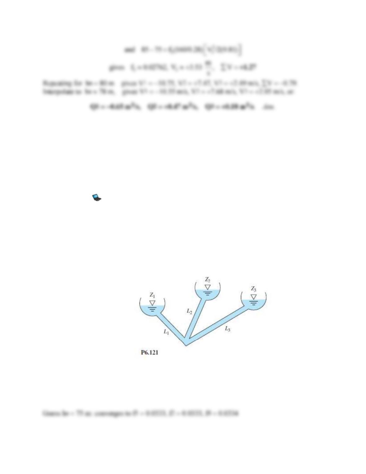
Problem 6.121
Consider the three-reservoir system of Fig. P6.121 with the following data:
L1 = 95 m
L2 = 125 m
L3 = 160 m
z1 = 25 m
z2 = 115 m
z3 = 85 m
All pipes are 28-cm-diameter unfinished concrete (
= 1 mm). Compute the steady flow rate in all
pipes for water at 20C.
Solution 6.122
The roughness ratio increases to
/d = 1/150 = 0.00667, and all L/d’s increase.
Problem 6.123
Modify Prob. P6.121 as follows: All data are the same except that z3 is unknown. Find the value
of z3 for which the flow rate in pipe 3 is 0.2 m3/s toward the junction. (This problem requires
iteration and is best suited to a computer.)
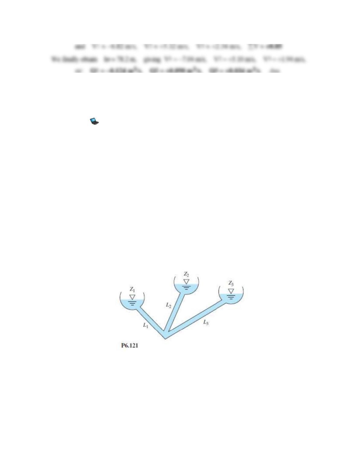
Problem 6.121
Consider the three-reservoir system of Fig. P6.121 with the following data:
L1 = 95 m
L2 = 125 m
L3 = 160 m
z1 = 25 m
z2 = 115 m
z3 = 85 m
All pipes are 28-cm-diameter unfinished concrete (
= 1 mm). Compute the steady flow rate in all
pipes for water at 20C.
Solution 6.123
For water at 20C, take
= 998 kg/m3 and
= 0.001 kg/ms. All pipes have
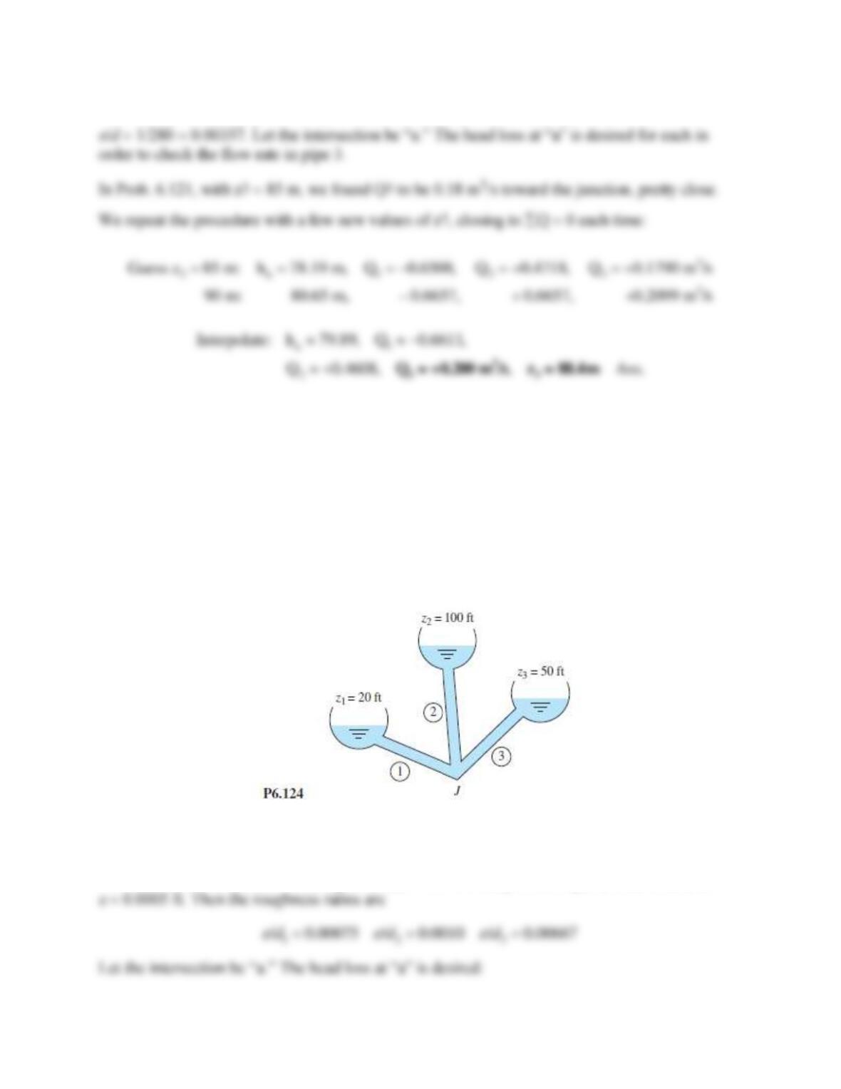
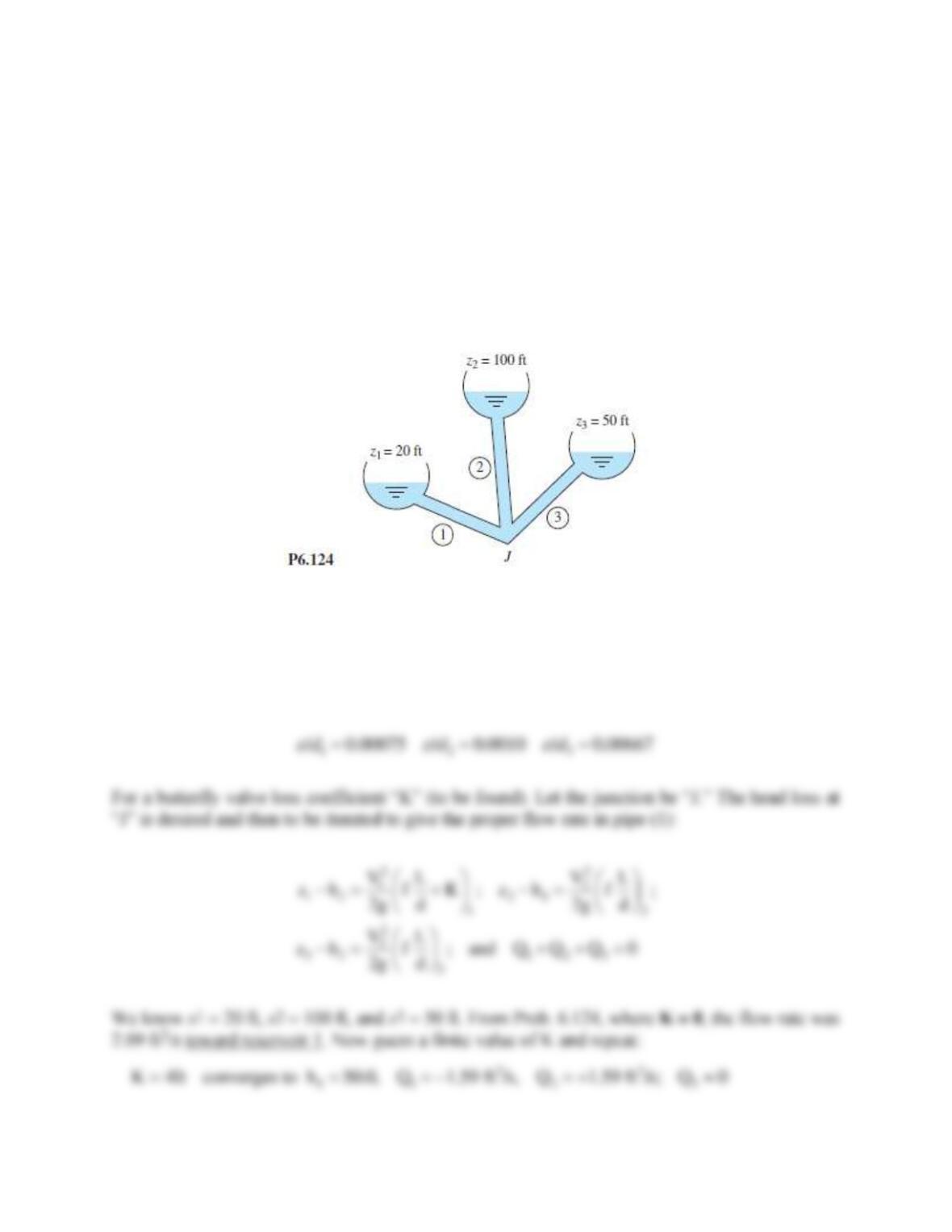
Problem 6.124
The three-reservoir system in Fig. P6.124 delivers water at 20C. The system data are as follows:
D1 = 8 in
D2 = 6 in
D3 = 9 in
L1 =1800 ft
L2 = 1200 ft
L3 = 1600 ft
All pipes are galvanized iron. Compute the flow rate in all pipes.
Solution 6.124
For water at 20C, take
= 1.94 slug/ft3 and
= 2.09E−5 slug/fts. For galvanized iron, take
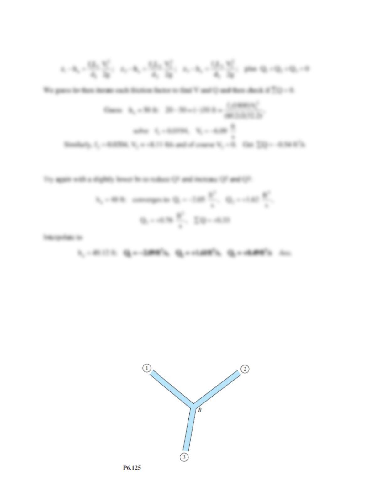
Problem 6.125
Suppose that the three cast-iron pipes in Prob. 6.120 are instead connected to meet smoothly at a
point B, as shown in Fig. P6.125. The inlet pressures in each pipe are: p1 = 200 kPa;
p2 = 160 kPa; p3 = 100 kPa. The fluid is water at 20C. Neglect minor losses. Estimate the flow
rate in each pipe and whether it is toward or away from point B.
Solution 6.125
For water take
= 998 kg/m3 and
= 0.001 kg/ms. The pressure at point B must be a known
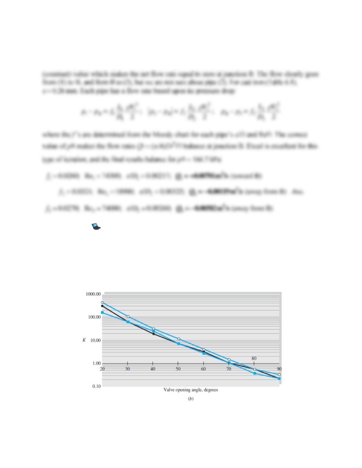
Problem 6.126
Modify Prob. 6.124 as follows. Let all data be the same except that pipe 1 is fitted with a
butterfly valve (Fig. 6.19b). Estimate the proper valve opening angle (in degrees) for the flow
rate through pipe 1 to be reduced to 1.5 ft3/s toward reservoir 1. (This problem requires iteration
and is best suited to a computer.)
Fig. 6.19b
Problem 6.124
The three-reservoir system in Fig. P6.124 delivers water at 20C. The system data are as follows:
D1 = 8 in
D2 = 6 in
D3 = 9 in
L1 =1800 ft
L2 = 1200 ft
L3 = 1600 ft
All pipes are galvanized iron. Compute the flow rate in all pipes.
Solution 6.126
For water at 20C, take
= 1.94 slug/ft3 and
= 2.09E−4 slug/fts. For galvanized iron, take
= 0.0005 ft. Then the roughness ratios are