Solution 6.96
For air at 20C and 1 atm, take
= 1.20 kg/m3 and
= 1.8E-5 kg/m-s. The hydraulic diameter
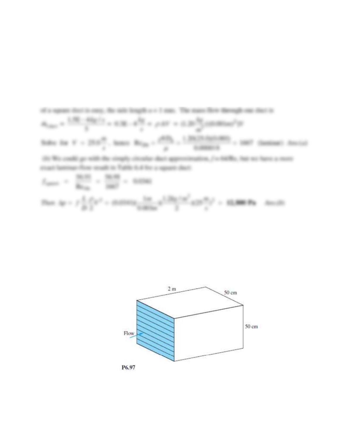
Problem 6.97
A heat exchanger consists of multiple parallel–plate passages, as shown in Fig. P6.97. The available
pressure drop is 2 kPa, and the fluid is water at 20C. If the desired total flow rate is 900 m3/h,
estimate the appropriate number of passages. The plate walls are hydraulically smooth.
Neglect minor losses.
Solution 6.97
For water,
= 998 kg/m3 and
= 0.001 kg/ms. Unlike Prob. 6.88, here we expect turbulent
flow. If there are N passages, then b = 50 cm for all N and the passage thickness is H = 0.5 m/N.
The hydraulic diameter is Dh = 2H. The velocity in each passage is related to the pressure drop by
Eq. (6.58):
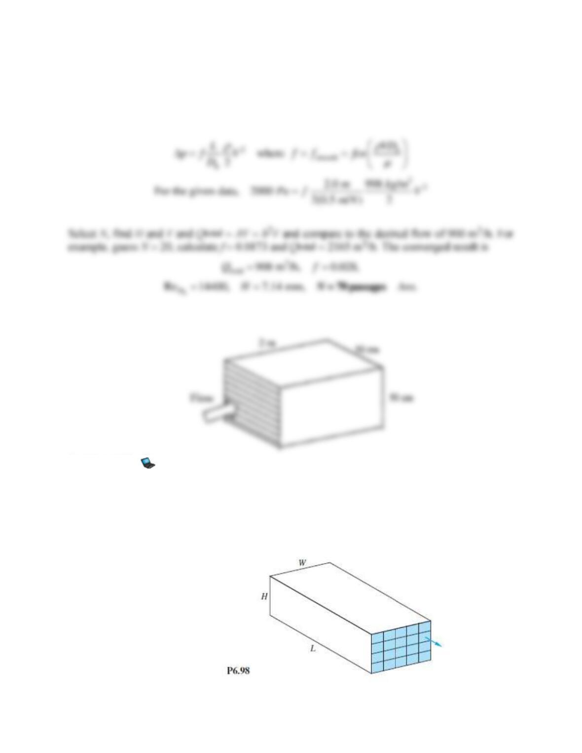
Problem 6.98
A rectangular heat exchanger is to be divided into smaller sections using sheets of commercial
steel 0.4 mm thick, as sketched in Fig. P6.98. The flow rate is 20 kg/s of water at 20C. Basic
dimensions are L = 1 m, W = 20 cm, and H = 10 cm. What is the proper number of square sections
if the overall pressure drop is to be no more than 1600 Pa?
Neglect minor losses.
Solution 6.98
For water at 20C, take
= 998 kg/m3 and
= 0.001 kg/ms. For commercial steel,
0.046 mm. Let the short side (10 cm) be divided into “J” squares. Then the long (20 cm) side
Problem 6.99
In Sec. 6.11 it was mentioned that Roman aqueduct customers obtained extra water by attaching
a diffuser to their pipe exits. Fig. P6.99 shows a simulation: a smooth inlet pipe, with and
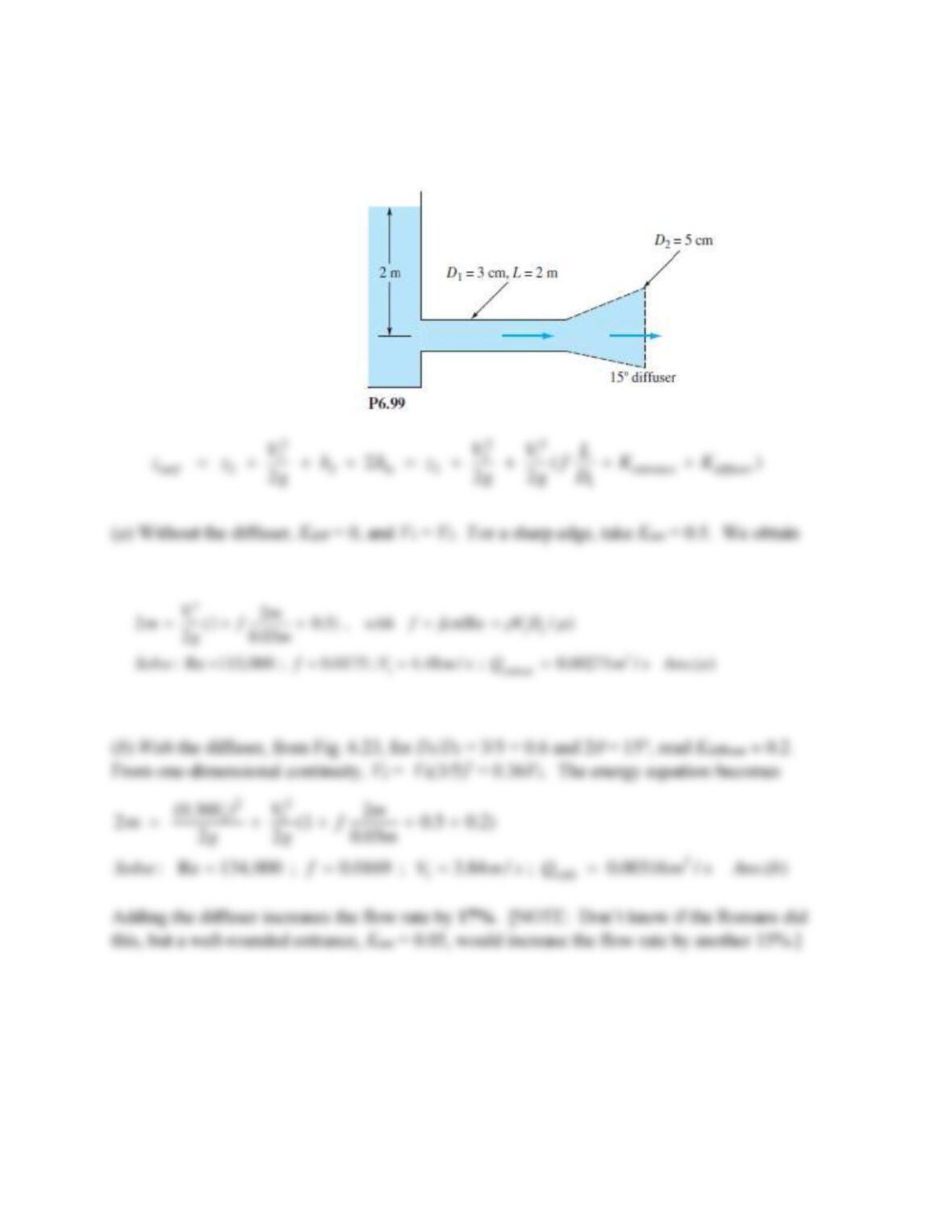
without a 15 diffuser expanding to a 5-cm-diameter exit. The pipe entrance is sharp-edged.
Calculate the flow rate (a) without, and (b) with the diffuser.
Neglect minor losses.
Solution 6.99
For water at 20C, take
= 998 kg/m3 and
= 0.001 kg/m-s. The energy equation between the
aqueduct surface and the pipe exit yields
Problem 6.100*
Modify Prob. P6.55 as follows. Assume a pump can deliver 3 kW to pump the water back up to
reservoir 1 from reservoir 2. Accounting for an open flanged globe valve and sharp-edged
entrance and exit, estimate the predicted flow rate, in m3/hr.
Minor losses are included.
Problem 6.55
The reservoirs in Fig. P6.55 contain water at 20C. If the pipe is smooth with L = 4500 m and
d = 4 cm, what will the flow rate in m3/h be for z = 100 m?
Neglect minor losses.
Solution 6.100
NOTE: IN PROBLEMS 6.100−6.110, MINOR LOSSES ARE INCLUDED.
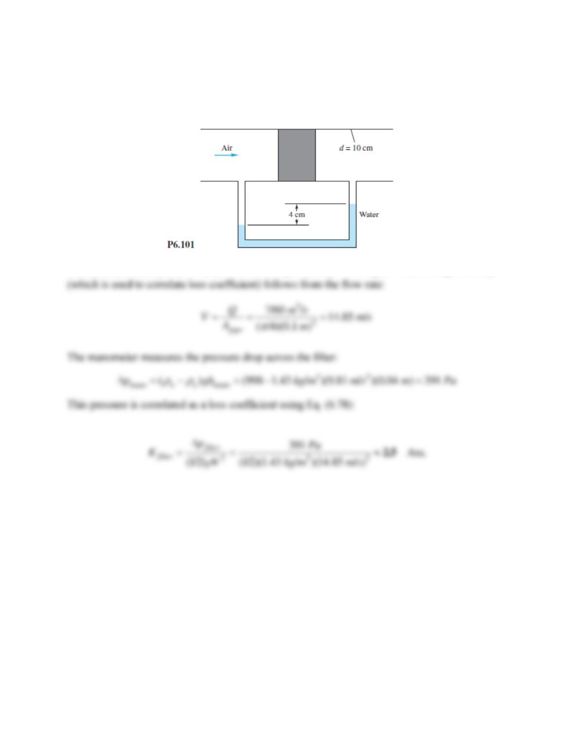
Problem 6.101
In Fig. P6.101 a thick filter is being tested for losses. The flow rate in the pipe is 7 m3/min, and
the upstream pressure is 120 kPa. The fluid is air at 20C. Using the water-manometer reading,
estimate the loss coefficient K of the filter.
Minor losses are included.
Solution 6.101
The upstream density is
air = p/(RT) = 120000/[287(293)] = 1.43 kg/m3. The average velocity V
Problem 6.102*
A 70 percent efficient pump delivers water at 20C from one reservoir to another 20 ft higher, as
in Fig. P6.102. The piping system consists of 60 ft of galvanized-iron 2-in pipe, a reentrant
entrance, two screwed 90 long-radius elbows, a screwed-open gate valve, and a sharp exit. What is
the input power required in horsepower with and without a 6 well-designed conical expansion added
to the exit? The flow rate is 0.4 ft3/s.
Minor losses are included.
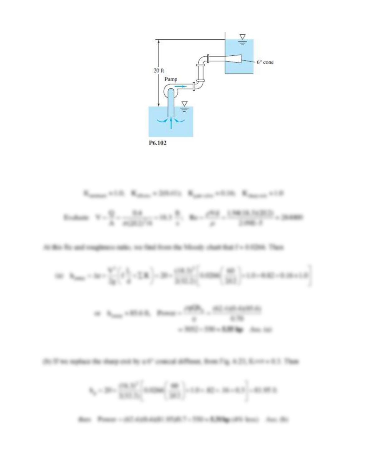
Solution 6.102
For water at 20C, take
= 1.94 slug/ft3 and
= 2.09E−5 slug/fts. For galvanized iron,
0.0005 ft,
whence
/d = 0.0005/(2/12 ft) 0.003. Without the 6 cone, the minor losses are:
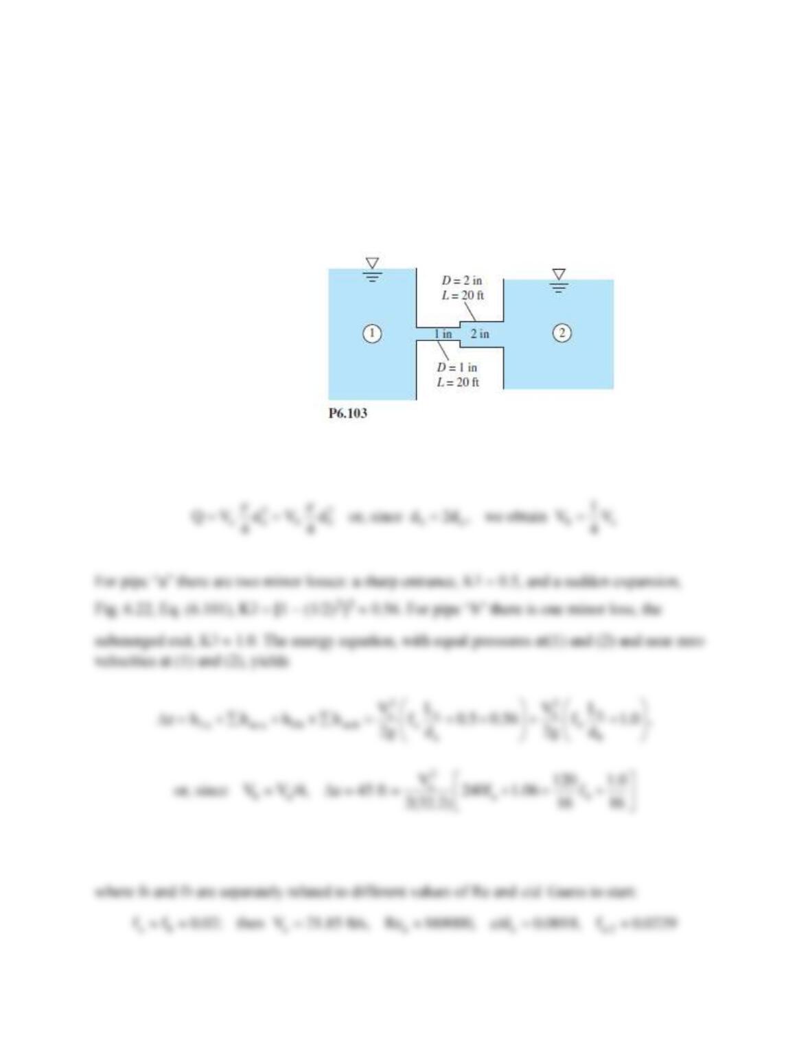
Problem 6.103
The reservoirs in Fig. P6.103 are connected by cast-iron pipes joined abruptly, with sharp-edged
entrance and exit. Including minor losses, estimate the flow of water at 20C if the surface of
reservoir 1 is 45 ft higher than that of reservoir 2.
Minor losses are included.
Solution 6.103
For water at 20C, take
= 1.94 slug/ft3 and
= 2.09E−5 slug/fts. Let “a” be the small pipe and
“b” the larger. For wrought iron,
0.00015 ft, whence
/da = 0.0018 and
/db = 0.0009. From
the continuity relation,
Problem 6.104
Consider a 20ºC flow at 2 m/s through a smooth 3-mm diameter microtube which consists of a
straight run of 10 cm, a long radius bend, and another straight run of 10 cm. Compute the total
pressure drop if the fluid is (a) water; and (b) ethylene glycol.
Minor losses are included.
Solution 6.104
(a) For water, take ρ = 998 kg/m3, and μ = 0.0010 kg/m·s. Compute the Reynolds number:
Problem 6.105
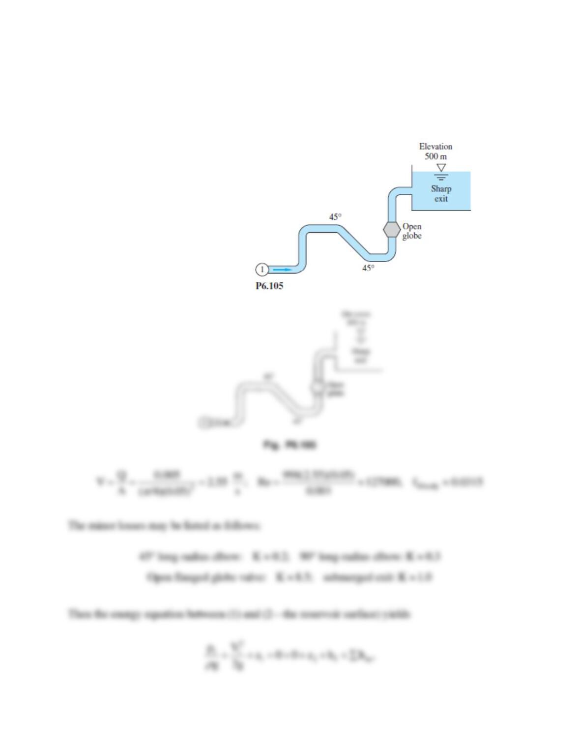
The system in Fig. P6.105 consists of 1200 m of 5 cm cast iron pipe, two 45 and four 90
flanged long-radius elbows, a fully open flanged globe valve, and a sharp exit into a reservoir. If
the elevation at point 1 is 400 m, what gage pressure is required at point 1 to deliver 0.005 m3/s
of water at 20C into the reservoir?
Minor losses are included.
Solution 6.105
For water at 20C, take
= 998 kg/m3 and
= 0.001 kg/ms. For cast iron, take
0.26 mm,
hence
/d = 0.0052. With the flow rate known, we can compute V, Re:
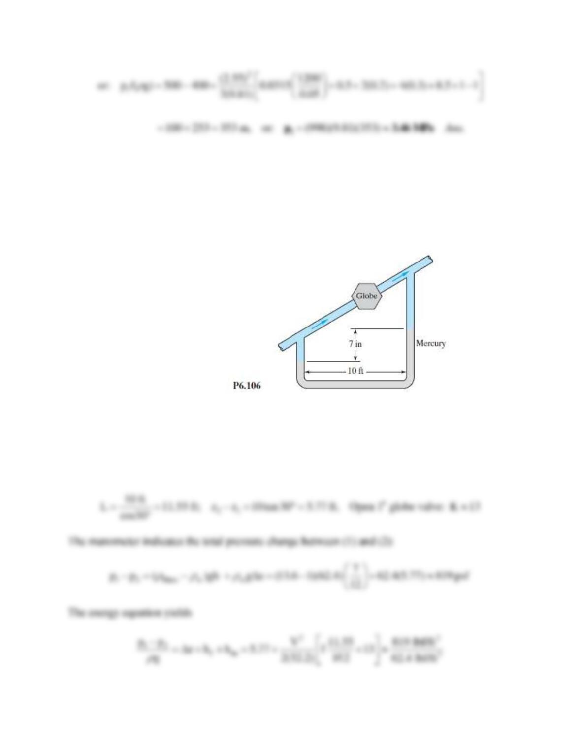
Problem 6.106
The water pipe in Fig. 6.106 slopes upward at 30. The pipe is 1-inch diameter and smooth. The
flanged globe valve is fully open. If the mercury manometer shows a 7-in deflection, what is
the flow rate in ft3/s?
Minor losses are included.
Solution 6.106
For water at 20C, take
= 1.94 slug/ft3 and
= 2.09E−5 slug/fts. The pipe length and elevation
change are
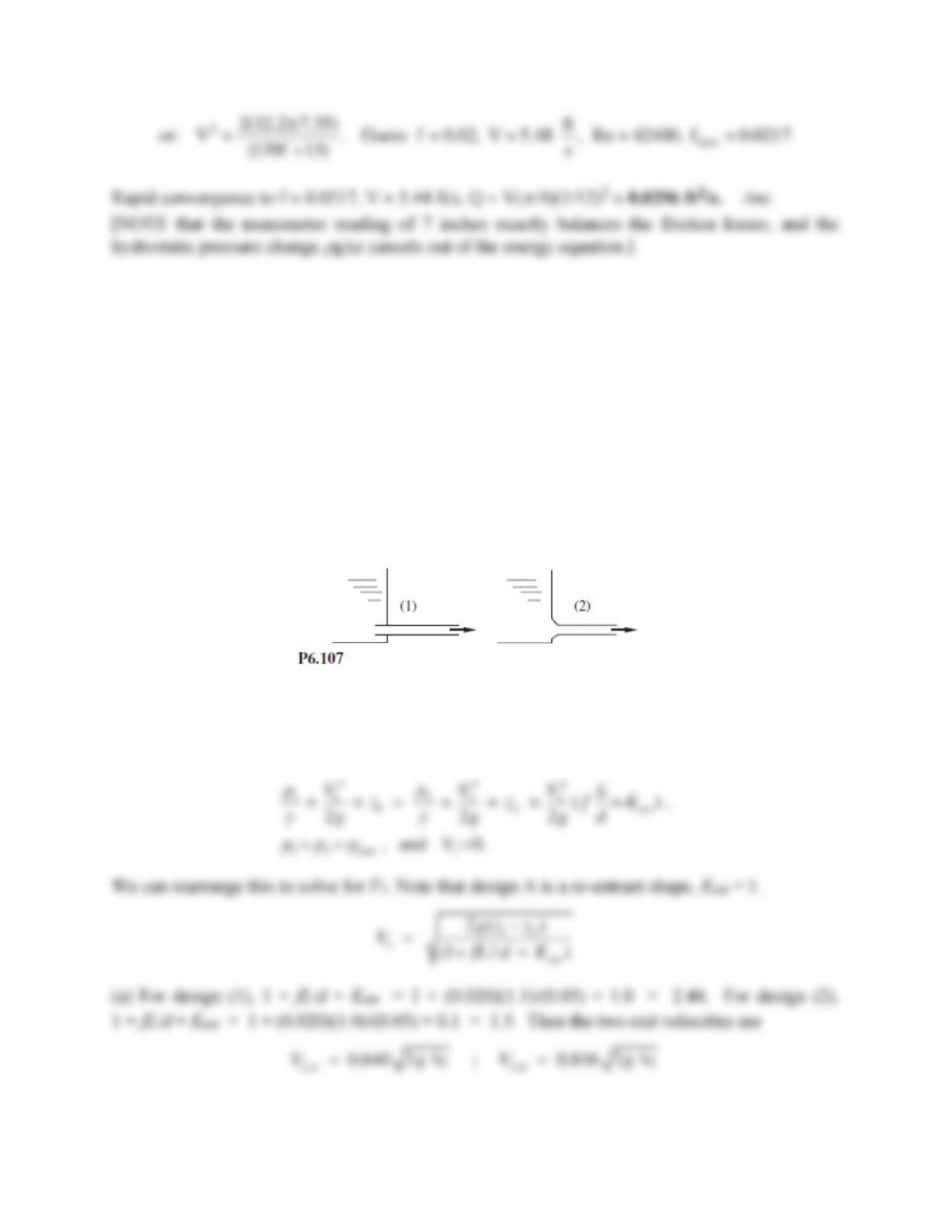
Problem 6.107*
A tank of water 4 m in diameter and 7 m deep is to be drained by a 5-cm diameter exit pipe at the
bottom, as in Fig. P6.107. In design (1), the pipe extends out for 1 m and into the tank for 10 cm.
In design (2), the interior pipe is removed and the entrance beveled, Fig. 6.21, so that K ≈ 0.1 in
the entrance. (a) An engineer claims that design (2) will drain 25% faster than design (1). Is this
claim true? (b) Estimate the time to drain of design (2), assuming f ≈ 0.020.
Minor losses are included.
Solution 6.107*
For water, take ρ = 998 kg/m3. We don’t need μ because f is given (for simplicity). Let 1 be the
tank surface and 2 be the exit jet. Then the energy equation is
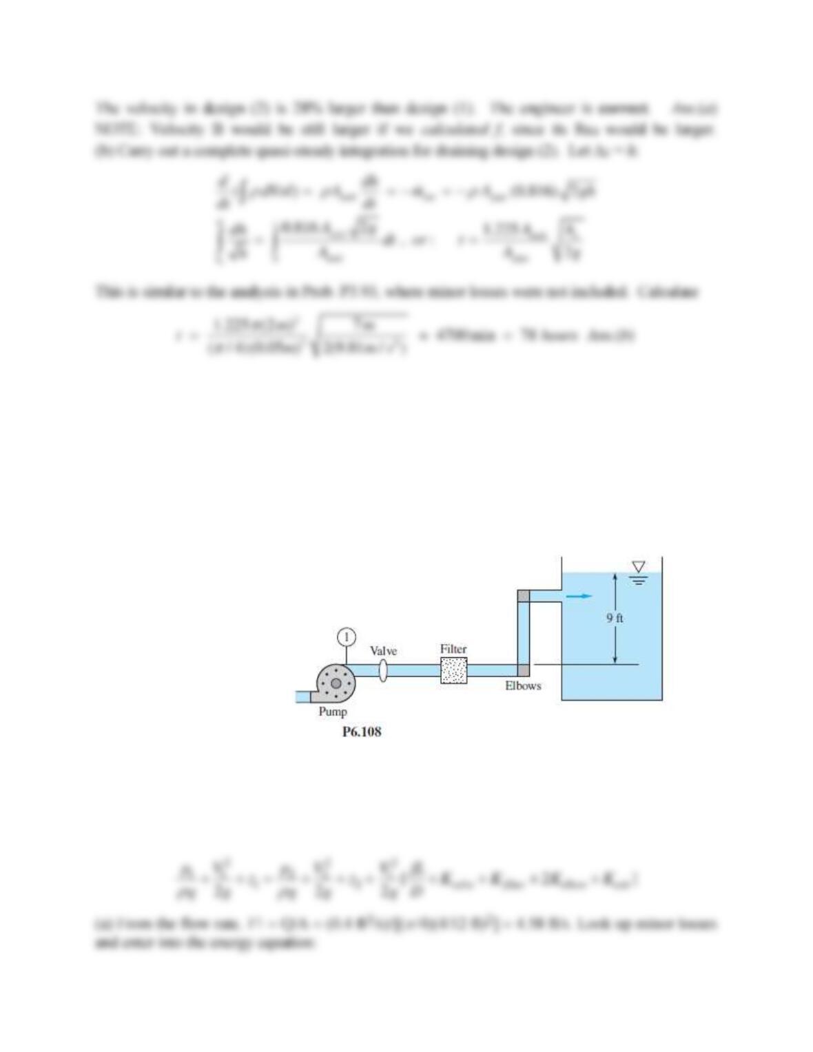
Problem 6.108
The water pump in Fig. P6.108 maintains a pressure of 6.5 psig at point 1. There is a filter, a
half-open disk valve, and two regular screwed elbows. There are 80 ft of 4–inch diameter
commercial steel pipe. (a) If the flow rate is 0.4 ft3/s, what is the loss coefficient of the filter?
(b) If the disk valve is wide open and Kfilter = 7, what is the resulting flow rate?
Minor losses are included.
Solution 6.108
For water, take
= 1.94 slug/ft3 and
= 2.09E−5 slug/fts. The energy equation is written from
point 1 to the surface of the tank:
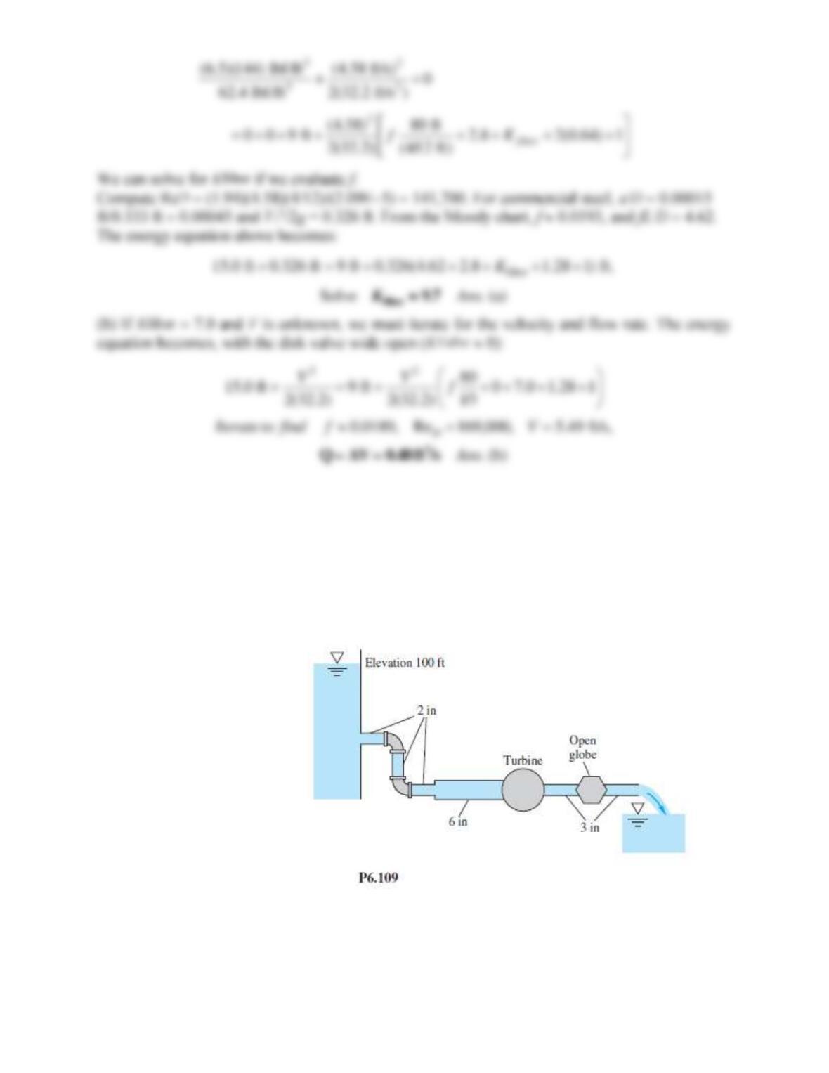
Problem 6.109
In Fig. P6.109 there are 125 ft of2-in pipe, 75 ft of 6-in pipe, and 150 ft of 3-in pipe, all cast iron.
There are three 90 elbows and an open globe valve, all flanged. If the exit elevation is zero,
what horsepower is extracted by the turbine when the flow rate is 0.16 ft3/s of water at 20C?
Minor losses are included.
Solution 6.109
For water at 20C, take
= 1.94 slug/ft3 and
= 2.09E−5 slug/fts. For cast iron,
0.00085 ft.
The 2, 6, and 3 pipes have, respectively,
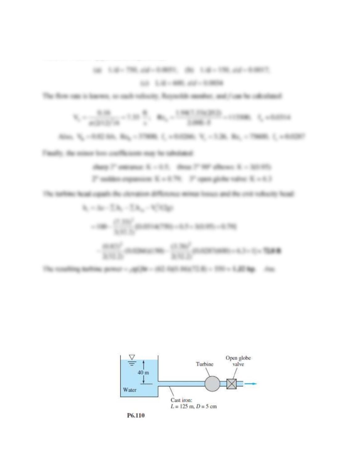
Problem 6.110
In Fig. P6.110 the pipe entrance is sharp-edged. If the flow rate is 0.004 m3/s, what power, in W,
is extracted by the turbine?
Minor losses are included.
Solution 6.110
For water at 20C, take
= 998 kg/m3 and
= 0.001 kg/ms. For cast iron,
0.26 mm, hence
/d = 0.26/50 0.0052. The minor loss coefficients are Entrance: K 0.5; 5-cm(2) open globe
valve: K 6.9.
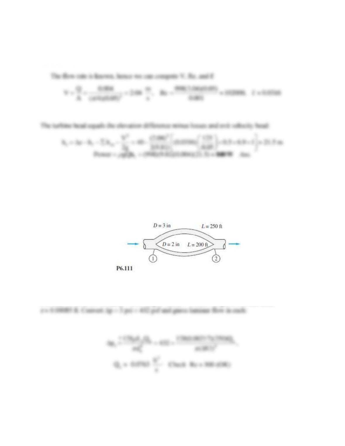
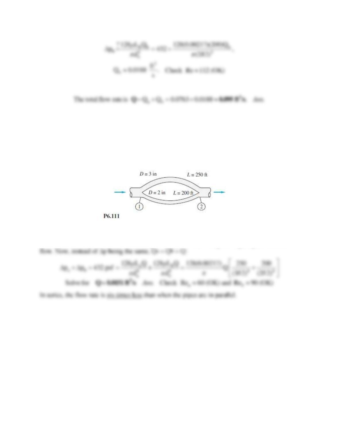
Problem 6.111
For the parallel-pipe system of Fig. P6.111, each pipe is cast iron, and the pressure drop
p1 − p2 = 3 lbf/in2. Compute the total flow rate between 1 and 2 if the fluid is SAE 10 oil at
20C.
Solution 6.111
For SAE 10 oil at 20C, take
= 1.69 slug/ft3 and
= 0.00217 slug/fts. For cast iron,
Problem 6.112
If the two pipes in Fig. P6.111 are instead laid in series with the same total pressure drop of
3 lbf/in2, what will the flow rate be? The fluid is SAE 10 oil at 20C.
Solution 6.112
For SAE 10 oil at 20C, take
= 1.69 slug/ft3 and
= 0.00217 slug/fts. Again guess laminar
Problem 6.113
The parallel galvanized-iron pipe system of Fig. P6.113 delivers water at 20C with a total flow
rate of 0.036 m3/s. If the pump is wide open and not running, with a loss coefficient K = 1.5,
determine (a) the flow rate in each pipe and (b) the overall pressure drop.