Problem 3.C1
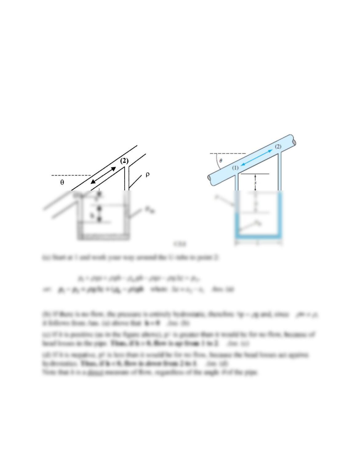
In a certain industrial process, oil of density
flows through the inclined pipe in Fig. C3.1. A
U-tube manometer with fluid density
m, measures the pressure difference between points 1 and
2, as shown. The flow is steady, so that fluids in the U-tube are stationary. (a) Find an analytic
expression for p1 − p2 in terms of system parameters. (b) Discuss the conditions on h necessary
for there to be no flow in the pipe. (c) What about flow up, from 1 to 2? (d) What about flow
down, from 2 to 1?
Solution 3.C1
Problem 3.C2
A rigid tank of volume
= 1.0 m3 is initially filled with air at 20C and po = 100 kPa. At time
t = 0, a vacuum pump is turned on and evacuates air at a constant volume flow rate Q = 80 L/min
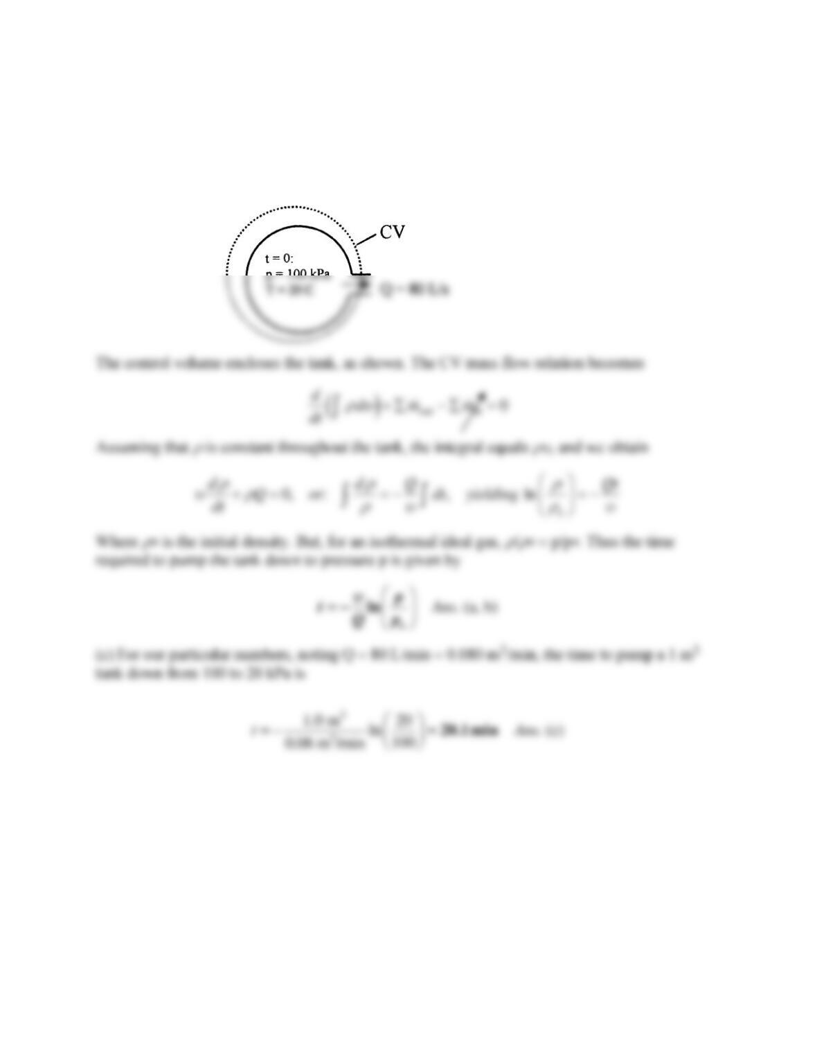
(regardless of the pressure). Assume an ideal gas and an isothermal process. (a) Set up a
differential equation for this flow. (b) Solve this equation for t as a function of (
, Q, p, po).
(c) Compute the time in minutes to pump the tank down to p = 20 kPa. Hint: Your answer should
lie between 15 and 25 minutes.
Solution 3.C2
Problem 3.C3
Suppose the same steady water jet as in Prob. 3.40 (jet velocity 8 m/s and jet diameter 10 cm)
impinges instead on a cup cavity as shown in Fig. C3.3. The water is turned 180 and exits, due
to friction, at lower velocity, Ve = 4 m/s. (Looking from the left, the exit jet is a circular annulus
of outer radius R and thickness h, flowing toward the viewer.) The cup has a radius of curvature
of 25 cm. Find (a) the thickness h of the exit jet, and (b) the force F required to hold the cupped
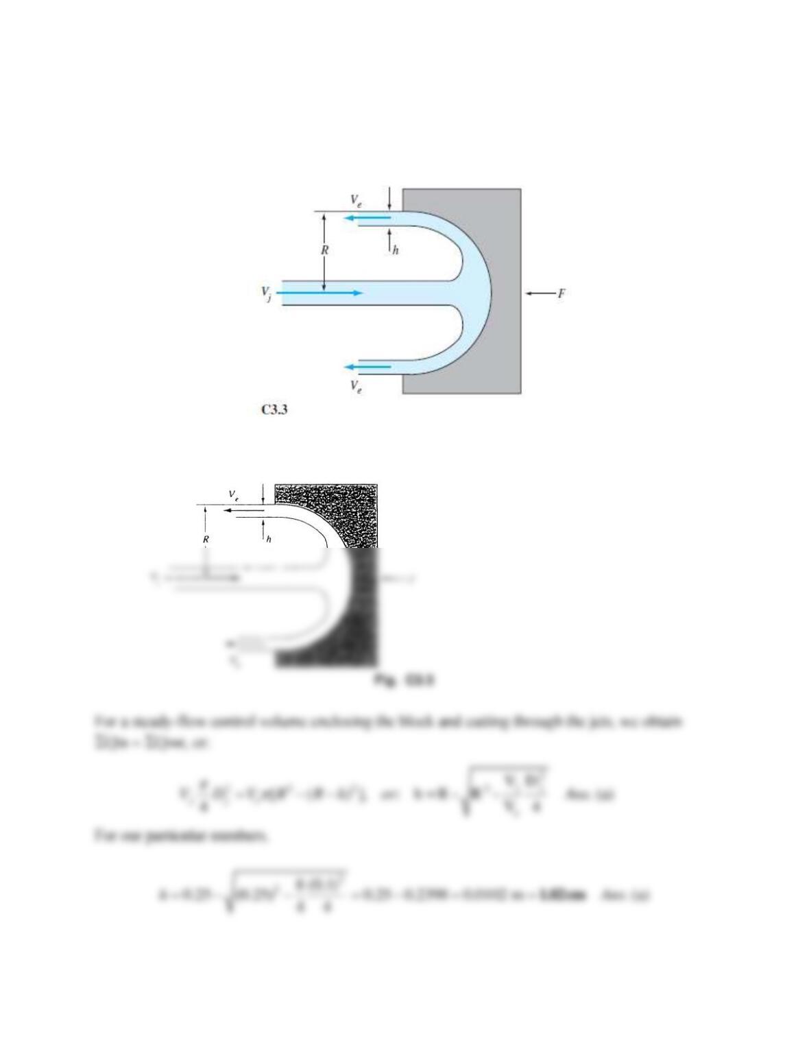
object in place. (c) Compare part (b) to Prob. 3.40, where F ≈ 500 N, and give a physical
explanation as to why F has changed.
Solution 3.C3
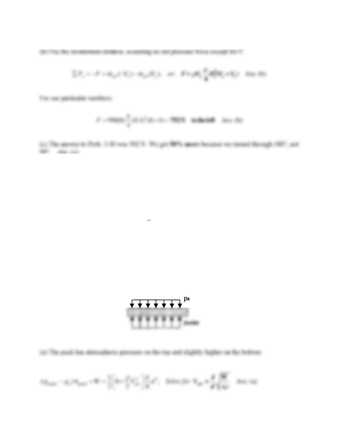
Problem 3.C4
The air flow underneath an air hockey puck is very complex, especially since the air jets from the
air hockey table impinge on the underside of the puck at various points non-symmetrically. A
reasonable approximation is that, at any given time the gage pressure on the bottom of the puck is
halfway between zero (atmospheric pressure) and the stagnation pressure of the impinging jets,
(Stagnation pressure is defined as
2
0
1
2jet
pV
=
.) (a) Find the jet velocity Vjet required to
support an air puck of weight W and diameter d. Give your answer in terms of W, d, and the
density
of the air. (b) For W = 0.05 lbf and d = 2.5 in, estimate the required jet velocity in ft/s.
Solution 3.C4
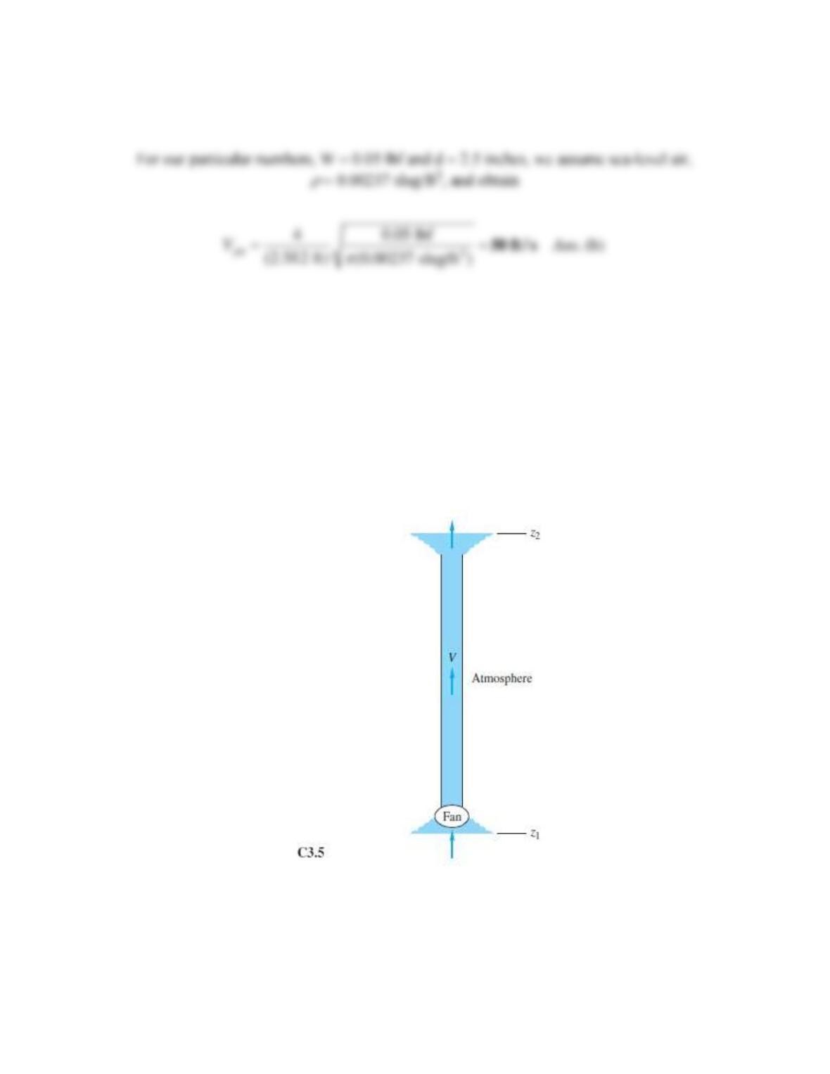
Problem 3.C5
Neglecting friction sometimes leads to odd results. You are asked to analyze and discuss the
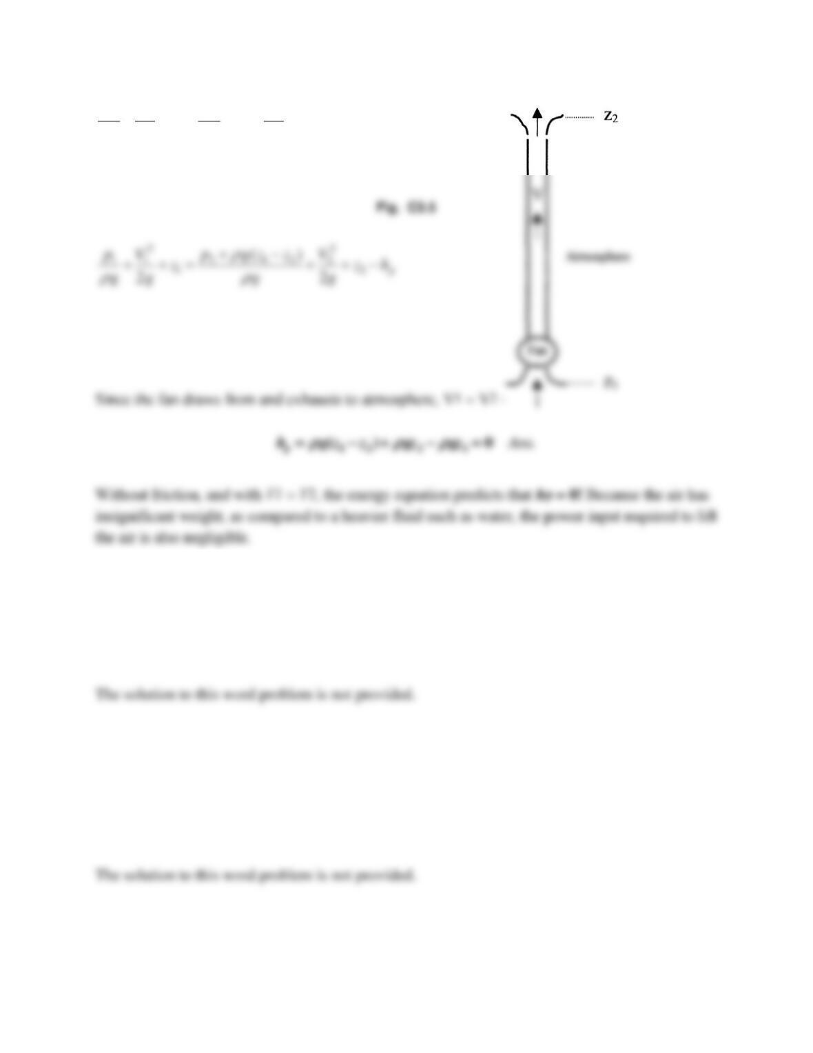
following example in Fig. C3.5. A fan blows air vertically through a duct from section 1 to
section 2, as shown. Assume constant air density
. Neglecting frictional losses, find a relation
between the required fan head hp and the flow rate and the elevation change. Then explain what
may be an unexpected result.
Solution 3.C5
Neglecting frictional losses, hf = 0, and Bernoulli becomes,
22
1 1 2 2
12
22
p
p V p V
z z h
g g g g
+ + = + + −
Problem 3.W1
Derive a control volume form of the second law of thermodynamics. Suggest some practical
uses for your relation in analyzing real fluid flows.
Solution 3.W1
Problem 3.W2
Suppose that it is desired to estimate volume flow Q in a pipe by measuring the axial velocity
u(r) at specific points. For cost reasons only three measuring points are to be used. What are the
best radii selections for these three points?
Solution 3.W2
Problem 3.W3
Consider water flowing by gravity through a short pipe connecting two reservoirs whose surface
levels differ by an amount Δz . Why does the incompressible frictionless Bernoulli equation lead
to an absurdity when the flow rate through the pipe is computed? Does the paradox have
something to do with the length of the short pipe? Does the paradox disappear if we round the
entrance and exit edges of the pipe?
Solution 3.W3
Problem 3.W4
Use the steady flow energy equation to analyze flow through a water faucet whose supply
pressure is p0 . What physical mechanism causes the flow to vary continuously from zero to
maximum as we open the faucet valve?
Solution 3.W4
Problem 3.W5
Consider a long sewer pipe, half full of water, sloping downward at angle θ . Antoine Chézy in
1768 determined that the average velocity of such an open channel flow should be
tanV C R
, where R is the pipe radius and C is a constant. How does this famous formula
relate to the steady flow energy equation applied to a length L of the channel?
Solution 3.W5
Problem 3.W6
Put a table tennis ball in a funnel, and attach the small end of the funnel to an air supply. You
probably won’t be able to blow the ball either up or down out of the funnel. Explain why.
Solution 3.W6
Problem 3.W7
How does a siphon work? Are there any limitations (such as how high or how low can you
siphon water away from a tank)? Also, how far—could you use a flexible tube to siphon water
from a tank to a point 100 ft away?
Solution 3.W7
Problem 3.1
Discuss Newton’s second law (the linear momentum relation) in these three forms:
()
system
dd
m m d
dt dt
= = =
F a F V F V
Are they all equally valid? Are they equivalent? Are some forms better for fluid mechanics as
opposed to solid mechanics?
Solution 3.1
These questions are just to get the students thinking about the basic laws of mechanics. They are
Problem 3.2
Consider the angular-momentum relation in the form
()
O
system
dd
dt
=
M r V
What does r mean in this relation? Is this relation valid in both solid and fluid mechanics? Is it
related to the linear-momentum equation (Prob. 3.1)? In what manner?
Solution 3.2
These questions are just to get the students thinking about angular momentum versus linear
Problem 3.3
For steady low-Reynolds-number (laminar) flow through a long tube (see Prob. 1.12), the axial
velocity distribution is given by u = C(R2 − r2), where R is the tube radius and r ≤ R . Integrate
u(r) to find the total volume flow Q through the tube.
Solution 3.3
The area element for this axisymmetric flow is dA = 2
r dr. From Eq. (3.7),
Problem 3.4
Water at 20ºC flows through a long elliptical duct 30 cm wide and 22 cm high. What average
velocity, in m/s, would cause the weight flow to be 500 lbf/s?
Solution 3.4
Take the specific weight of water to be γ = 62.4 lbf/ft3. Look up the area of an elliptical cross-
section of minor axis a and major axis b, A = πab. Then our duct has
Problem 3.5
Water at 20C flows through a 5-inch-diameter smooth pipe at a high Reynolds number, for
which the velocity profile is given by u
Uo(y/R)1/8, where Uo is the centerline velocity, R is
the pipe radius, and y is the distance measured from the wall toward the centerline. If the
centerline velocity is 25 ft/s, estimate the volume flow rate in gallons per minute.
Solution 3.5
The formula for average velocity in this power-law case was given in Example 3.4:
Problem 3.6
Water fills a cylindrical tank to depth h . The tank has diameter D . The water flows out at
average velocity Vo from a hole in the bottom of area Ao . Use the Reynolds transport theorem to
find an expression for the instantaneous depth change dh/dt .
Solution 3.6
From Eq. (3.20),
Problem 3.7
A spherical tank, of diameter 35 cm, is leaking air through a 5-mm-diameter hole in its side. The
air exits the hole at 360 m/s and a density of 2.5 kg/m3 . Assuming uniform mixing, (a) find a
formula for the rate of change of average density in the tank and (b) calculate a numerical value
for ( dρ/dt ) in the tank for the given data.
Solution 3.7
If the control volume surrounds the tank and cuts through the exit flow,
Problem 3.8
Three pipes steadily deliver water at 20°C to a large exit pipe in Fig. P3.8. The velocity
V2 = 5 m/s, and the exit flow rate Q4 = 120 m3/h. Find (a) V1; (b) V3; and (c) V4 if it is known
that increasing Q3 by 20 percent would increase Q4 by 10 percent.
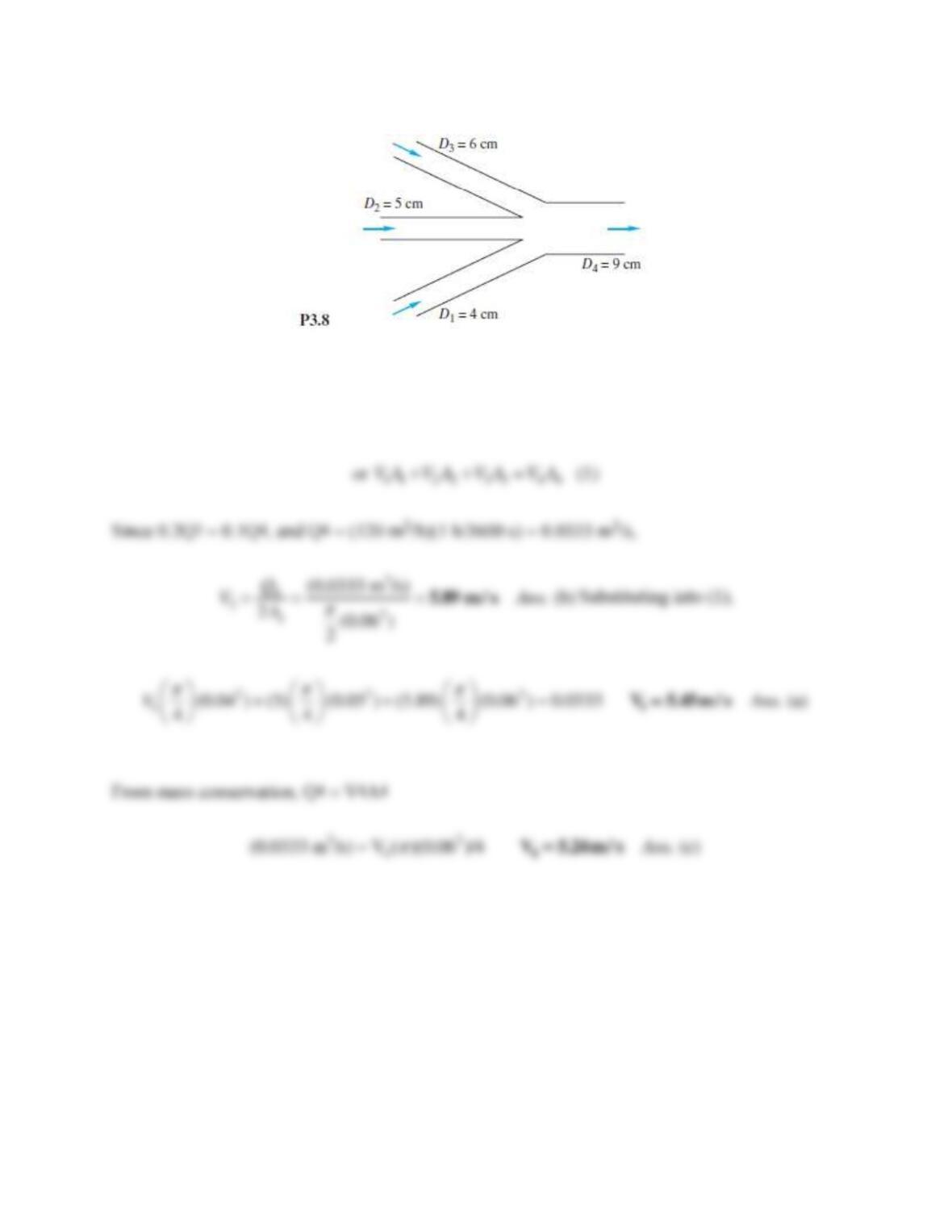
Solution 3.8
( a) For steady flow we have Q1 + Q2 + Q3 = Q4,
Problem 3.9
A laboratory test tank contains seawater of salinity S and density
. Water enters the tank at
conditions (S1,
1, A1, V1) and is assumed to mix immediately in the tank. Tank water leaves
through an outlet A2 at velocity V2. If salt is a “conservative” property (neither created nor
destroyed), use the Reynolds transport theorem to find an expression for the rate of change of
salt mass Msalt within the tank.
Solution 3.9
By definition, salinity S =
salt/
. Since salt is a “conservative” substance (not consumed or
created in this problem), the appropriate control volume relation is
Problem 3.10
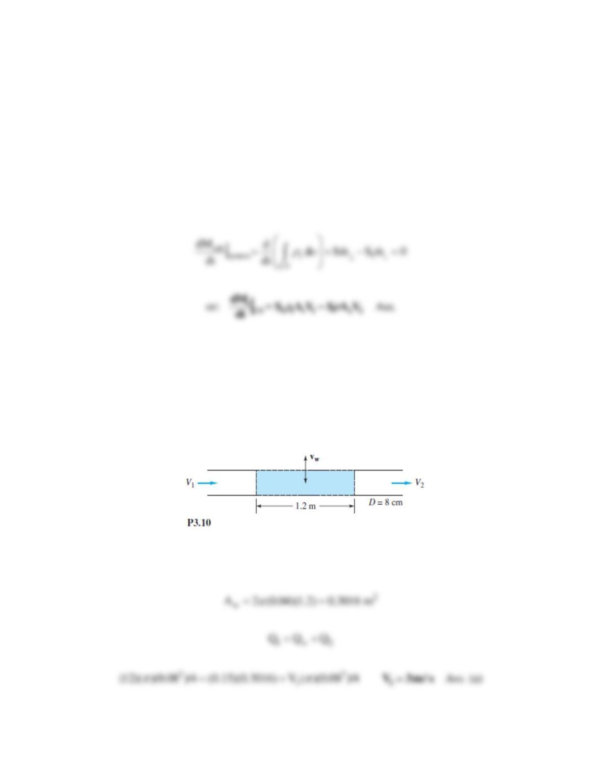
Water flowing through an 8-cm-diameter pipe enters a porous section, as in
Fig. P3.10, which allows a uniform radial velocity vw through the wall surfaces for a distance of
1.2 m. If the entrance average velocity V1 is 12 m/s, find the exit velocity V2 if (a) vw = 15 cm/s
out of the pipe walls; (b) vw = 10 cm/s into the pipe. (c) What value of vw will make V2 = 9 m/s?
Solution 3.10
(a) For a suction velocity of vw = 0.15 m/s, and a cylindrical suction surface area,
Problem 3.11
Water flows from a faucet into a sink at 3 U.S. gallons per minute. The stopper is closed, and the
sink has two rectangular overflow drains, each ⅜ in by 1¼ in. If the sink water level remains
constant, estimate the average overflow velocity, in ft/s.
Solution 3.11
This problem stresses unit conversions. One gallon = 231 in3 ÷ 1728 in3/ft3 = 0.1337 ft3. Thus
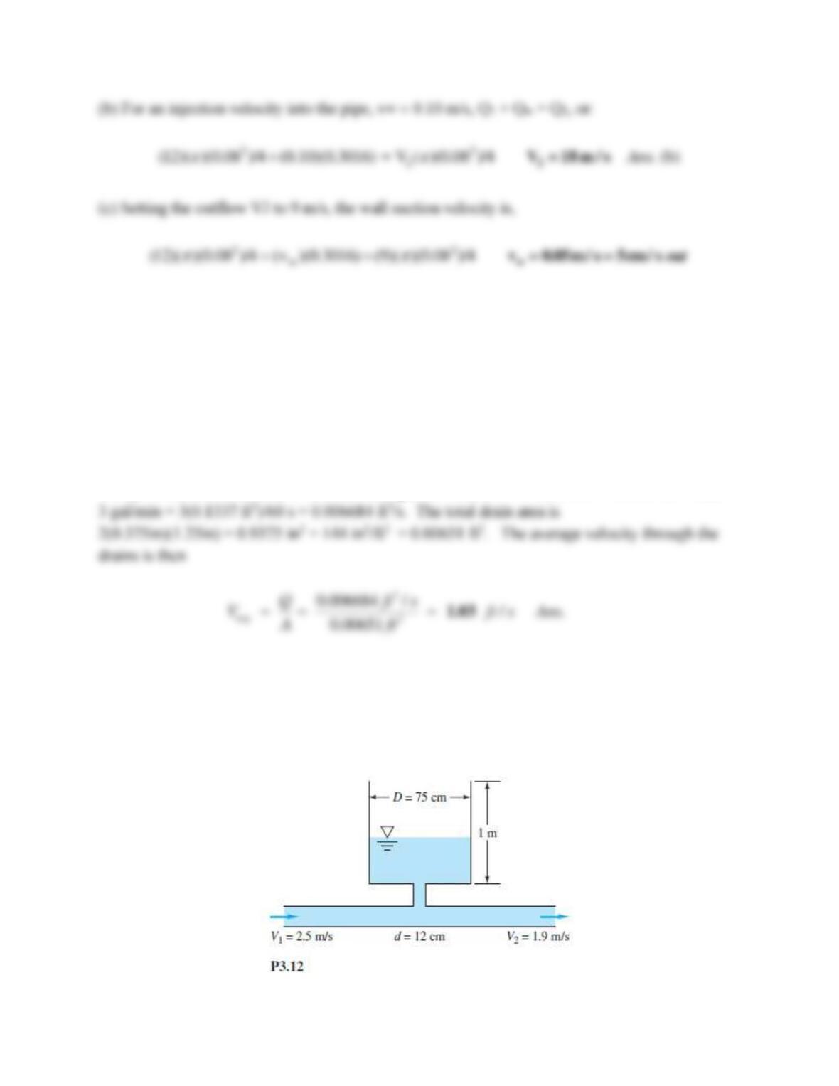
Problem 3.12
The pipe flow in Fig. P3.12 fills a cylindrical tank as shown. At time t = 0, the water depth in the
tank is 30 cm. Estimate the time required to fill the remainder of the tank.
Solution 3.12
For a control volume enclosing the tank and the portion of the pipe below the tank,
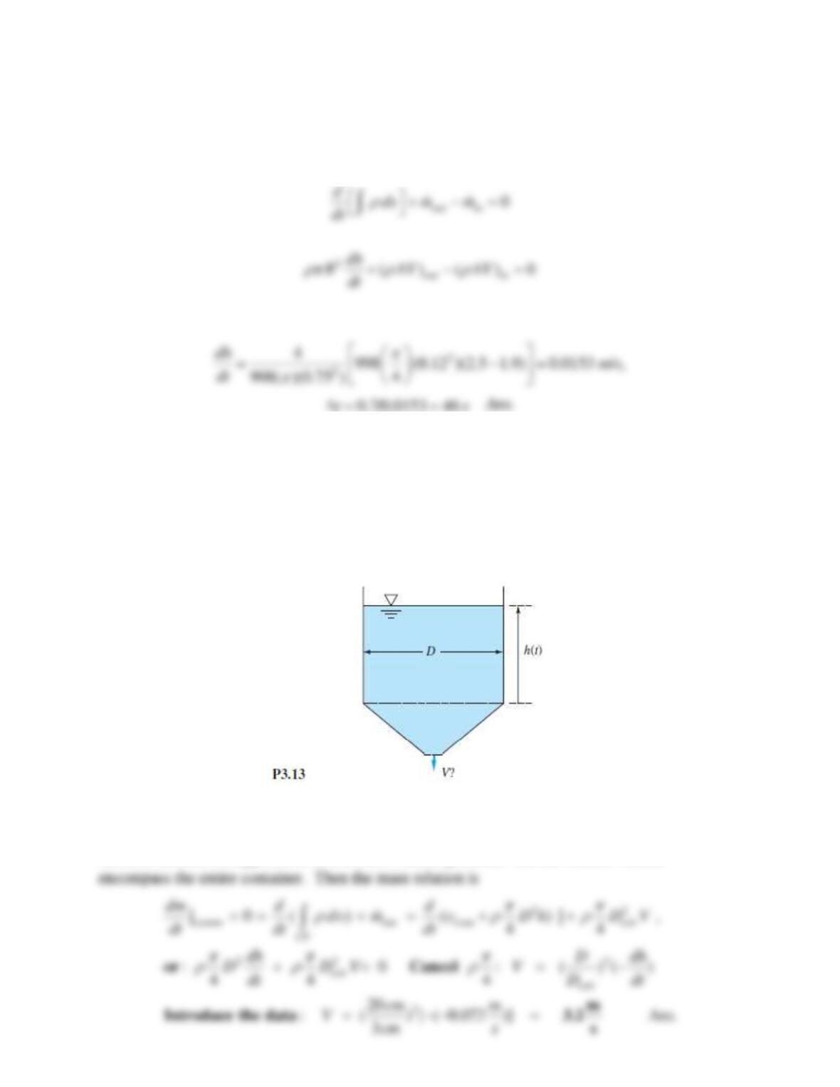
Problem 3.13
The cylindrical container in Fig. P3.13 is 20 cm in diameter and has a conical contraction at the
bottom with an exit hole 3 cm in diameter. The tank contains fresh water at standard sea-level
conditions. If the water surface is falling at the nearly steady rate dh/dt −0.072 m/s, estimate
the average velocity V from the bottom exit.
Solution 3.13
We could simply note that dh/dt is the same as the water velocity at the surface and use Q1 = Q2,
or, more instructive, approach it as a control volume problem. Let the control volume
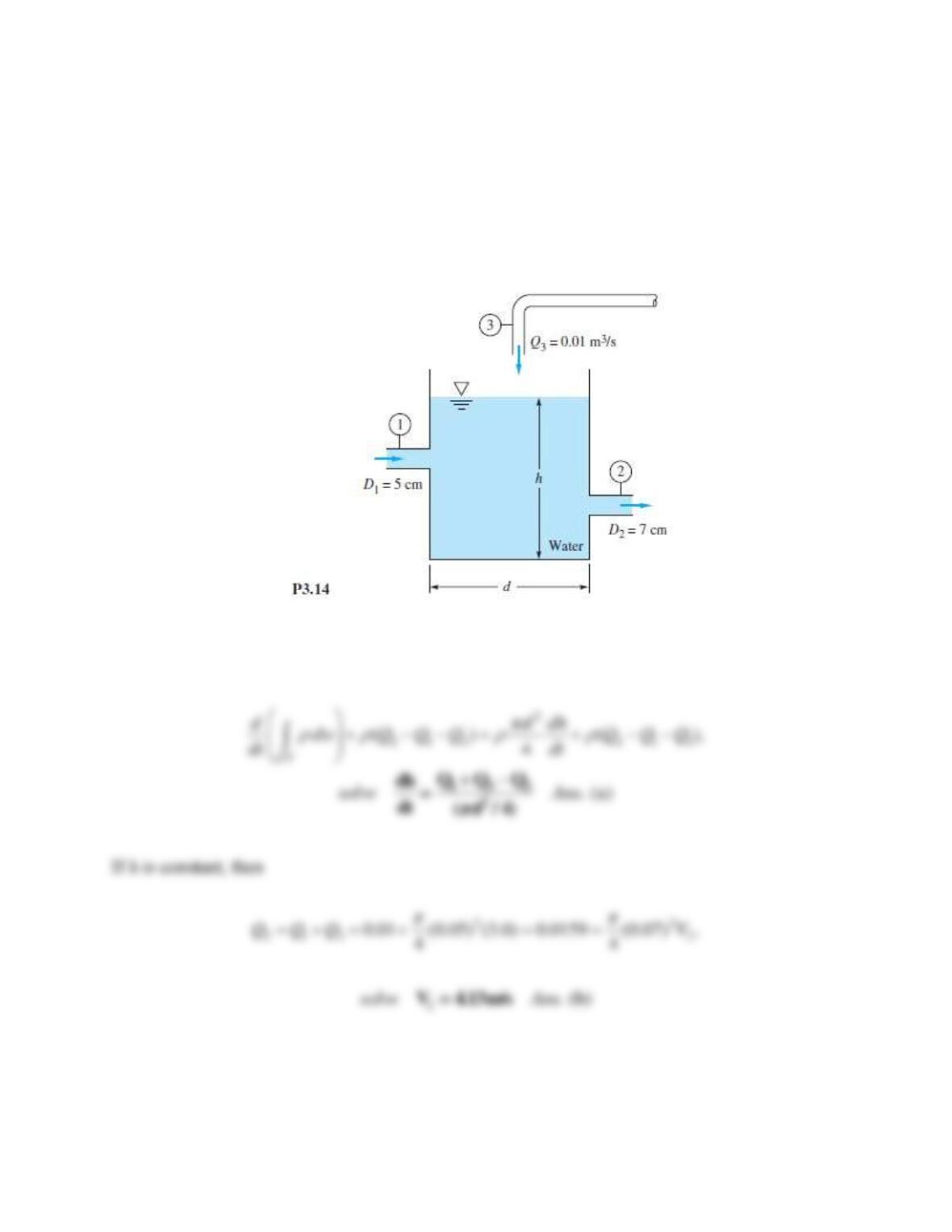
Problem 3.14
The open tank in Fig. P3.14 contains water at 20°C and is being filled through section 1. Assume
incompressible flow. First derive an analytic expression for the water-level change dh/dt in terms
of arbitrary volume flows ( Q1 , Q2 , Q3 ) and tank diameter d . Then, if the water level h is
constant, determine the exit velocity V2 for the given data V1 = 3 m/s and Q3 = 0.01 m3 /s.
Solution 3.14
For a control volume enclosing the tank,
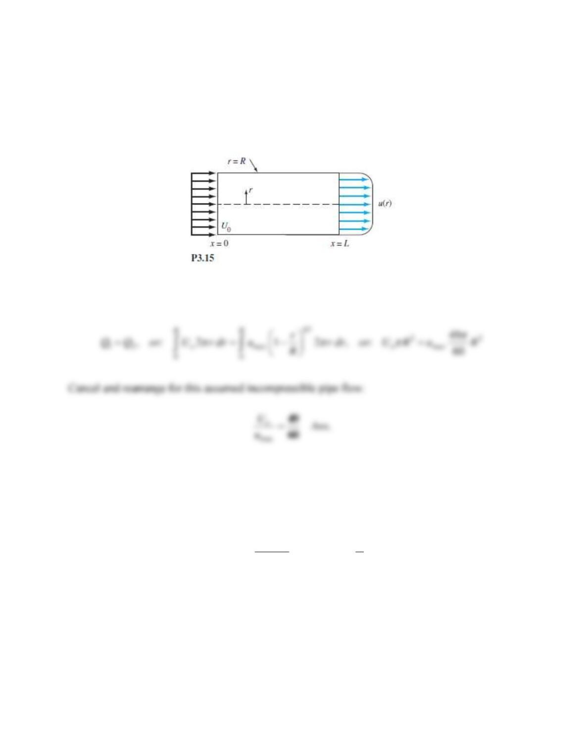
Problem 3.15
Water, assumed incompressible, flows steadily through the round pipe in Fig. P3.15. The
entrance velocity is constant, u 5 U 0 , and the exit velocity approximates turbulent flow,
u = umax (1 − r/R )1/7 . Determine the ratio U0/umax for this flow.
Solution 3.15
Inlet and outlet flow must balance:
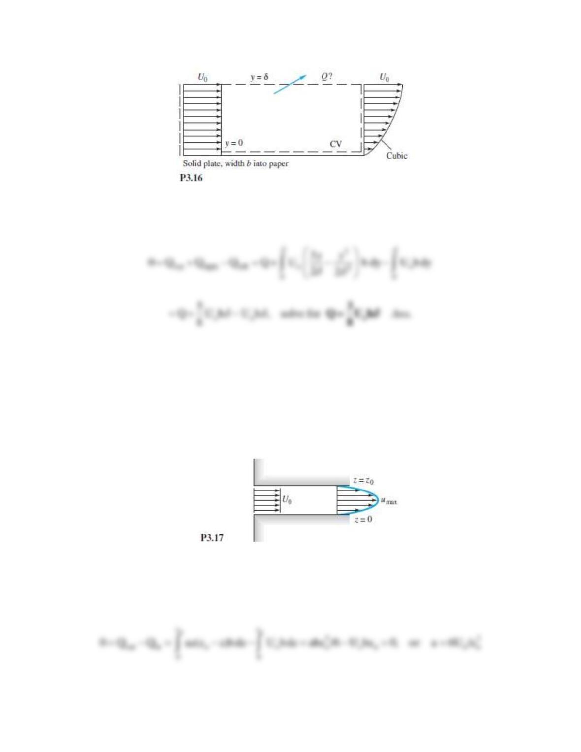
Problem 3.16
An incompressible fluid flows past an impermeable flat plate, as in Fig. P3.16, with a uniform
inlet profile u = Uo and a cubic polynomial exit profile
3
o
3where
2
y
uU
−
=
Compute the volume flow Q across the top surface of the control volume.
Solution 3.16
For the given control volume and incompressible flow, we obtain
Problem 3.17
Incompressible steady flow in the inlet between parallel plates in Fig. P3.17 is uniform,
u = Uo = 8 cm/s, while downstream the flow develops into the parabolic laminar profile
u = az(zo − z), where a is a constant. If zo = 4 cm and the fluid is SAE 30 oil at 20C, what is the
value of umax in cm/s?
Solution 3.17
Let b be the plate width into the paper. Let the control volume enclose the inlet and outlet. The
walls are solid, so no flow through the wall. For incompressible flow,
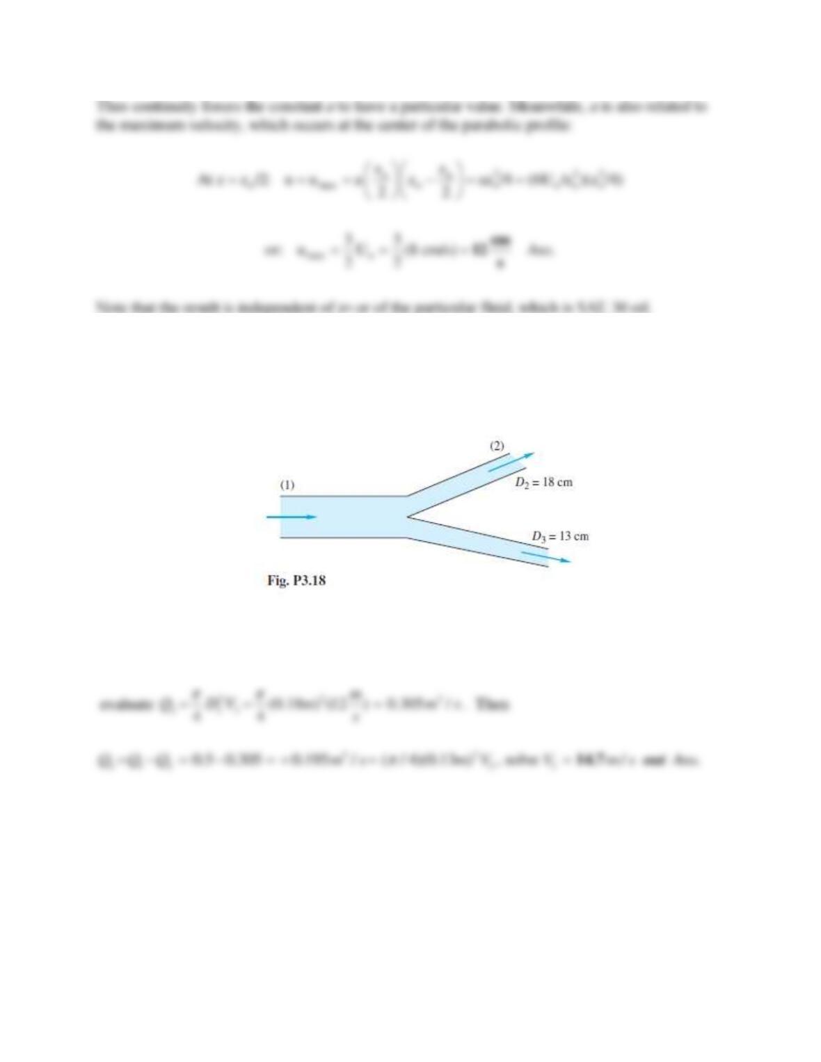
Problem 3.18
Gasoline enters Section 1 in Fig. P3.18 at 0.5 m3/s. It leaves Section 2 at an average velocity of
12 m/s. What is the average velocity at Section 3? Is it in or out?
Solution 3.18
Given Q1 = 0.5 m3/s,
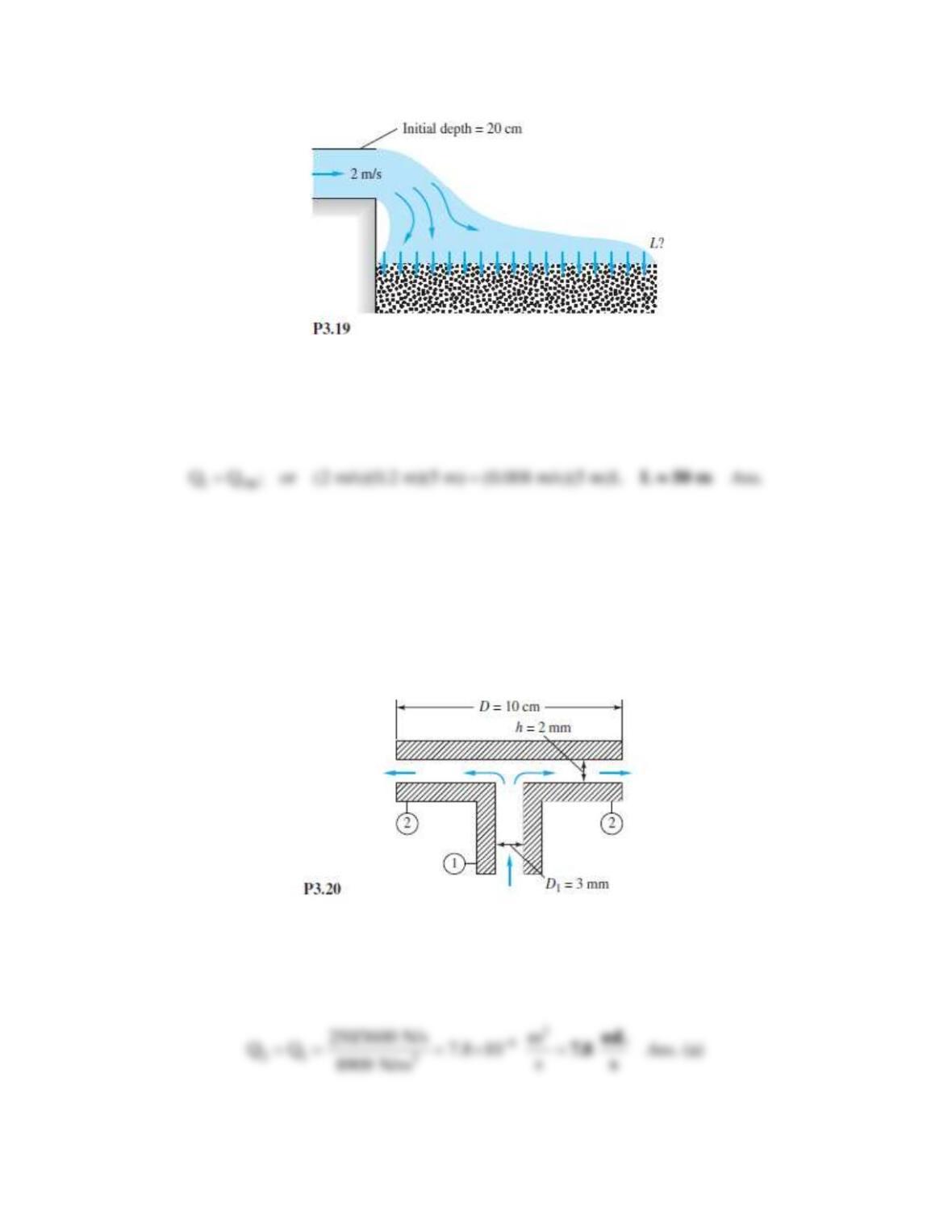
Problem 3.19
Water from a storm drain flows over an outfall onto a porous bed which absorbs the water at a
uniform vertical velocity of 8 mm/s, as shown in Fig. P3.19. The system is 5 m deep into the
paper. Find the length L of bed which will completely absorb the storm water.
Solution 3.19
For the bed to completely absorb the water, the flow rate over the outfall must equal that into the
porous bed,
Problem 3.20
Oil (SG = 0.89) enters at section 1 in Fig. P3.20 at a weight flow of 250 N/h to lubricate a thrust
bearing. The steady oil flow exits radially through the narrow clearance between thrust plates.
Compute (a) the outlet volume flow in mL/s and (b) the average outlet velocity in cm/s.
Solution 3.20
The specific weight of the oil is (0.91)(9790) = 8909 N/m3. Then
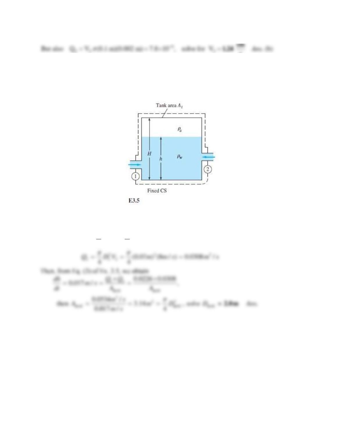
Problem 3.21
For the two-port tank of Fig. E3.5, assume D1 = 4 cm, V1 = 18 m/s, D2 = 7 cm, and V2 = 8 m/s. If
the tank surface is rising at 17 mm/s, estimate the tank diameter.
Solution 3.21
We need the flow rates and can then use the results of Ex. 3.5:
2 2 3
1 1 1
(0.04 ) (18 / ) 0.0226 /
44
Q D V m m s m s
= = =
Problem 3.22
The converging-diverging nozzle shown in Fig. P3.22 expands and accelerates dry air to
supersonic speeds at the exit, where p2 = 8 kPa and T2 = 240 K. At the throat,
p1 = 284 kPa, T1 = 665 K, and V1 = 517 m/s. For steady compressible flow of an ideal gas,
estimate (a) the mass flow in kg/h, (b) the velocity V2, and (c) the Mach number Ma2.