Unlock document.
This document is partially blurred.
Unlock all pages and 1 million more documents.
Get Access
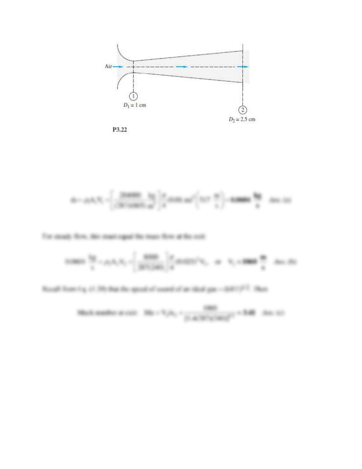
Solution 3.22
The mass flow is given by the throat conditions:
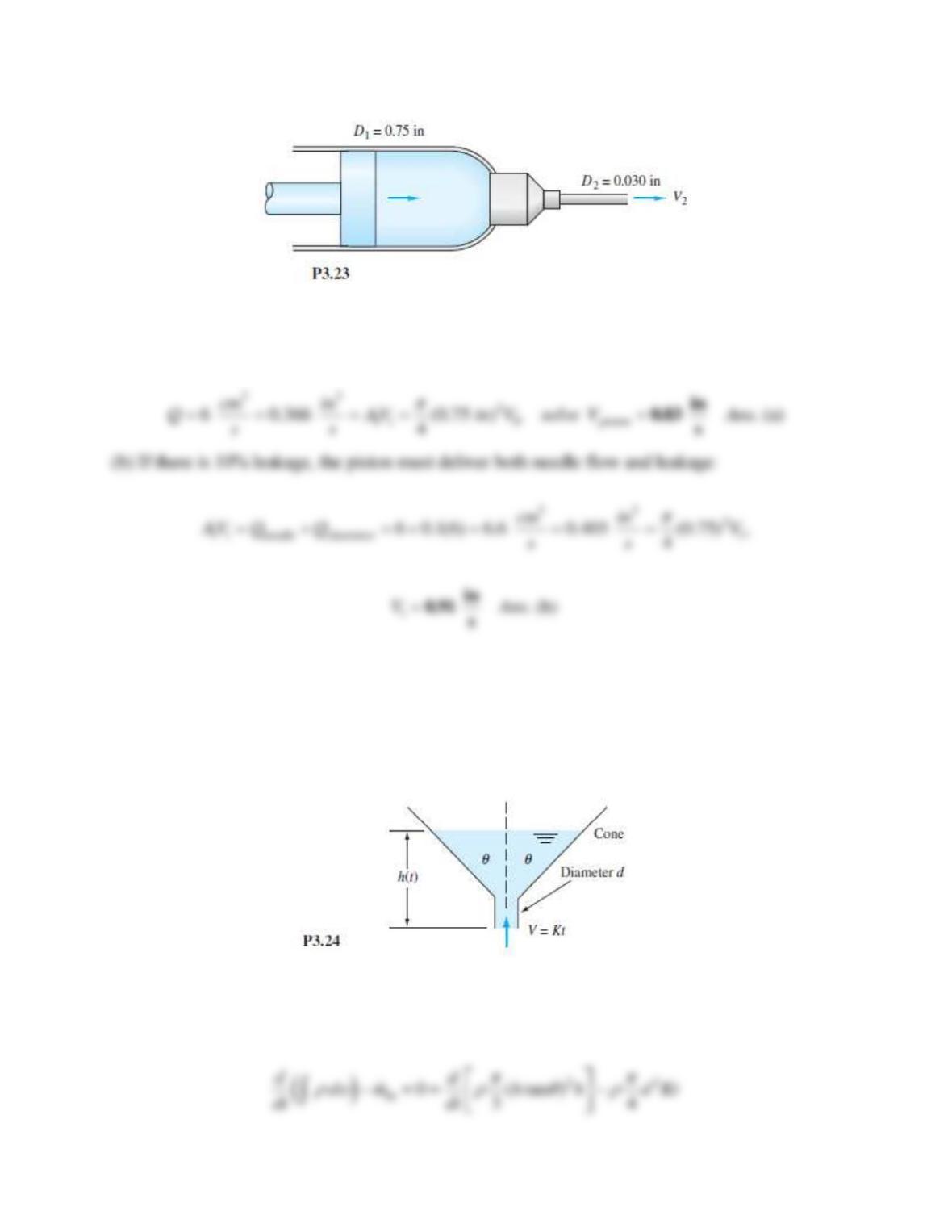
Problem 3.23
The hypodermic needle in Fig. P3.23 contains a liquid serum (SG = 1.05). If the serum is to be
injected steadily at 6 cm3 /s, how fast in in/s should the plunger be advanced (a) if leakage in the
plunger clearance is neglected and (b) if leakage is 10 percent of the needle flow?
Solution 3.23
(a) For incompressible flow, the volume flow is the same at piston and exit:
Problem 3.24*
Water enters the bottom of the cone in Fig. P3.24 at a uniformly increasing average velocity
V = Kt . If d is very small, derive an analytic formula for the water surface rise h(t) for the
condition h = 0 at t = 0. Assume incompressible flow.
Solution 3.24
For a control volume around the cone, the mass relation becomes
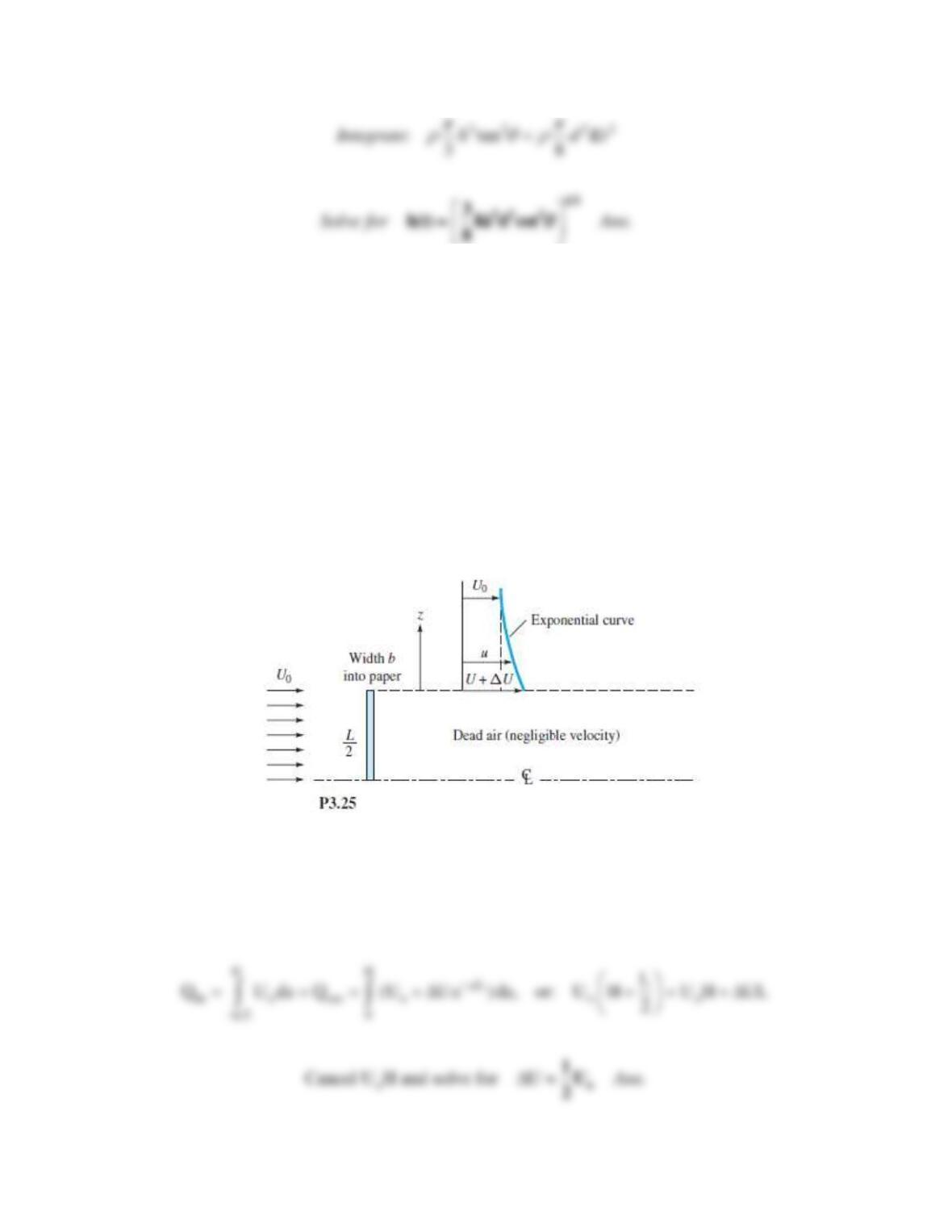
Problem 3.25
As will be discussed in Chaps. 7 and 8, the flow of a stream Uo past a blunt flat plate creates a
broad low-velocity wake behind the plate. A simple model is given in Fig. P3.25, with only half
of the flow shown due to symmetry. The velocity profile behind the plate is idealized as “dead air”
(near-zero velocity) behind the plate, plus a higher velocity, decaying vertically above the wake
according to the variation u
Uo + Ue−z/L, where L is the plate height and z = 0 is the top of the wake.
Find U as a function of stream speed Uo.
Solution 3.25
For a control volume enclosing the upper half of the plate and the section where the exponential
profile applies, extending upward to a large distance H such that exp(–H/L) 0, we must have
inlet and outlet volume flows the same:
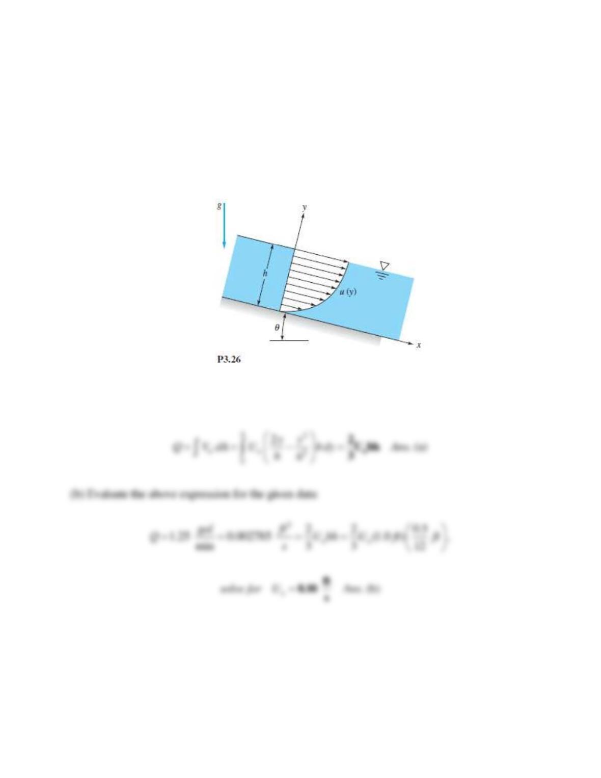
Problem 3.26
A thin layer of liquid, draining from an inclined plane, as in the Fig. P3.26, will have a laminar
velocity profile u = Uo(2y/h − y2/h2), where Uo is the surface velocity. If the plane has width b into
the paper, (a) deter-mine the volume rate of flow of the film. (b) Suppose that h = 0.5 in and
the flow rate per foot of channel width is 1.25 gal/min. Estimate Uo in ft/s.
Solution 3.26
(a) The total volume flow is computed by integration over the flow area:
Problem 3.27
Consider a highly pressurized air tank at conditions (po,
o, To) and volume
o. In Chap. 9 we
will learn that, if the tank is allowed to exhaust to the atmosphere through a well-designed
converging nozzle of exit area A, the outgoing mass flow rate will be
This rate persists as long as po is at least twice as large as the atmospheric pressure. Assuming
constant To and an ideal gas, (a) derive a formula for the change of density
o(t) within the tank.
(b) Analyze the time t required for the density to decrease by 25 percent.
Solution 3.27
First convert the formula to reflect tank density instead of pressure:
Problem 3.28
Air, assumed to be a perfect gas from Table A.4, flows through a long, 2-cm-diameter insulated
tube. At section 1, the pressure is 1.1 MPa and the temperature is 345 K. At section 2, 67
meters further downstream, the density is 1.34 kg/m3, the temperature 298 K, and the Mach
number is 0.90. For one-dimensional flow, calculate (a) the mass flow; (b) p2; (c) V2; and (d) the
change in entropy between 1 and 2. (e) How do you explain the entropy change?
airfor685.0where, =
o
o
RT
Ap
m

Solution 3.28
For air, k = 1.40 and R = 287 m2/s2-K, hence cp = kR/(k-1) = 1005 m2/s2-K.
(a, c) We have enough information at section 2 to calculate the velocity, hence the mass flow:
Problem 3.29
In elementary compressible-flow theory (Chap. 9), compressed air will exhaust from a small hole
in a tank at the mass flow rate
,mC
where
is the air density in the tank and C is a constant.
If
o is the initial density in a tank of volume v, derive a formula for the density change
(t) after
the hole is opened. Apply your formula to the following case: a spherical tank of diameter 50 cm,
with initial pressure 300 kPa and temperature 100°C, and a hole whose initial exhaust rate is
0.01 kg/s. Find the time required for the tank density to drop by 50 percent.
Solution 3.29
For a control volume enclosing the tank and the exit jet, we obtain
Problem 3.30
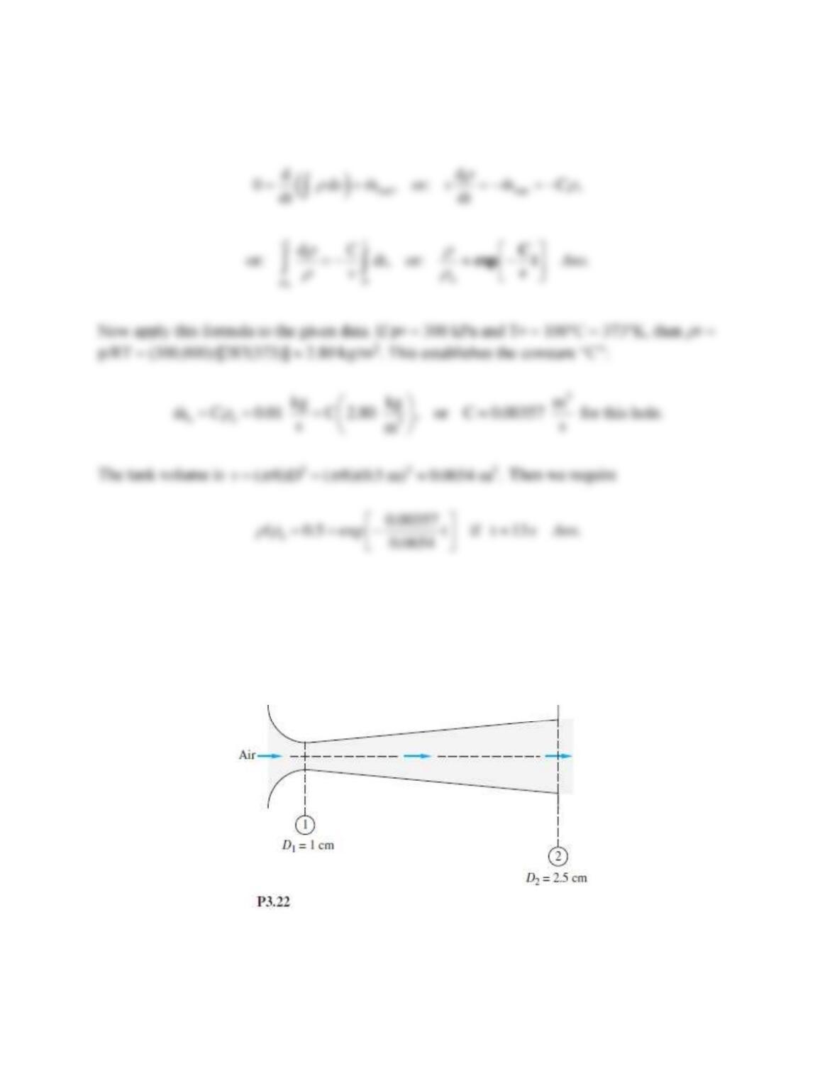
For the nozzle of Fig. P3.22, consider the following data for air, k = 1.4. At the throat,
p1 = 1000 kPa, V1 = 491 m/s, and T1 = 600 K. At the exit, p2 = 28.14 kPa. Assuming isentropic
steady flow, compute (a) the Mach number Ma1; (b) T2 ; (c) the mass flow; and (d) V2.
Solution 3.30
The throat information gives us Mach number and mass flow:
1
1 1 1
1
491
( ) 1.4(287)(600) 491 , hence .( )
491
V
m
a a kRT Ma Ans a
sa
= = = = = =
1.00
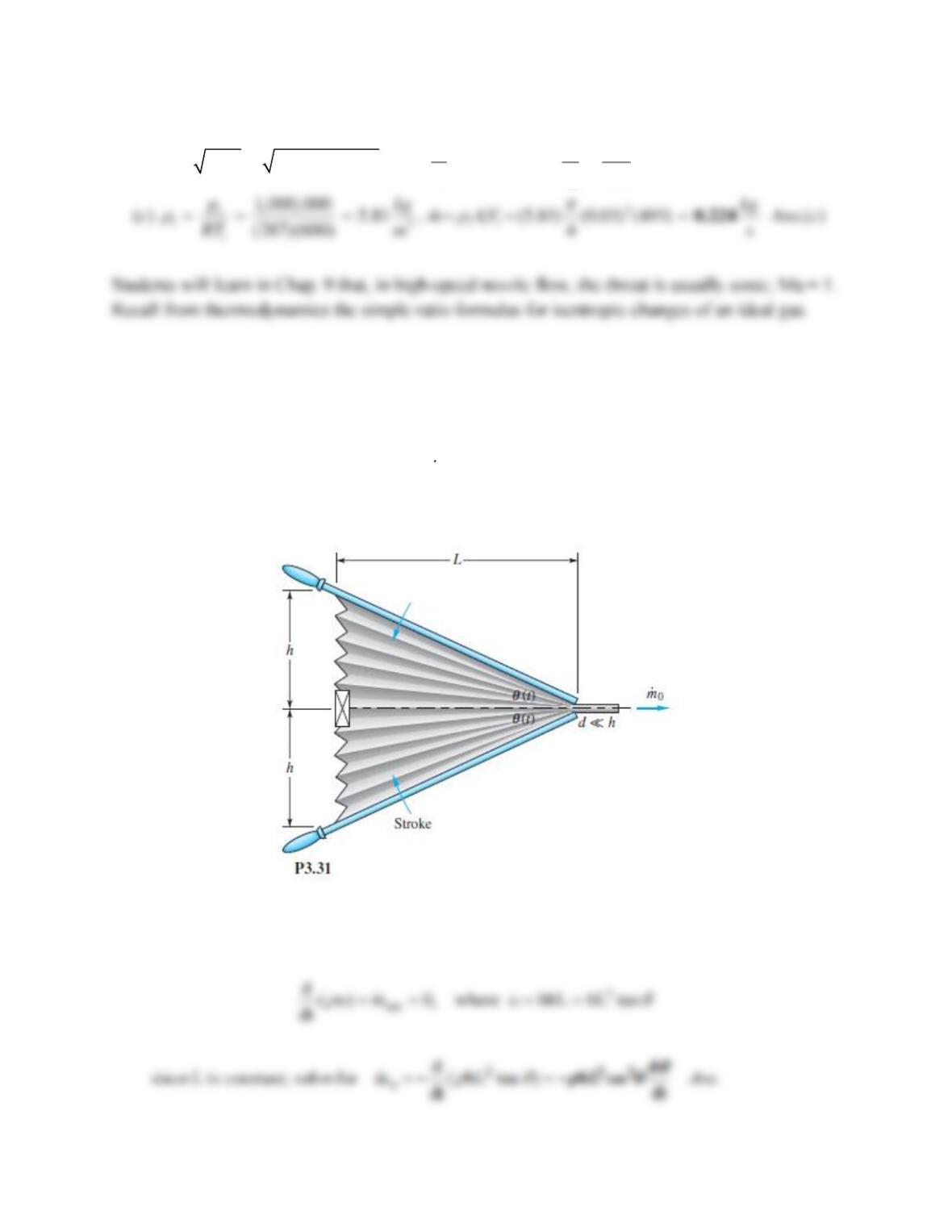
Problem 3.31
A bellows may be modeled as a deforming wedge-shaped volume as in Fig. P3.31. The check
valve on the left (pleated) end is closed during the stroke. If b is the bellows width into the paper,
derive an expression for outlet mass flow
o
m
as a function of stroke
(t).
Solution 3.31
For a control volume enclosing the bellows and the outlet flow, we obtain
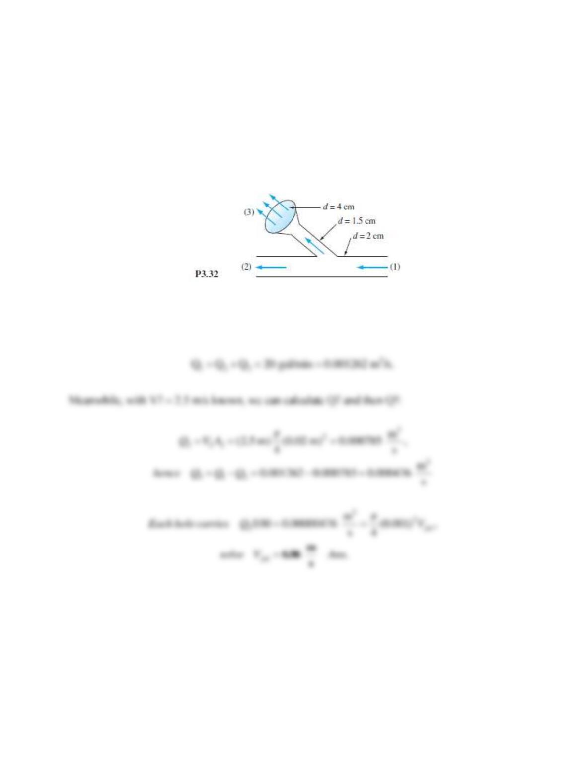
Problem 3.32
Water at 20°C flows through the piping junction in Fig. P3.32, entering section 1 at 20 gal/min.
The average velocity at section 2 is 2.5 m/s. A portion of the flow is diverted through the
showerhead, which contains 100 holes of 1-mm diameter. Assuming uniform shower flow,
estimate the exit velocity from the showerhead jets.
Solution 3.32
A control volume around sections (1, 2, 3) yields
Problem 3.33
In some wind tunnels the test section is perforated to suck out fluid and provide a thin viscous
boundary layer. The test section wall in Fig. P3.33 contains 1200 holes of 5-mm diameter each
per square meter of wall area. The suction velocity through each hole is Vr = 8 m/s, and the test-
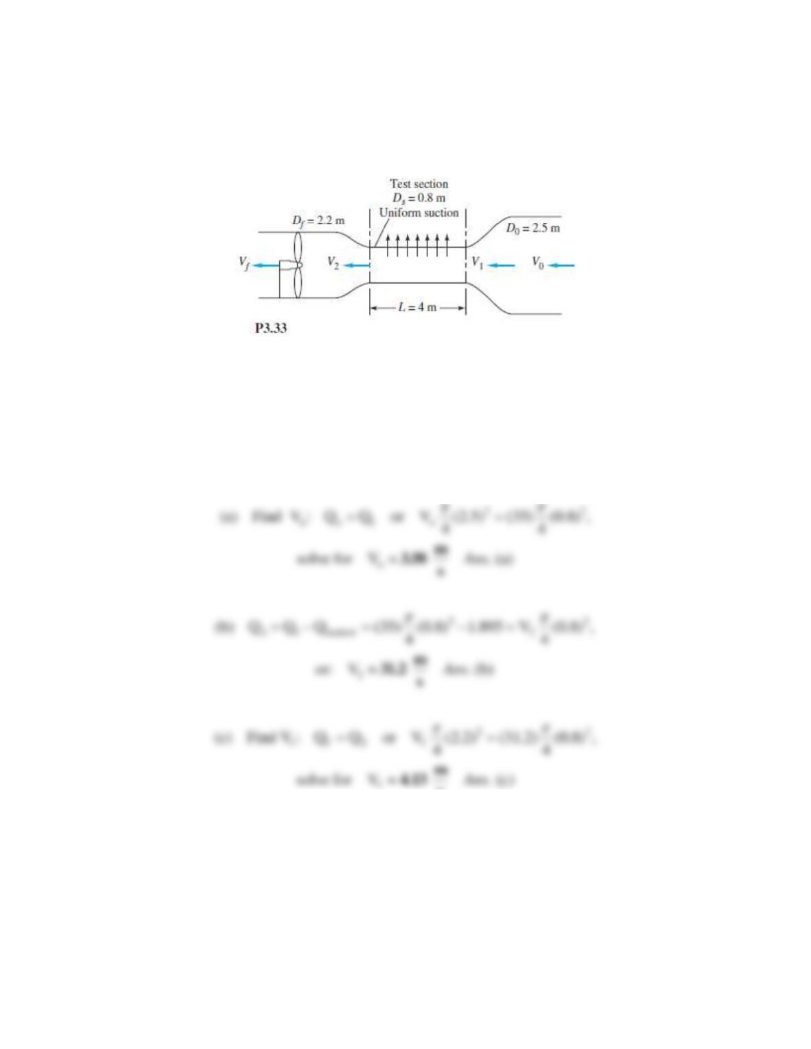
section entrance velocity is V1 = 35 m/s. Assuming incompressible steady flow of air at 20°C,
compute (a) Vo, (b) V2, and (c) Vf, in m/s.
Solution 3.33
The test section wall area is (
)(0.8 m)(4 m) = 10.053 m2, hence the total number of holes is
(1200)(10.053) = 12064 holes. The total suction flow leaving is
23
suction hole
Q NQ (12064)( /4)(0.005 m) (8 m/s) 1.895 m /s
= =
Problem 3.34
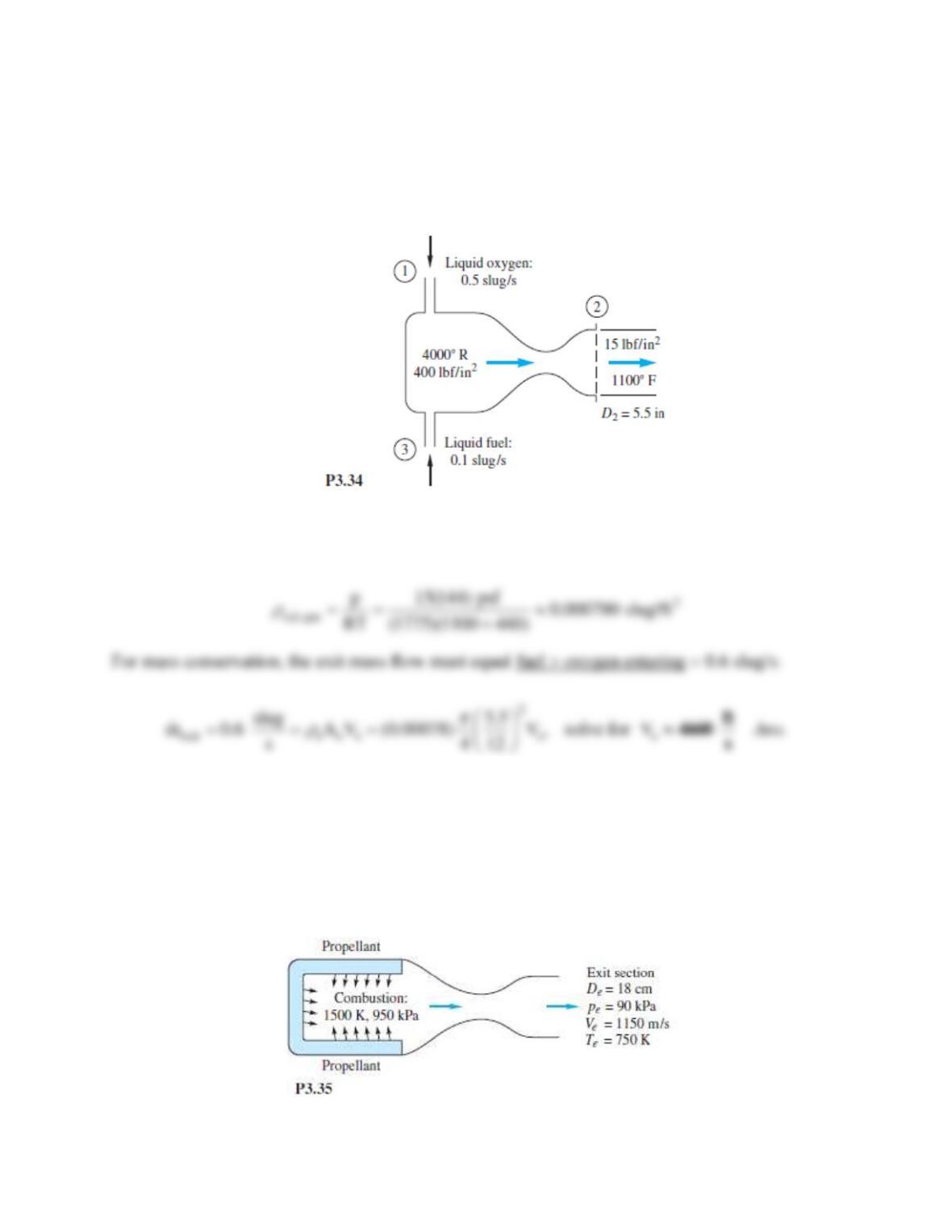
A rocket motor is operating steadily, as shown in Fig. P3.34. The products of combustion
flowing out the exhaust nozzle approximate a perfect gas with a molecular weight of 28. For the
given conditions calculate V2 in ft/s.
Solution 3.34
Exit gas: Molecular weight = 28, thus Rgas = 49700/28 = 1775 ft2/(s2°R). Then,
Problem 3.35
In contrast to the liquid rocket in Fig. P3.34, the solid-propellant rocket in Fig. P3.35 is self-
contained and has no entrance ducts. Using a control-volume analysis for the conditions shown
in Fig. P3.35, compute the rate of mass loss of the propellant, assuming that the exit gas has a
molecular weight of 28.
Solution 3.35
With M = 28, R = 8313/28 =297 m2/(s2K), hence the exit gas density is
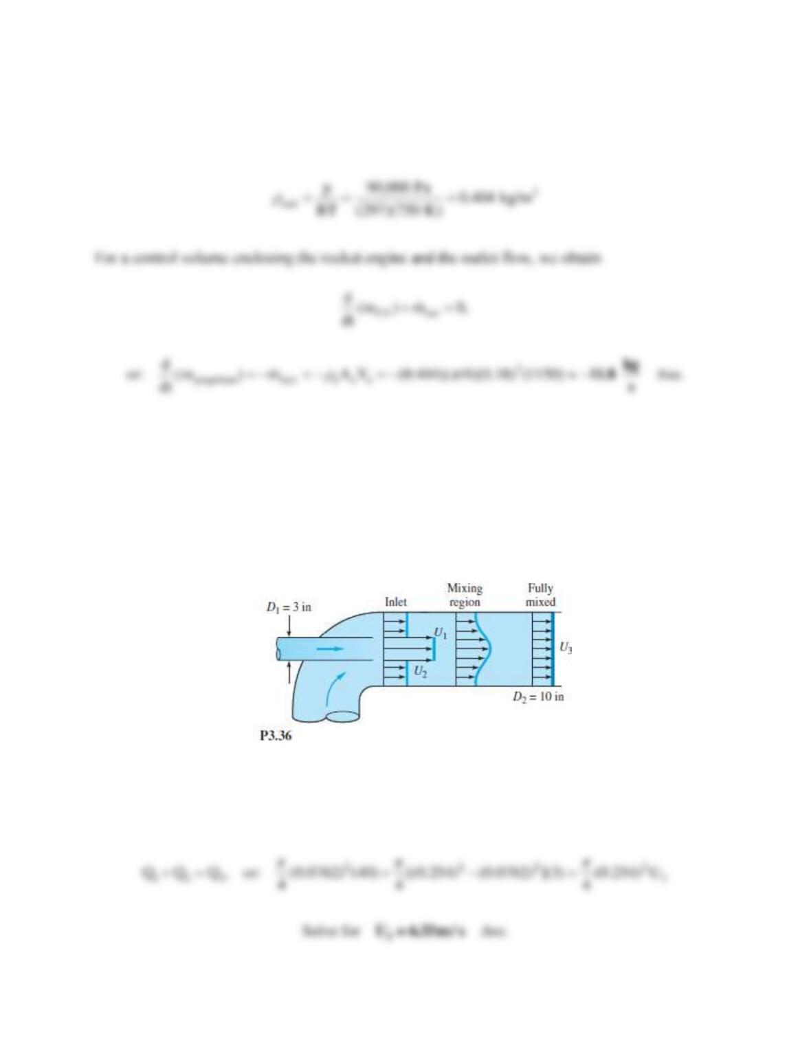
Problem 3.36
The jet pump in Fig. P3.36 injects water at U1 = 40 m/s through a 3-in pipe and entrains a
secondary flow of water U2 = 3 m/s in the annular region around the small pipe. The two flows
become fully mixed down-stream, where U3 is approximately constant. For steady incompressible
flow, compute U3 in m/s.
Solution 3.36
First modify the units: D1 = 3 in = 0.0762 m, D2 = 10 in = 0.254 m. For incompressible flow, the
volume flows at inlet and exit must match:
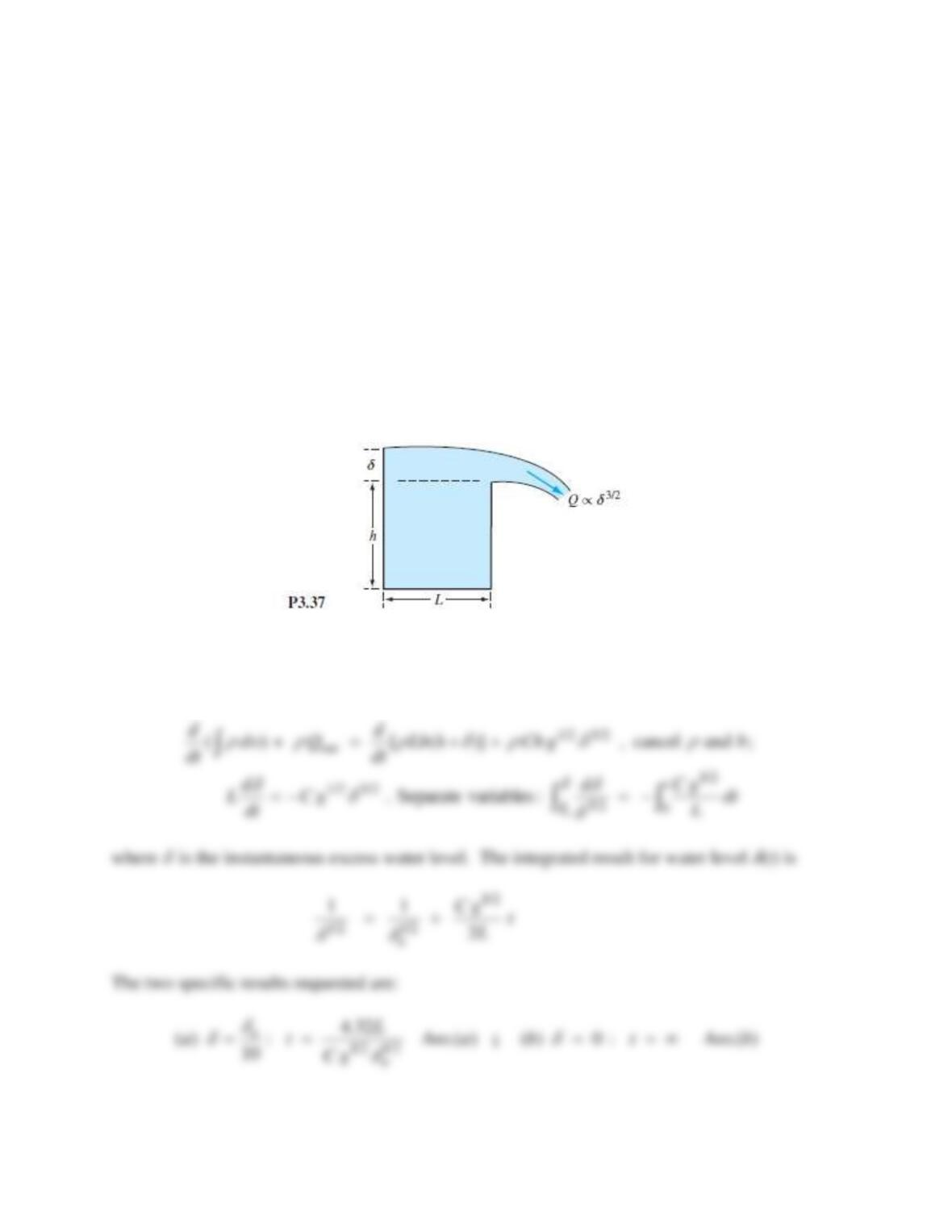
Problem 3.37
If the rectangular tank full of water, in Fig. P3.37, has its right-hand wall lowered by an amount
, as shown, water will flow out as it would over a weir or dam. In Prob. P1.14 we deduced that
the outflow Q would be given by
1/ 2 3/ 2
=Q C b g
where b is the tank width into the paper, g is the acceleration of gravity, and C is a dimensionless
constant. Assume that the water surface is horizontal, not slightly curved as in the figure. Let
the initial excess water level be
o. Derive a formula for the time required to reduce the excess
water level to (a)
o/10; and (b) to zero.
Solution 3.37
The control volume encloses the tank and cuts through the outlet flow. From Eq. (3.20),
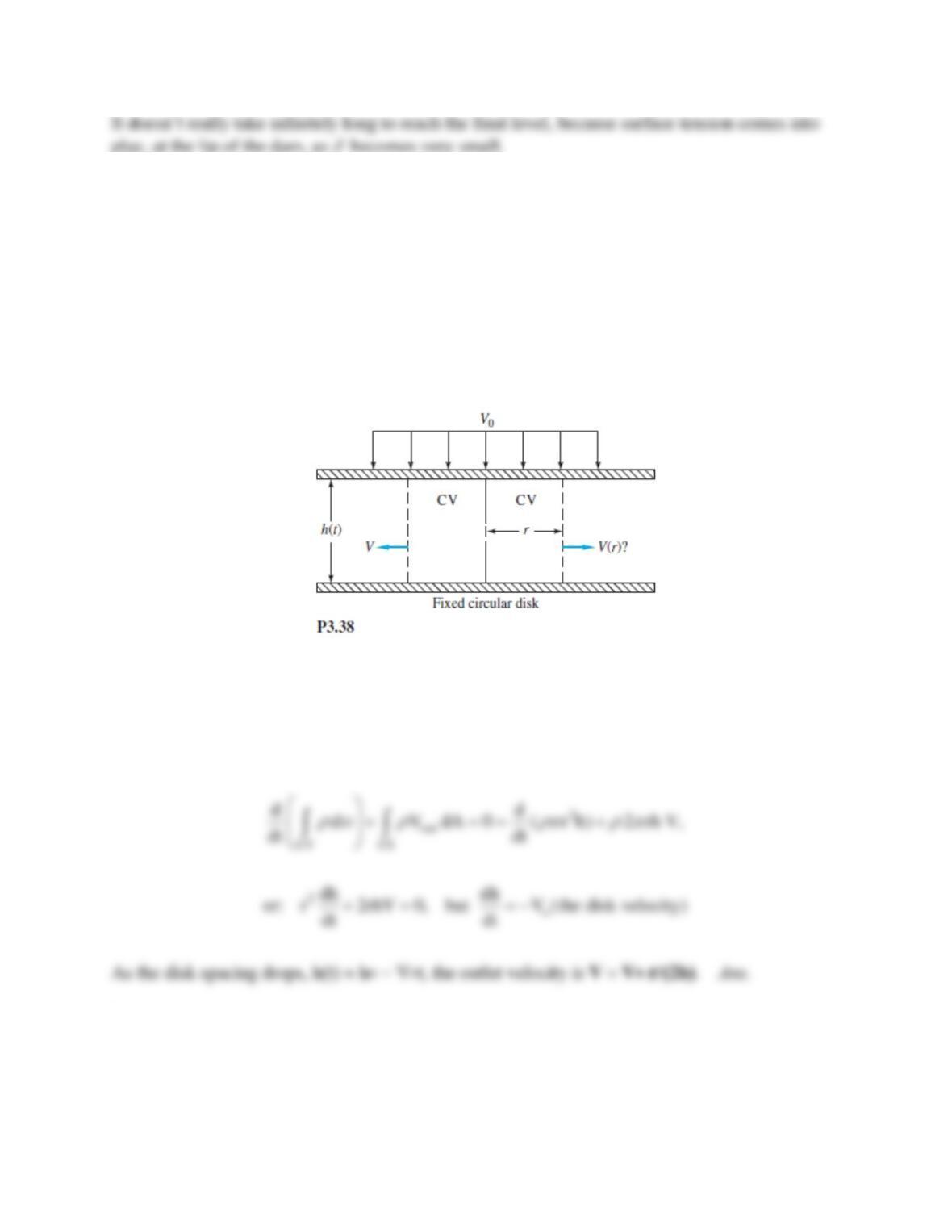
Problem 3.38
An incompressible fluid in Fig. P3.38 is being squeezed outward between two large circular
disks by the uniform downward motion V0 of the upper disk. Assuming one-dimensional radial
outflow, use the control volume shown to derive an expression for V (r).
Solution 3.38
Let the CV enclose the disks and have an upper surface moving down at speed Vo. There is no
inflow. Thus
Problem 3.39
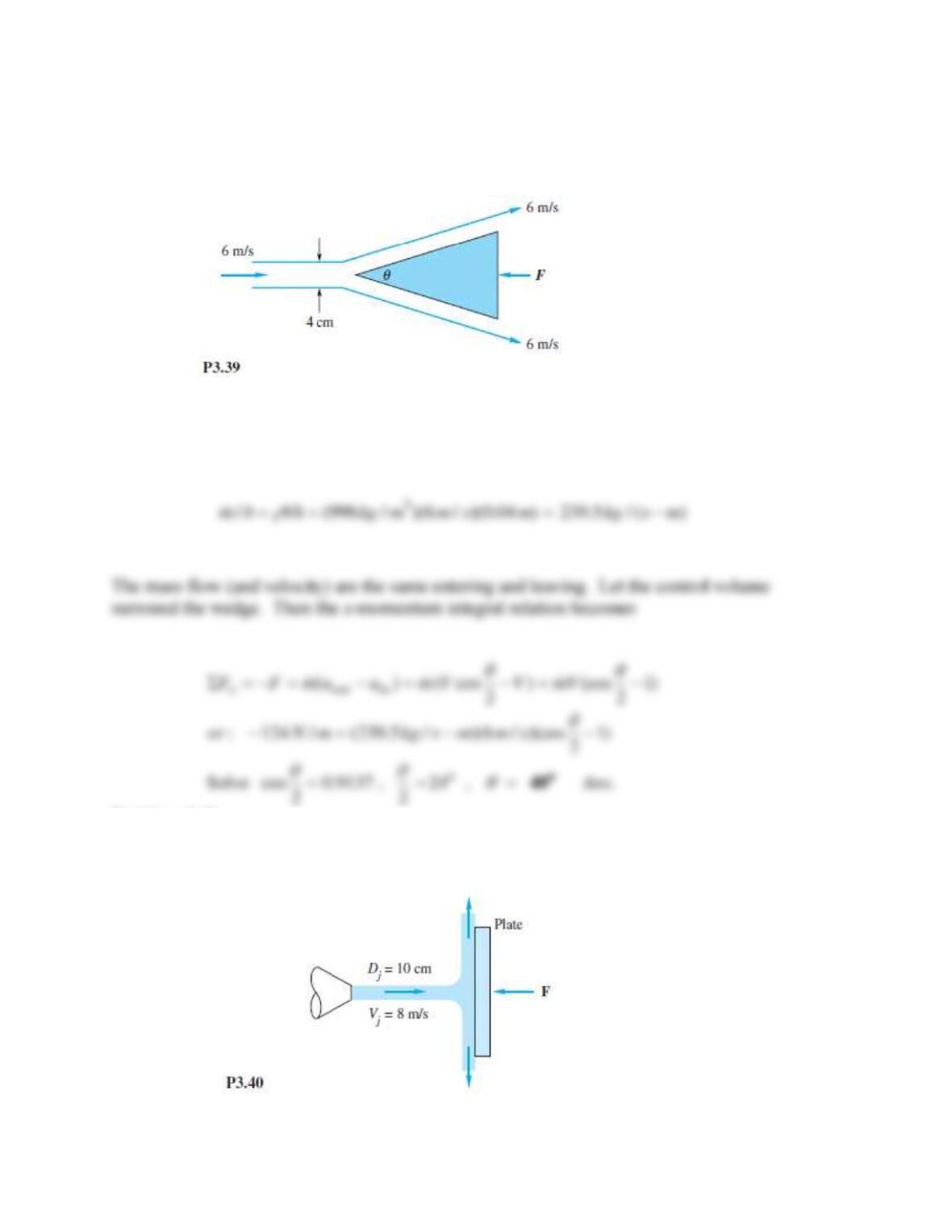
A wedge splits a sheet of 20C water, as shown in Fig. P3.39. Both wedge and sheet are very
long into the paper. If the force required to hold the wedge stationary is F = 126 N per meter of
depth into the paper, what is the angle
of the wedge?
Solution 3.39
For water take
= 998 kg/m3. First compute the mass flow per unit depth:
Problem 3.40
The water jet in Fig. P3.40 strikes normal to a fixed plate. Neglect gravity and friction, and
compute the force F in newtons required to hold the plate fixed.
Solution 3.40
For a CV enclosing the plate and the impinging jet, we obtain:
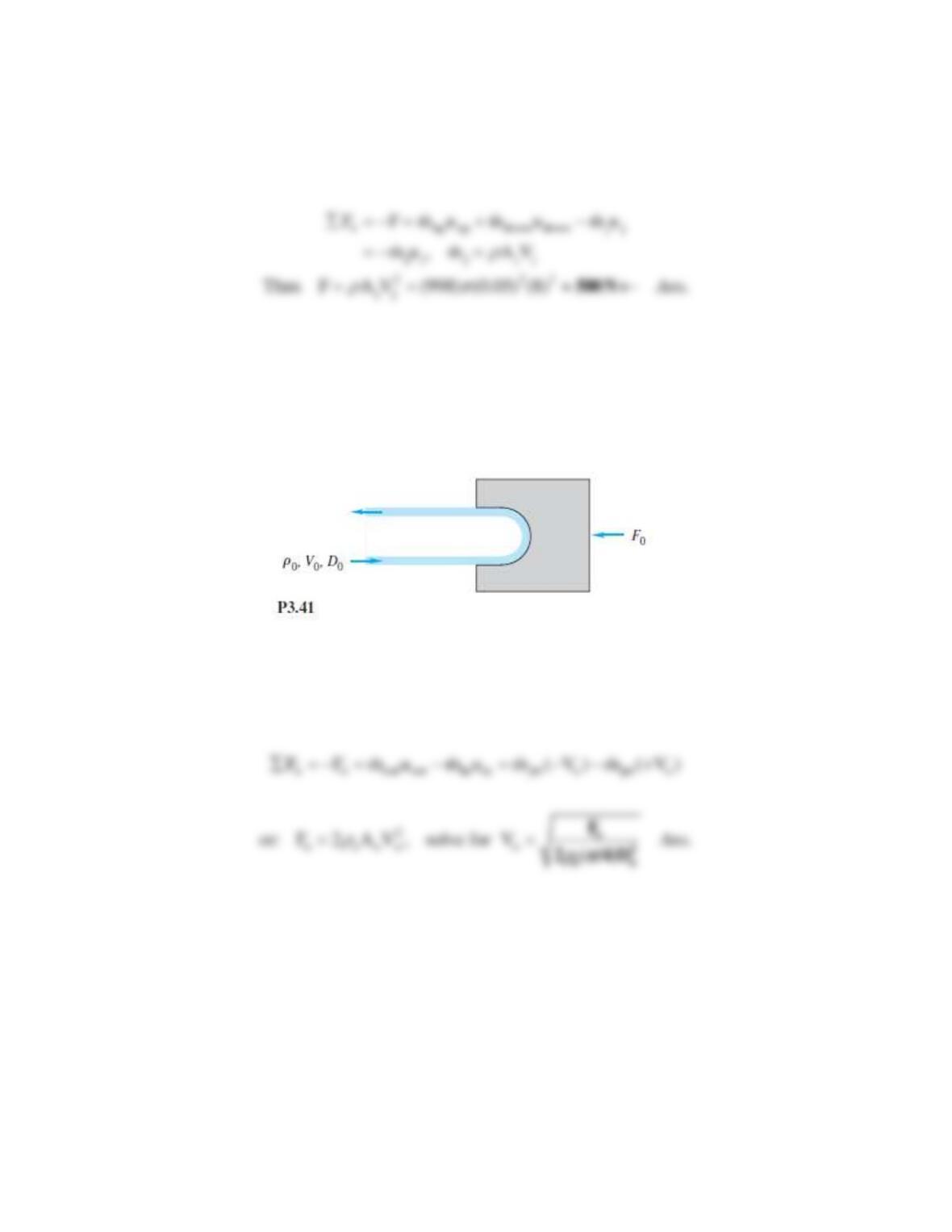
Problem 3.41
In Fig. P3.41 the vane turns the water jet completely around. Find the maximum jet velocity Vo
for a force Fo.
Solution 3.41
For a CV enclosing the vane and the inlet and outlet jets,
Problem 3.42
A liquid of density
flows through the sudden contraction in Fig. P3.42 and exits to the
atmosphere. Assume uniform conditions (p1, V1, D1) at section 1 and (p2, V2, D2) at section 2.
Find an expression for the force F exerted by the fluid on the contraction.
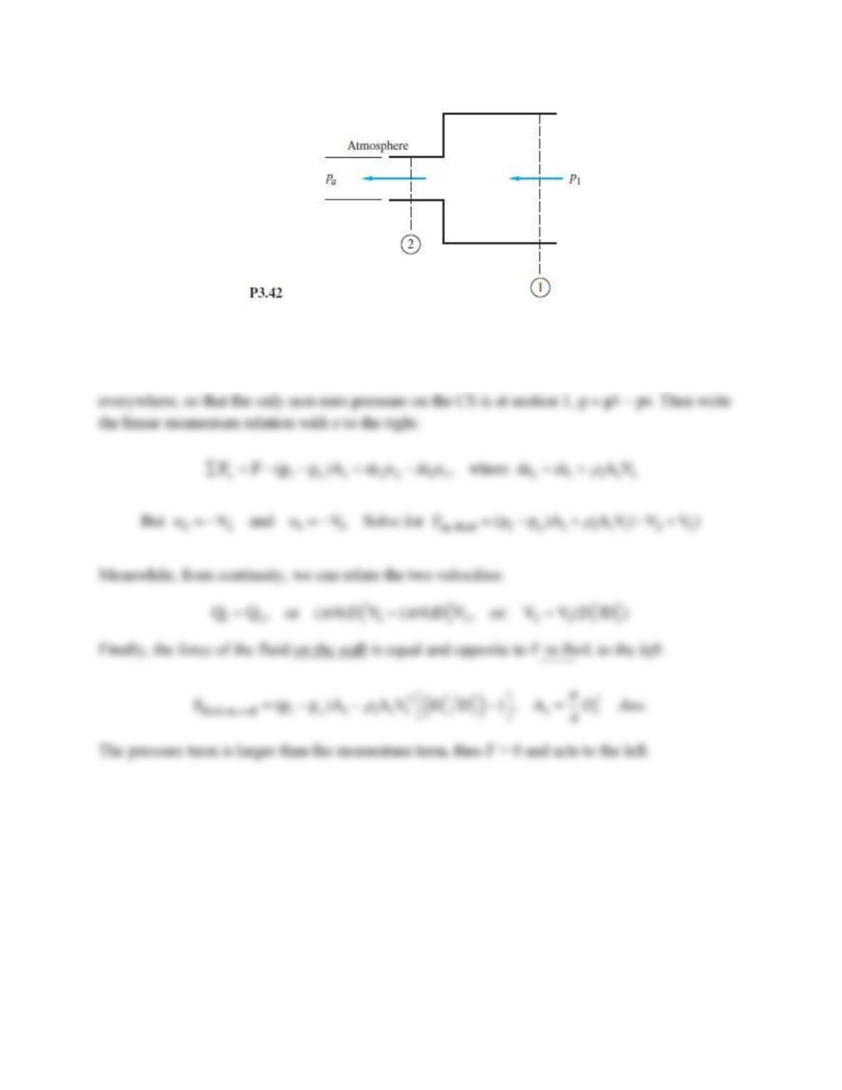
Solution 3.42
Since the flow exits directly to the atmosphere, the exit pressure equals atmospheric: p2 = pa. Let
the CV enclose sections 1 and 2, as shown. Use our trick (page 129 of the text) of subtracting pa
Problem 3.43
Water at 20°C flows through a 5-cm-diameter pipe which has a 180° vertical bend, as in
Fig. P3.43. The total length of pipe between flanges 1 and 2 is 75 cm. When the weight flow rate
is 230 N/s, p1 = 165 kPa, and p2 = 134 kPa. Neglecting pipe weight, determine the total force
which the flanges must withstand for this flow.
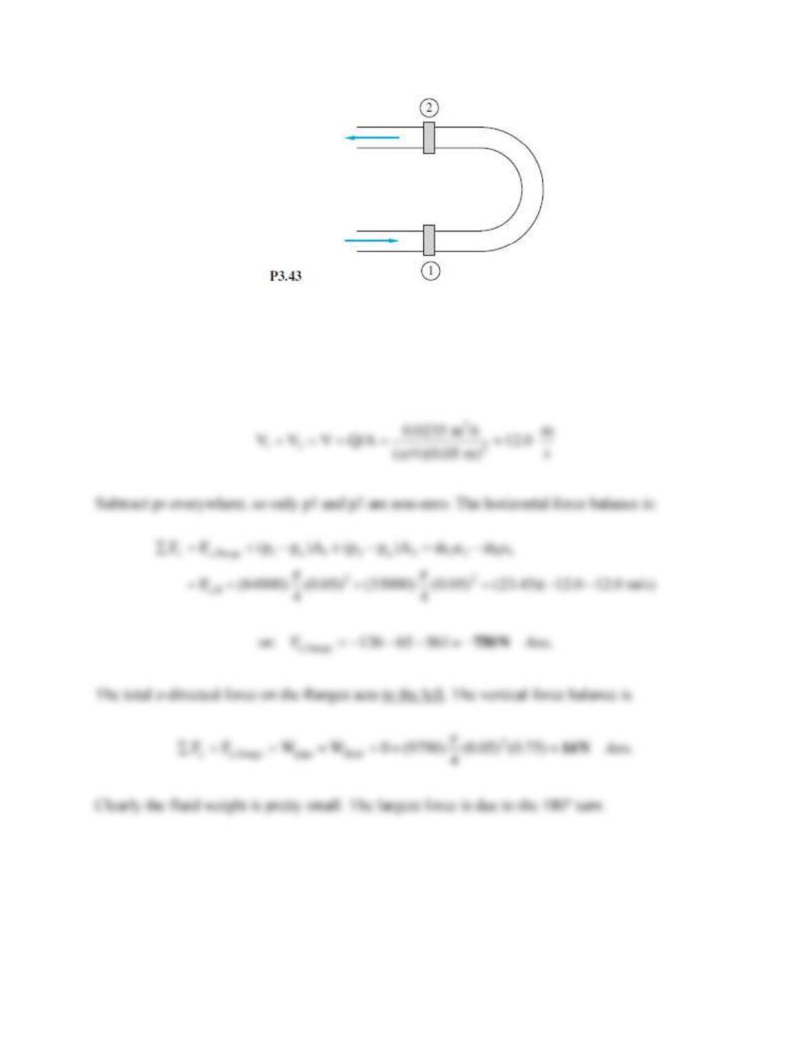
Solution 3.43
Let the CV cut through the flanges and surround the pipe bend. The mass flow rate is (230
N/s)/(9.81 m/s2) = 23.45 kg/s. The volume flow rate is Q = 230/9790 = 0.0235 m3/s. Then the pipe
inlet and exit velocities are the same magnitude:
Problem 3.44*
When a uniform stream flows past an immersed thick cylinder, a broad low-velocity wake is
created downstream, idealized as a V shape in Fig. P3.44. Pressures p1 and p2 are approximately
equal. If the flow is two-dimensional and incompressible, with width b into the paper, derive a
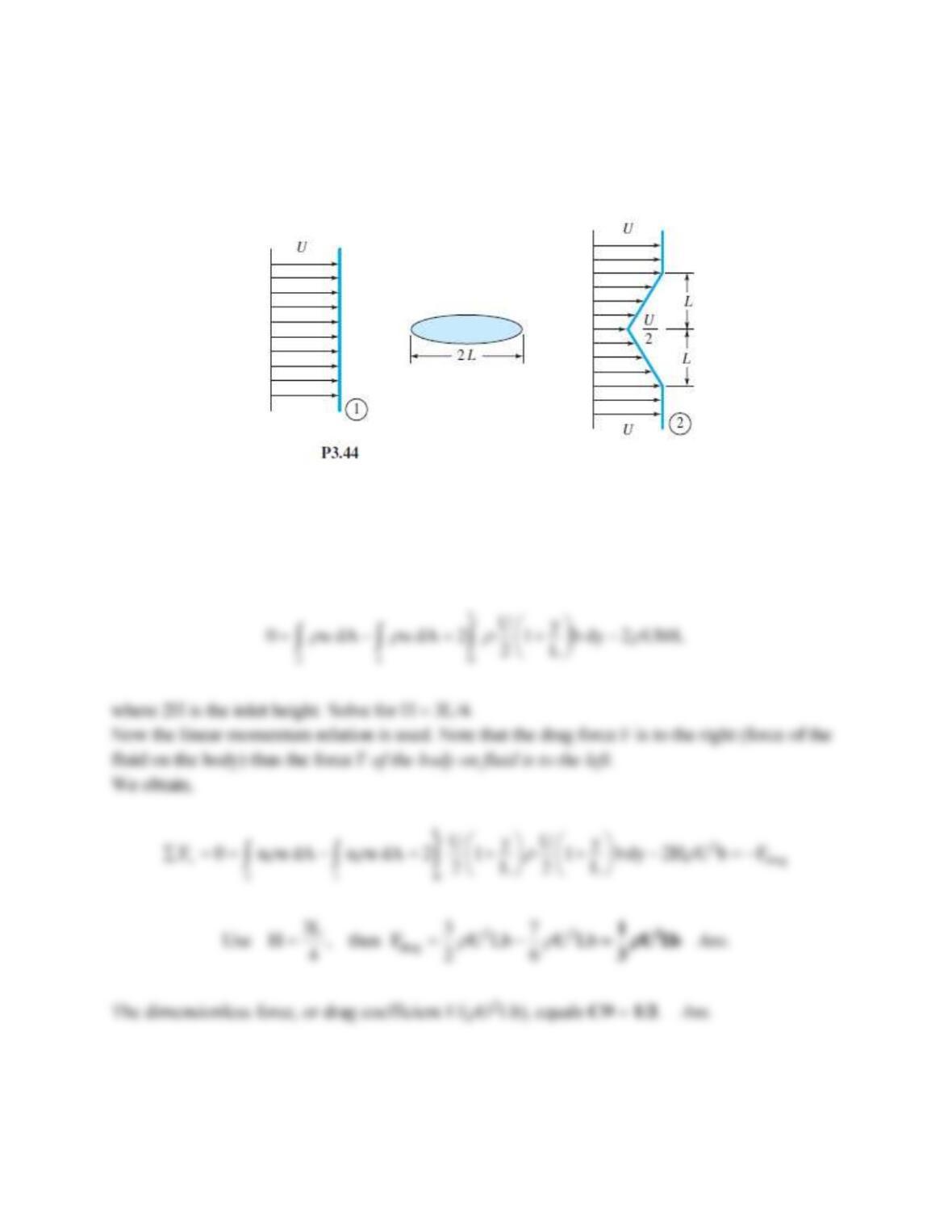
formula for the drag force F on the cylinder. Rewrite your result in the form of a dimensionless
drag coefficient based on body length CD = F/(
U2bL).
Solution 3.44
The proper CV is the entrance (1) and exit (2) plus streamlines above and below which hit
the top and bottom of the wake, as shown. Then steady-flow continuity yields,
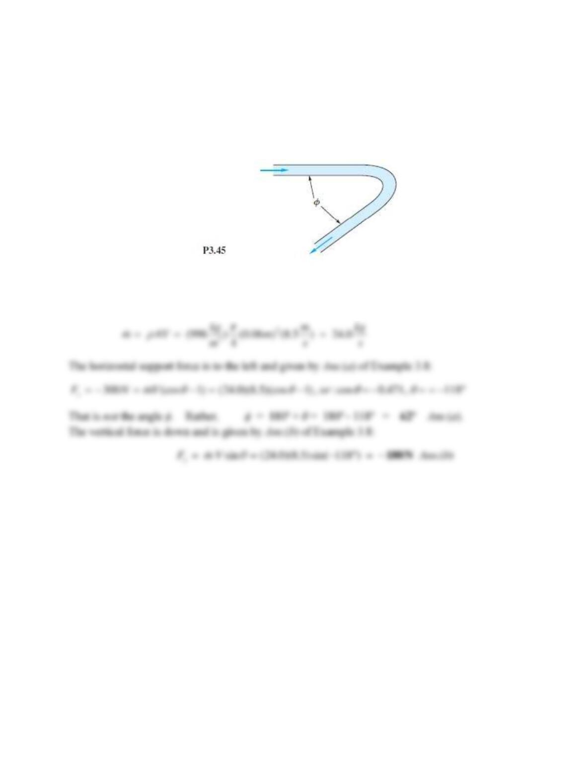
Problem 3.45
Water enters and leaves the 6-cm diameter pipe bend in Fig. P3.45 at an average velocity of
8.5 m/s. The horizontal force to support the bend against momentum change is 300 N. Find
(a) the angle ϕ; and (b) the vertical force on the bend.
Solution 3.45
For water take ρ = 998 kg/m3. The mass flow is
Problem 3.46
When a jet strikes an inclined fixed plate, as in Fig. P3.46, it breaks into two jets at 2 and 3 of
equal velocity V = Vjet but unequal flows αQ at 2 and (1 − α )Q at section 3, α being a fraction.
The reason is that for frictionless flow the fluid can exert no tangential force Ft on the plate. The
condition Ft = 0 enables us to solve for α . Perform this analysis, and find α as a function of the
plate angle θ . Why doesn’t the answer depend on the properties of the jet?


