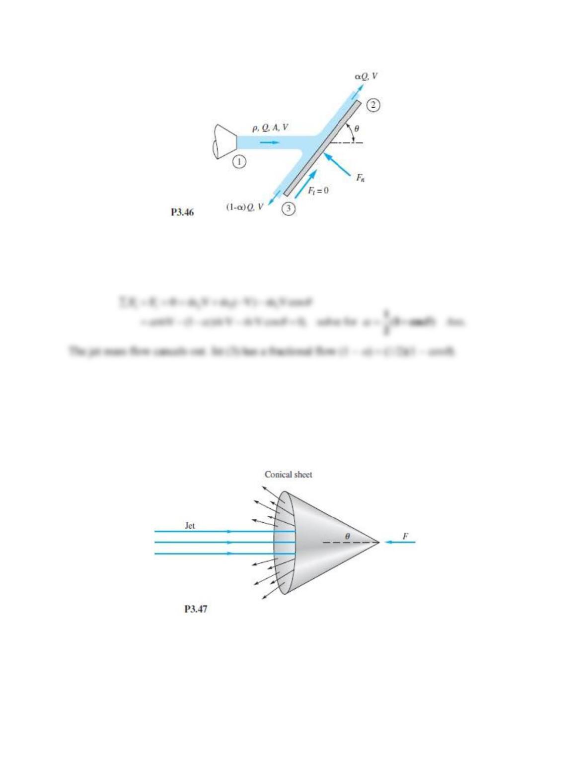
Solution 3.46
Let the CV enclose all three jets and the surface of the plate. Analyze the force and momentum
balance tangential to the plate:
Problem 3.47
A liquid jet Vj of diameter Dj strikes a fixed hollow cone, as in Fig P3.47, and deflects back as a
conical sheet at the same velocity. Find the cone angle
for which the restraining force
F = (3/2)
AjVj2.
Solution 3.47
Let the CV enclose the cone, the jet, and the sheet. Then,
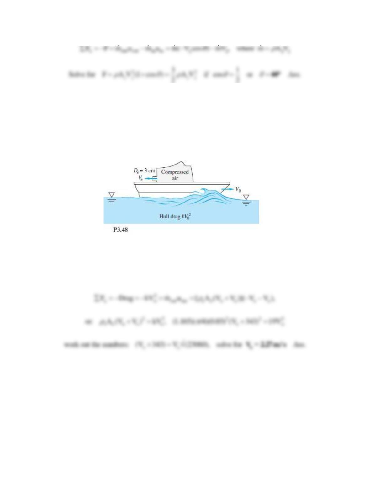
Problem 3.48
The small boat in Fig. P3.48 is driven at a steady speed V0 by a jet of compressed air issuing
from a 3-cm-diameter hole at Ve = 343 m/s. Jet exit conditions are pe = 1 atm and Te = 30°C. Air
drag is negligible, and the hull drag is
2
0
kV
, where k ≈ 19 N · s2/m2 . Estimate the boat speed V0
in m/s.
Solution 3.48
For a CV enclosing the boat and moving to the right at boat speed Vo, the air appears to leave
the left side at speed (Vo + Ve). The air density is pe/RTe 1.165 kg/m3. The only mass flow
across the CS is the air moving to the left. The force balance is
Problem 3.49
The horizontal nozzle in Fig. P3.49 has D1 = 12 in, D2 = 6 in, with p1 = 38 lbf/in2 and
V2 = 56 ft/s. For water at 20°C, compute the horizontal force provided by the flange bolts to hold
the nozzle fixed.
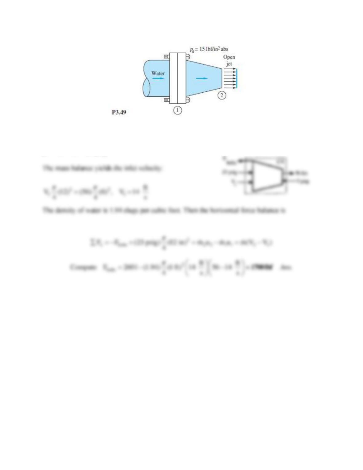
Solution 3.49
For an open jet, p2 = pa = 15 psia. Subtract pa everywhere so the only nonzero pressure is
p1 = 38 − 15 = 23 psig.
Problem 3.50
The jet engine on a test stand in Fig. P3.50 admits air at 20°C and 1 atm at section 1, where
A1 = 0.5 m2 and V1 = 250 m/s. The fuel-to-air ratio is 1:30. The air leaves section 2 at
atmospheric pressure and higher temperature, where V2 = 900 m/s and A2 = 0.4 m2 . Compute the
horizontal test stand reaction Rx needed to hold this engine fixed.
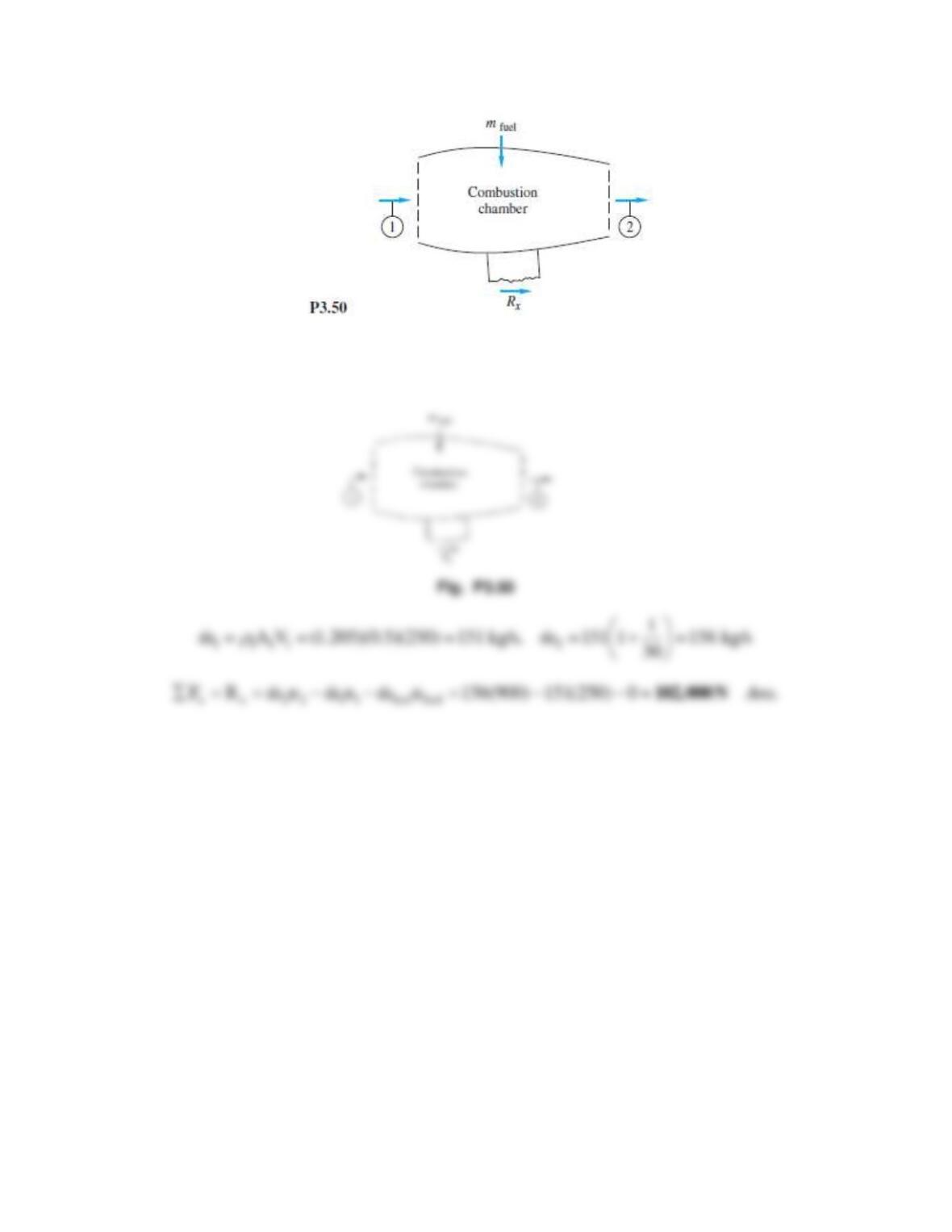
Solution 3.50
1 = p/RT = 101350/[287(293)] = 1.205 kg/m3. For a CV enclosing the engine,
Problem 3.51
A liquid jet of velocity Vj and area Aj strikes a single 180° bucket on a turbine wheel rotating at
angular velocity Ω, as in Fig. P3.51. Derive an expression for the power P delivered to this wheel
at this instant as a function of the system parameters. At what angular velocity is the maximum
power delivered? How would your analysis differ if there were many, many buckets on the
wheel, so that the jet was continually striking at least one bucket?
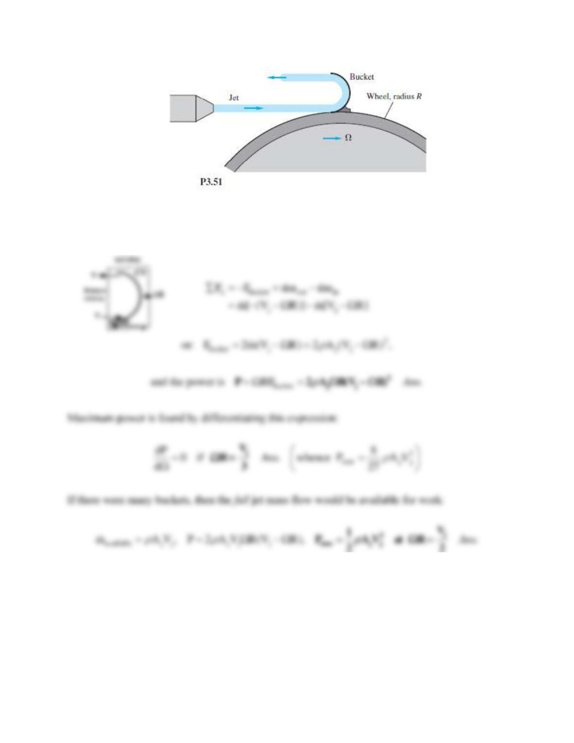
Solution 3.51
Let the CV enclose the bucket and jet and let it move to the right at bucket velocity V = R, so
that the jet enters the CV at relative speed (Vj − R). Then,
Problem 3.52
A large commercial power washer delivers 21 gal/min of water through a nozzle of exit diameter
one-third of an inch. Estimate the force of the water jet on a wall normal to the jet.
Solution 3.52
For water take ρ ≈ 1.94 slug/ft3. Convert 21 gal/min ÷ 448.83 = 0.0468 ft3/s. Then
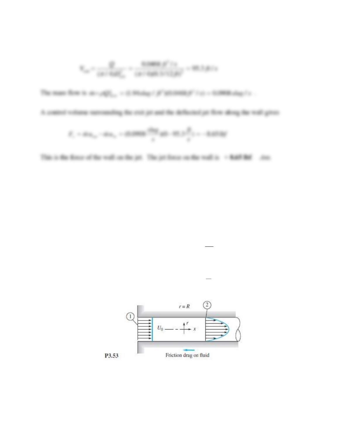
Problem 3.53
Consider incompressible flow in the entrance of a circular tube, as in Fig. P3.53. The inlet flow is
uniform, u1 = Uo. The flow at section 2 is developed pipe flow. Find the wall drag force F as a
function of (p1, p2,
, Uo, R) if the flow at section 2 is
2
2 max 2
(a) Laminar: 1 r
uu
R
=−
1/7
2 max
(b) Turbulent: 1 r
uu
R
−
Solution 3.53
The CV encloses the inlet and outlet and is just inside the walls of the tube. We don’t need to
establish a relation between umax and Uo by integration, because the results for these two
profiles are given in the text. Note that Uo = uav at section (2). Now use these results as needed
for the balance of forces:
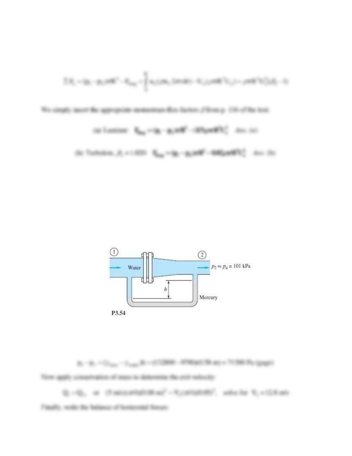
Problem 3.54
For the pipe-flow reducing section of Fig. P3.54, D1 = 8 cm, D2 = 5 cm, and p2 = 1 atm. All fluids
are at 20°C. If V1 = 5 m/s and the manometer reading is h = 58 cm, estimate the total horizontal
force resisted by the flange bolts.
Solution 3.54
Let the CV cut through the bolts and through section 2. For the given manometer reading, we
may compute the upstream pressure:
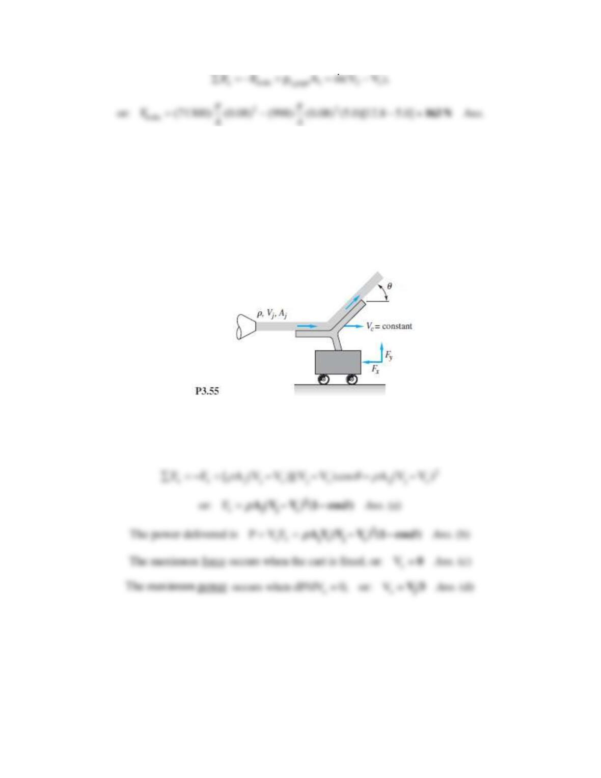
Problem 3.55
In Fig. P3.55 the jet strikes a vane which moves to the right at constant velocity Vc on a
frictionless cart. Compute (a) the force Fx required to restrain the cart and (b) the power P
delivered to the cart. Also find the cart velocity for which (c) the force Fx is a maximum and
(d) the power P is a maximum.
Solution 3.55
Let the CV surround the vane and cart and move to the right at cart speed. The jet strikes the
vane at relative speed Vj − Vc. The cart does not accelerate, so the horizontal force balance is
Problem 3.56
Water at 20°C flows steadily through the box in Fig. P3.56, entering station (1) at 2 m/s.
Calculate the (a) horizontal; and (b) vertical forces required to hold the box stationary against the
flow momentum.
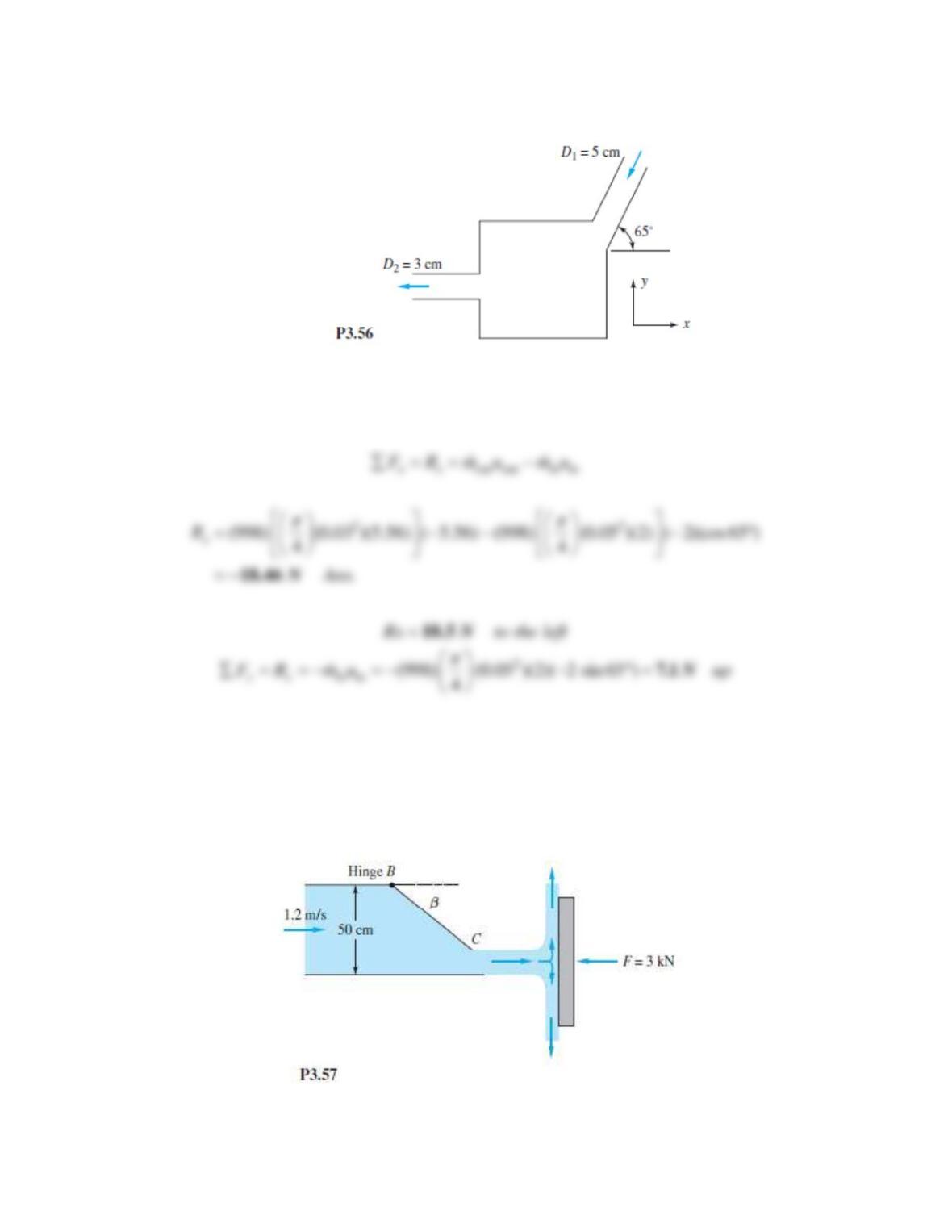
Solution 3.56
(a) Summing horizontal forces,
Problem 3.57
Water flows through the duct in Fig. P3.57, which is 50 cm wide and 1 m deep into the paper.
Gate BC completely closes the duct when
= 90°. Assuming one-dimensional flow, for what
angle
will the force of the exit jet on the plate be 3 kN?
Solution 3.57
The steady flow equation applied to the duct, Q1 = Q2, gives the jet velocity as
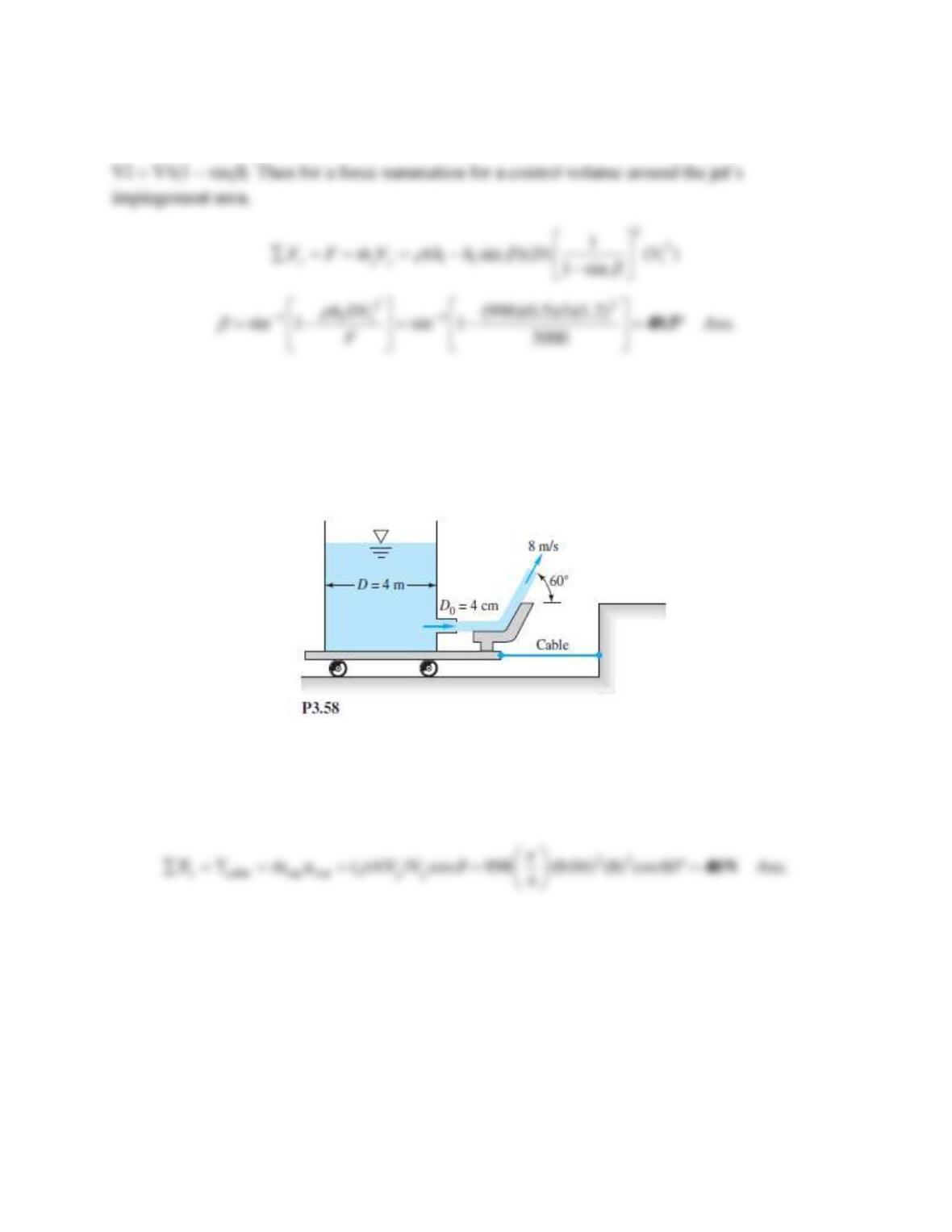
Problem 3.58
The water tank in Fig. P3.58 stands on a frictionless cart and feeds a jet of diameter 4 cm and
velocity 8 m/s, which is deflected 60° by a vane. Compute the tension in the supporting cable.
Solution 3.58
The CV should surround the tank and wheels and cut through the cable and the exit water jet.
Then the horizontal force balance is
Problem 3.59
When a pipe flow suddenly expands from A1 to A2 , as in Fig. P3.59, low-speed, low-friction
eddies appear in the corners and the flow gradually expands to A2 downstream. Using the
suggested control volume for incompressible steady flow and assuming that p ≈ p1 on the corner
annular ring as shown, show that the downstream pressure is given by
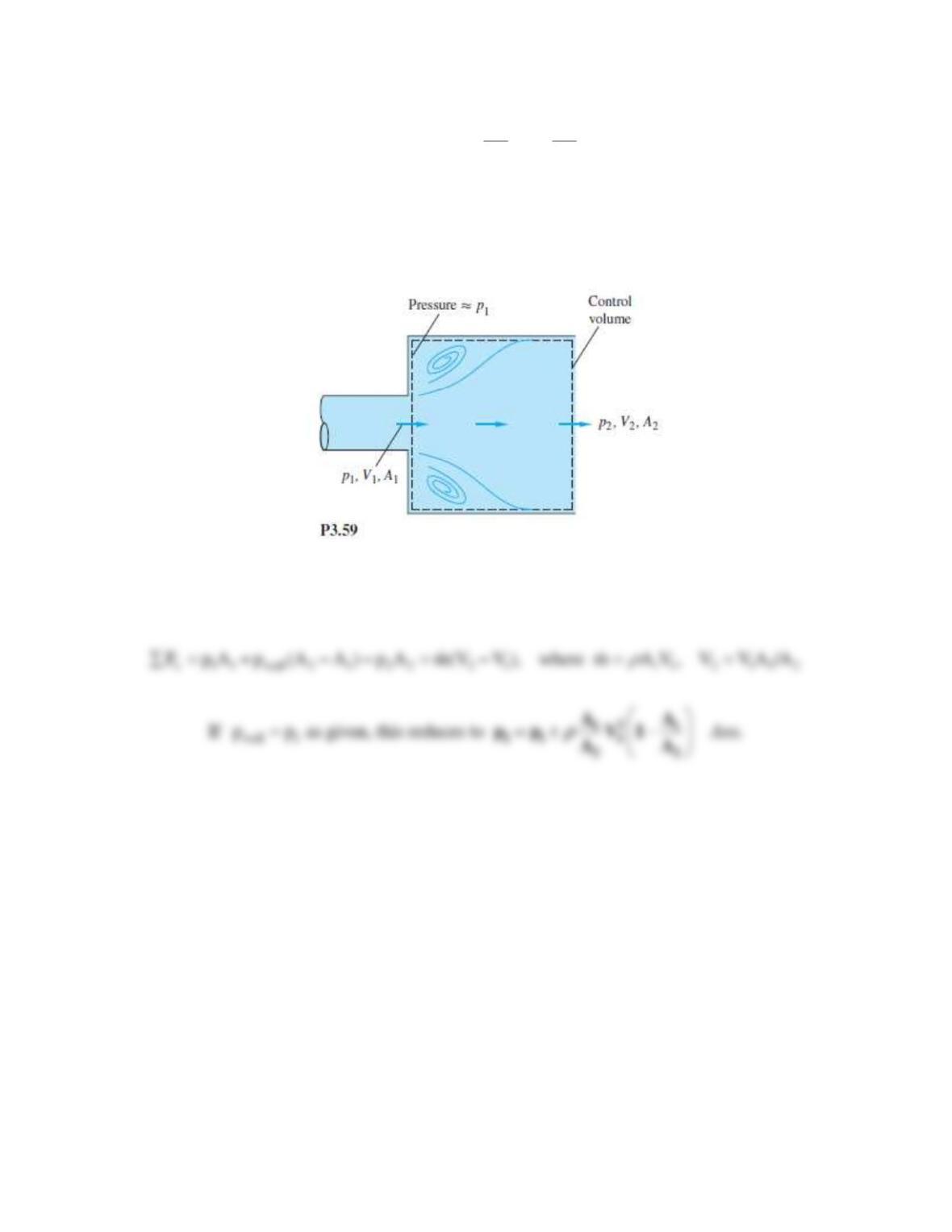
Neglect wall friction.
Solution 3.59
From mass conservation, V1A1 = V2A2. The balance of x-forces gives
Problem 3.60
Water at 20°C flows through the elbow in Fig. P3.60 and exits to the atmosphere. The pipe
diameter is D1 = 10 cm, while D2 = 3 cm. At a weight flow rate of 150 N/s, the pressure
p1 = 2.3 atm (gage). Neglecting the weight of water and elbow, estimate the force on the flange
bolts at section 1.
211
2 1 1
22
AA
p p V 1
AA
= + −
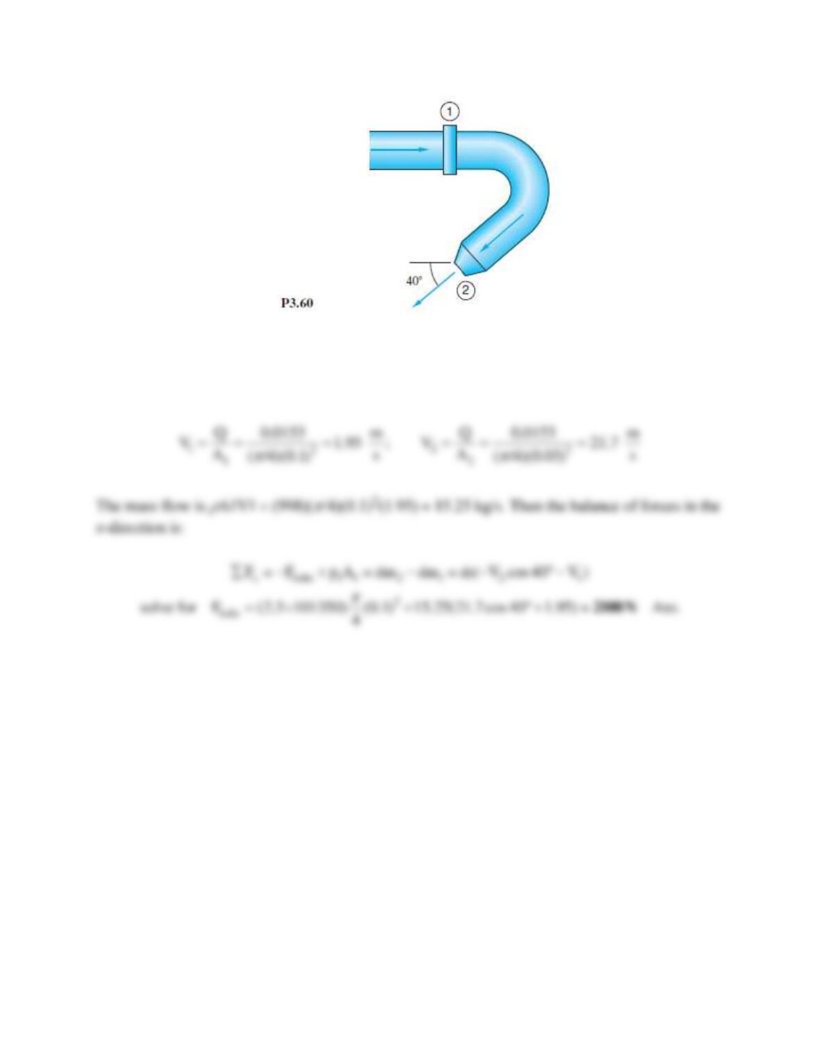
Solution 3.60
First, from the weight flow, compute Q = (150 N/s)/(9790 N/m3) = 0.0153 m3/s. Then the
velocities at (1) and (2) follow from the known areas:
Problem 3.61
A 20°C water jet strikes a vane mounted on a tank with frictionless wheels, as in Fig. P3.61. The
jet turns and falls into the tank without spilling out. If θ = 30° , evaluate the horizontal force F
required to hold the tank stationary.
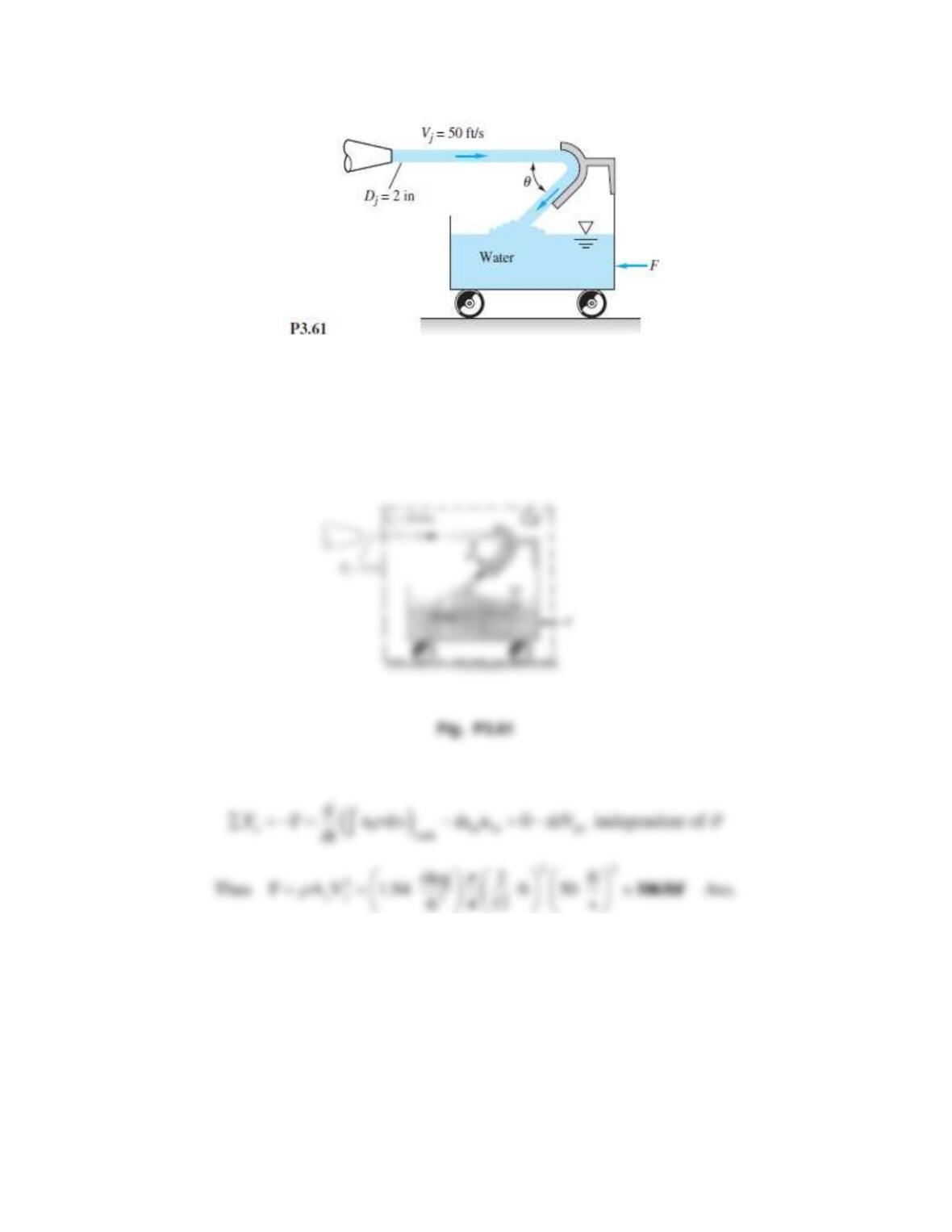
Solution 3.61
The CV surrounds the tank and wheels and cuts through the jet, as shown. We should assume
that the splashing into the tank does not increase the x-momentum of the water in the tank. Then
we can write the CV horizontal force relation:
Problem 3.62
Water at 20°C exits to the standard sea-level atmosphere through the split nozzle in Fig. P3.62.
Duct areas are A1 = 0.02 m2 and A2 = A3 = 0.008 m2. If p1 = 135 kPa (absolute) and the flow rate
is Q2 = Q3 = 275 m3/h, compute the force on the flange bolts at section 1.
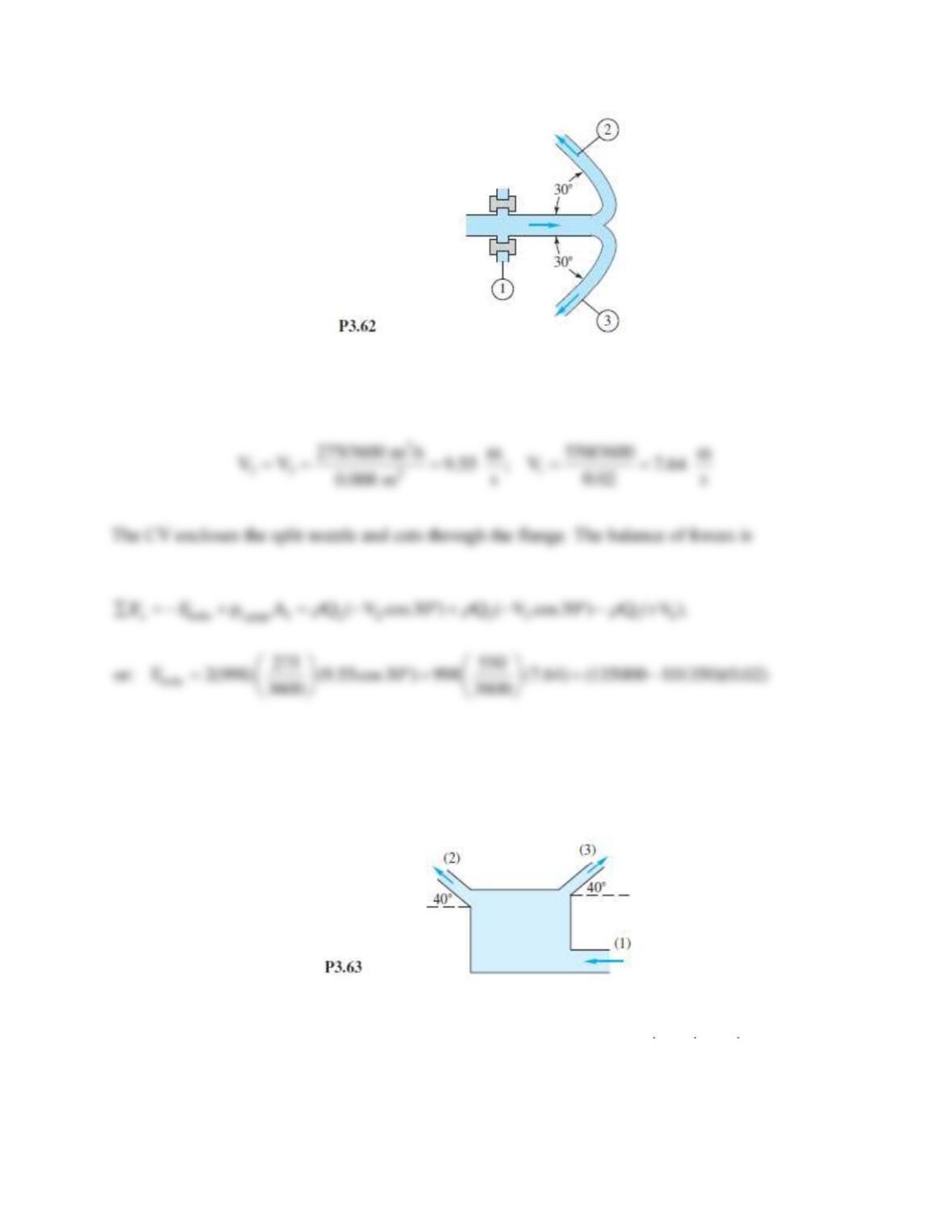
Solution 3.62
With the known flow rates, we can compute the various velocities:
Problem 3.63
Water flows steadily through the box in Fig. P3.63. Average velocity at all ports is 7 m/s. The
vertical momentum force on the box is 36 N. What is the inlet mass flow?
Solution 3.63
We don’t need water density, just mass flow. Continuity requires that
1 2 3
m m m=+
, and then,
with a control volume around the entire system, steady vertical momentum requires that
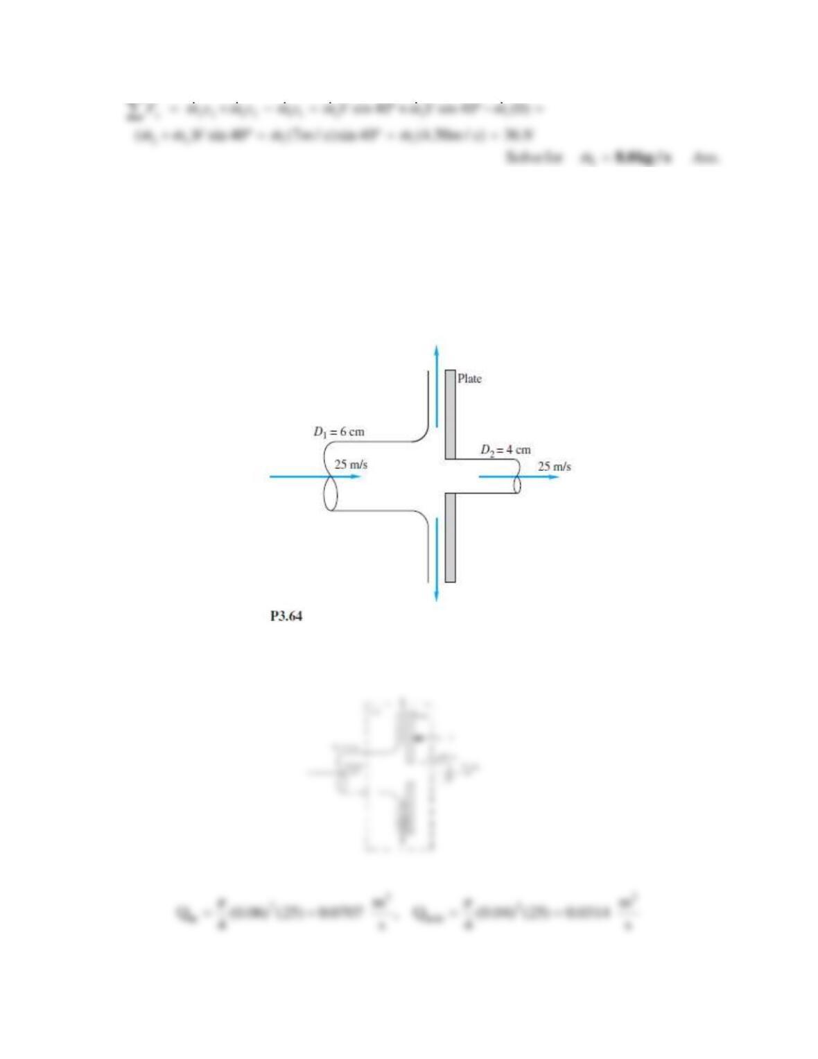
Problem 3.64
The 6-cm-diameter 20°C water jet in Fig. P3.64 strikes a plate containing a hole of 4-cm
diameter. Part of the jet passes through the hole, and part is deflected. Determine the horizontal
force required to hold the plate.
Solution 3.64
First determine the incoming flow and the flow through the hole:
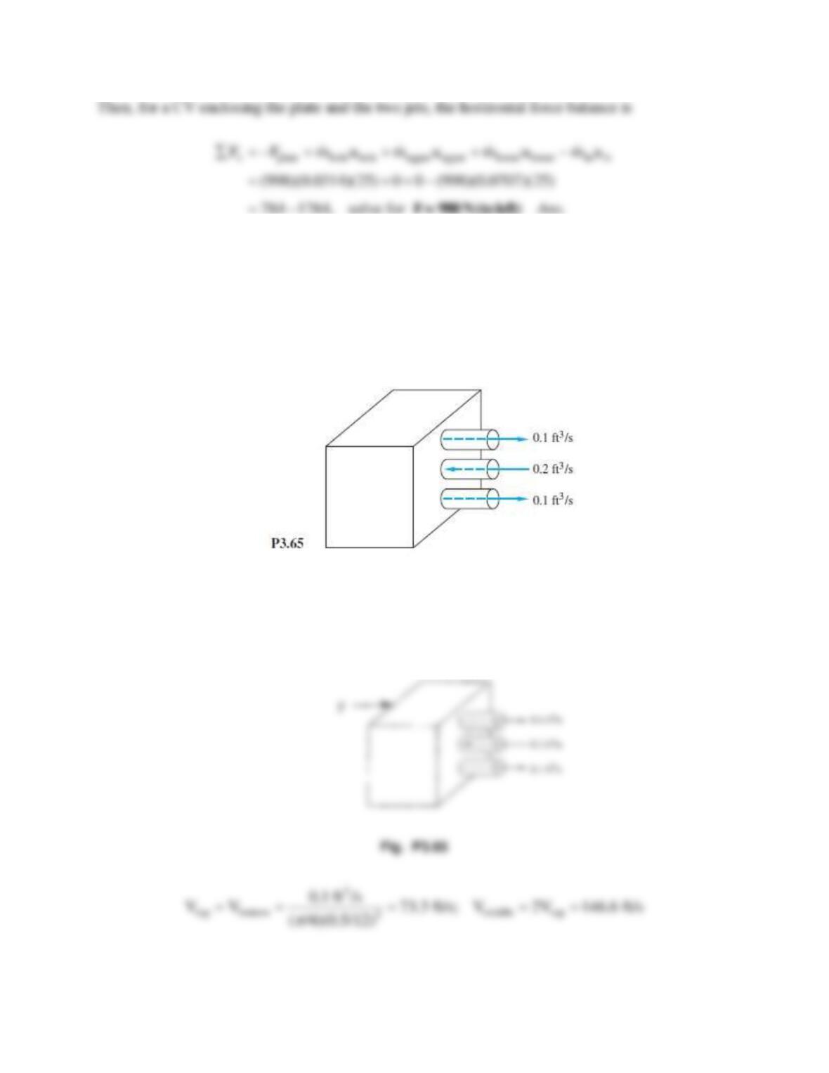
Problem 3.65
The box in Fig. P3.65 has three 0.5-in holes on the right side. The volume flows of 20°C water
shown are steady, but the details of the interior are not known. Compute the force, if any, which
this water flow causes on the box.
Solution 3.65
First we need to compute the velocities through the various holes:
box
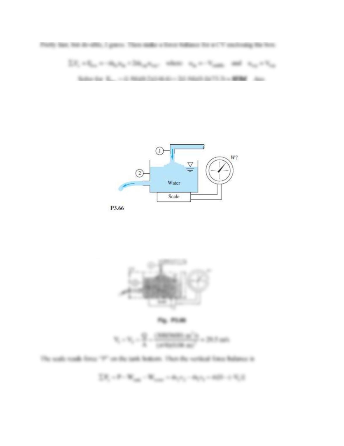
Problem 3.66
The tank in Fig. P3.66 weighs 500 N empty and contains 600 L of water at 20°C. Pipes 1 and 2
have equal diameters of 6 cm and equal steady volume flows of 300 m3/h. What should the scale
reading W be in N?
Solution 3.66
Let the CV surround the tank, cut through the two jets, and slip just under the tank bottom, as
shown. The relevant jet velocities are
Problem 3.67
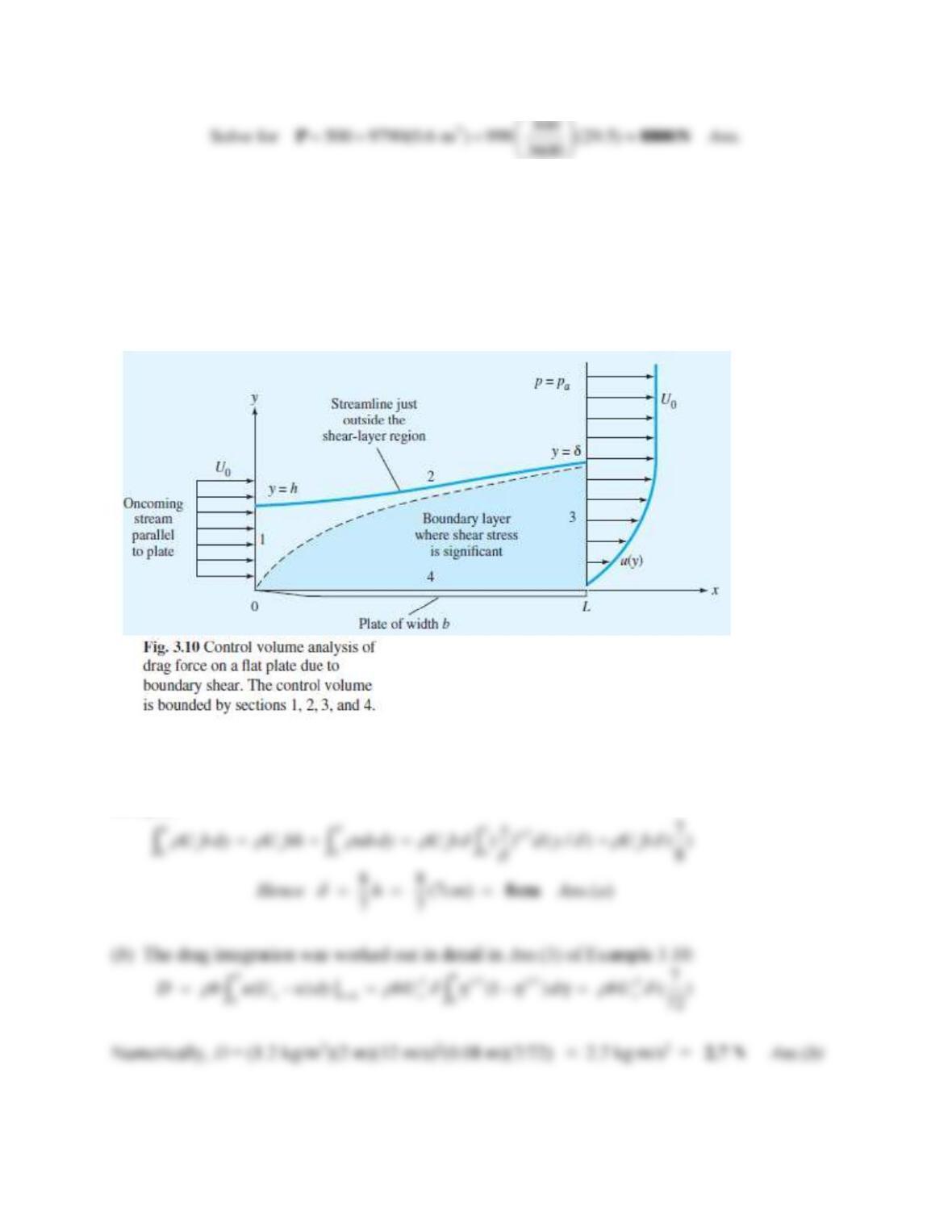
For the boundary layer of Fig. 3.10, for air, ρ = 1.2 kg/m3, let h = 7 cm, Uo = 12 m/s, b = 2 m,
and L = 1 m. Let the velocity at the exit, x = L, approximate a turbulent flow:
1/7
/ ( / ) .
o
u U y
Calculate (a) δ ; and (b) the friction drag D.
Solution 3.67
(a) Since the upper and lower boundaries are stream-surfaces, the inlet and exit mass flows must
be equal:
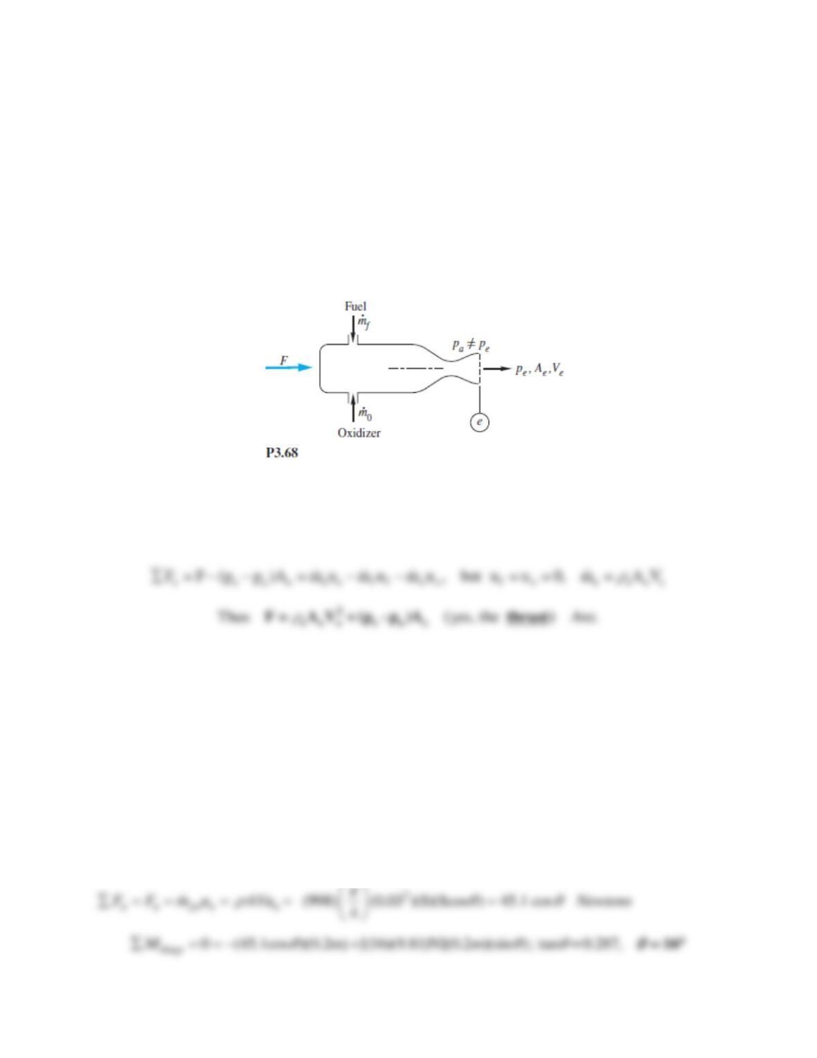
Problem 3.68
The rocket in Fig. P3.68 has a super-sonic exhaust, and the exit pressure pe is not necessarily
equal to pa. Show that the force F required to hold this rocket on the test stand is
F =
eAeVe2 + Ae(pe − pa).
Is this force F what we term the thrust of the rocket?
Solution 3.68
The appropriate CV surrounds the entire rocket and cuts through the exit jet. Subtract pa
everywhere so only exit pressure 0. The horizontal force balance is
Problem 3.69
A uniform rectangular plate, 40 cm long and 30 cm deep into the paper, hangs in air from a hinge
at its top, (the 30-cm side). It is struck in its center by a horizontal 3-cm-diameter jet of water
moving at 8 m/s. If the gate has a mass of 16 kg, estimate the angle at which the plate will hang
from the vertical.
Solution 3.69
The plate orientation can be found through force and moment balances. Find the force normal to
the plate:
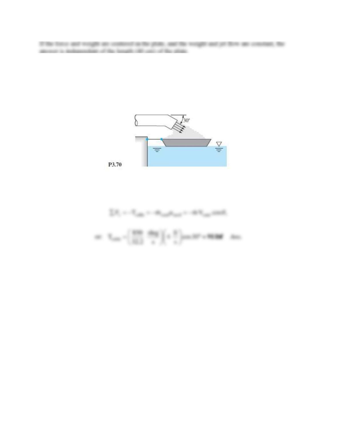
Problem 3.70
The dredger in Fig. P3.70 is loading sand (SG = 2.6) onto a barge. The sand leaves the dredger
pipe at 4 ft/s with a weight flux of 850 lbf/s. Estimate the tension on the mooring line caused by
this loading process.
Solution 3.70
The CV encloses the boat and cuts through the cable and the sand flow jet. Then,
Problem 3.71
Suppose that a deflector is deployed at the exit of the jet engine of Prob. 3.50, as shown in Fig.
P3.71. What will the reaction Rx on the test stand be now? Is this reaction sufficient to serve as a
braking force during airplane landing?