Solution 11.86
Convert P* = 447 kW = 599 hp. Then, for D = 36 = 3.0 ft,
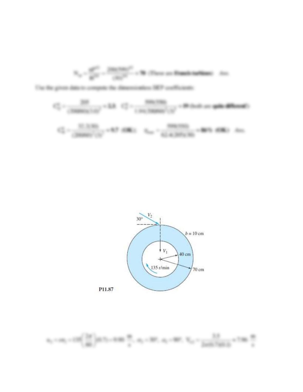
Problem 11.87
An idealized radial turbine is shown in Fig. P11.87. The absolute flow enters at 30 and leaves
radially inward. The flow rate is 3.5 m3/s of water at 20C. The blade thickness is constant at
10 cm. Compute the theoretical power developed.
Solution 11.87
For water, take
998 kg/m3. With reference to Fig. 11.22 and Eq. 11.35,
Problem 11.88
Performance data for a very small (D = 8.25 cm) model water turbine, operating with an
available head of 49 ft, are as follows:
Q, m3/h:
18.7
18.7
18.5
18.3
17.6
16.7
15.1
11.5
rpm:
0
500
1000
1500
2000
2500
3000
3500
0
14%
27%
38%
50%
65%
61%
11%
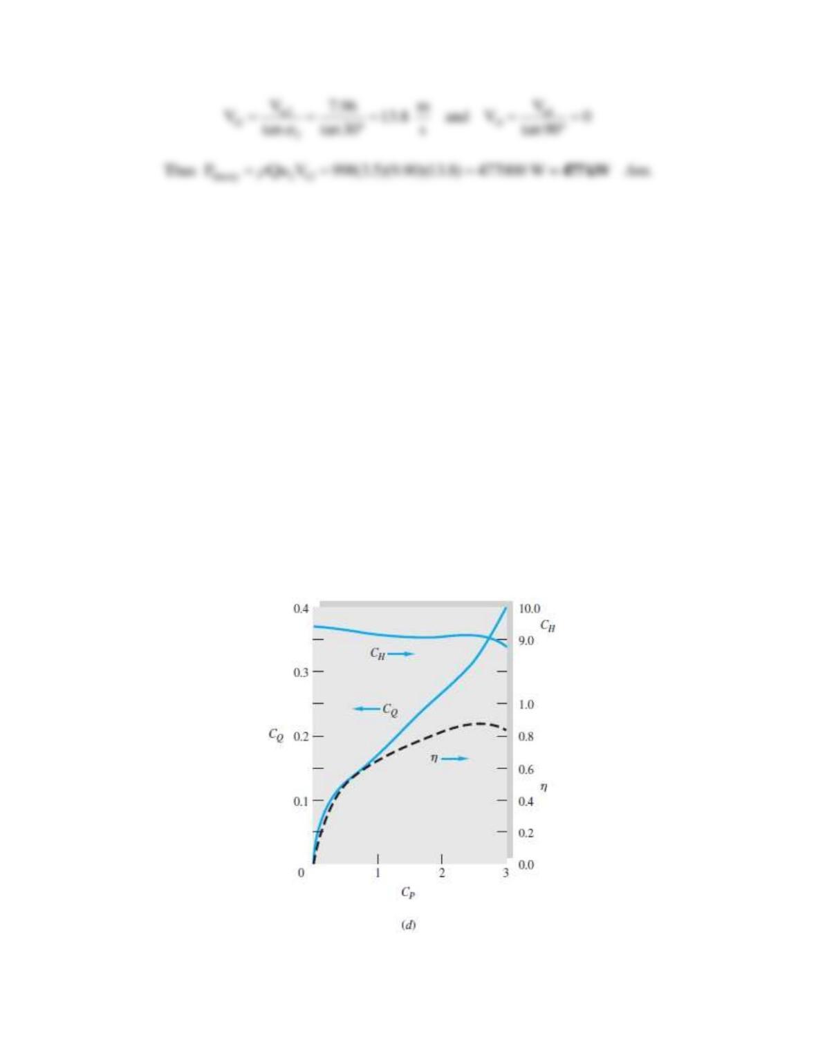
(a) What type of turbine is this likely to be? (b) What is so different about this data compared to
the dimensionless performance plot in Fig. 11.22d? Suppose it is desired to use a geometrically
similar turbine to serve where the available head and flow are 150 ft and 6.7 ft3/s, respectively.
Estimate the most efficient (c) turbine diameter; (d) rotation speed; and (e) horsepower.
Figure 11.22.d:
Solution 11.88
(a) Convert Q = 16.7 m3/h = 0.164 ft3/s. Use BEP data to calculate power specific speed:
Problem 11.89
A Pelton wheel of 12-ft pitch diameter operates under a new head of 2000 ft. Estimate the speed,
power output, and flow rate for best efficiency if the nozzle exit diameter is 4 in.
Solution 11.89
First get the jet velocity and then assume BEP at
0.47:
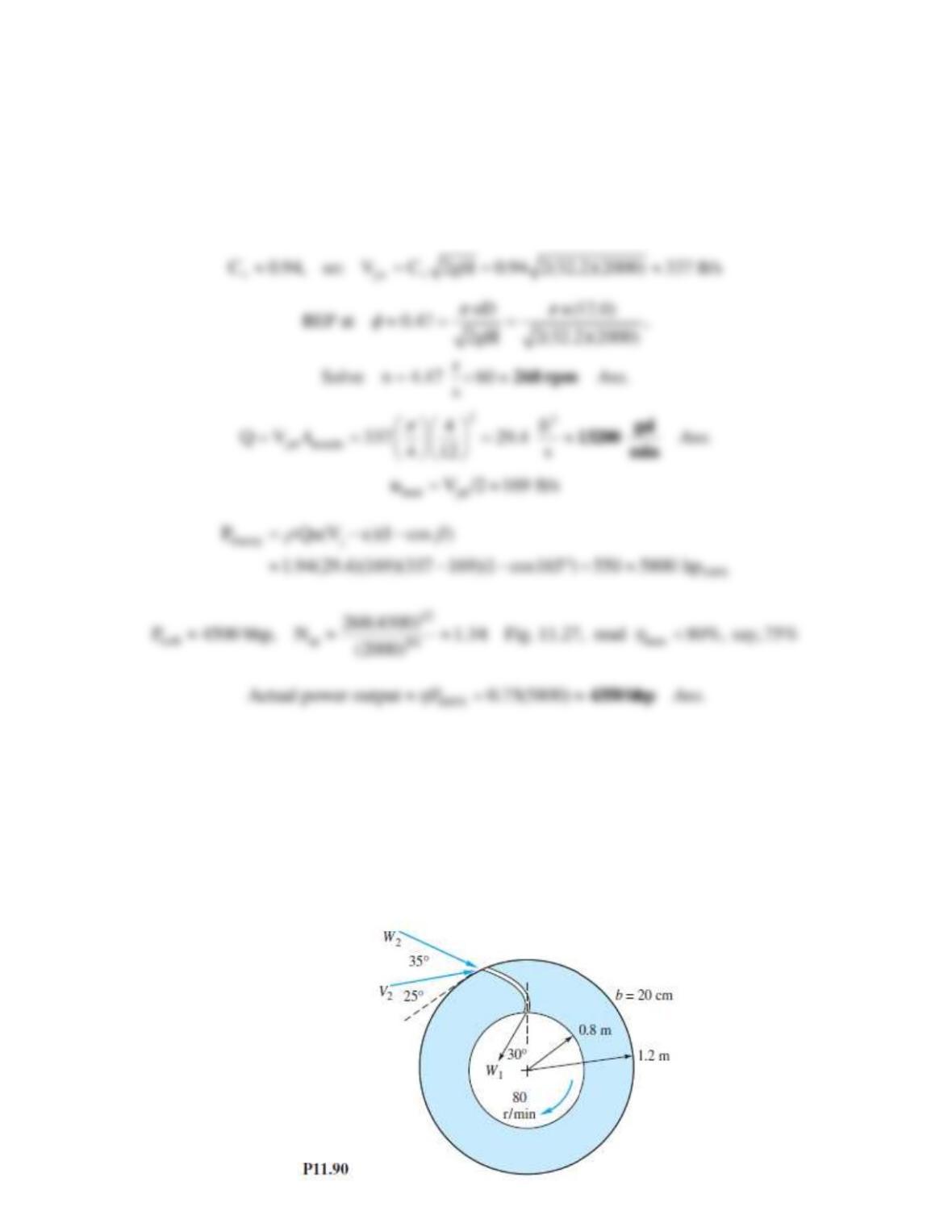
Problem 11.90
An idealized radial turbine is shown in Fig. P11.90. The absolute flow enters at 25 with the
blade angles as shown. The flow rate is 8 m3/s of water at 20C. The blade thickness is
constant at 20 cm. Compute the theoretical power developed.
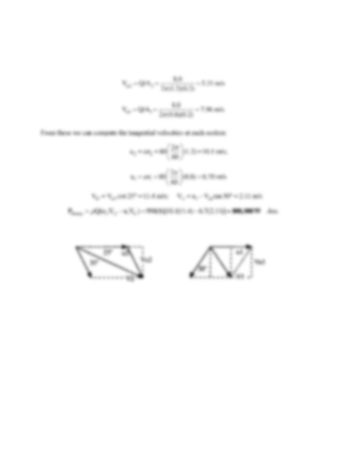
Solution 11.90
The inlet (2) and outlet (1) velocity vector diagrams are shown at right. The normal velocities are
Problem 11.91
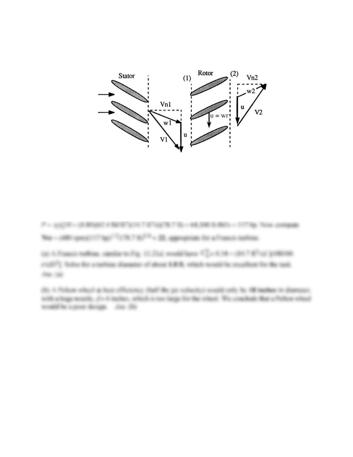
The flow through an axial-flow turbine can be idealized by modifying the stator-rotor diagrams
of Fig. 11.12 for energy absorption. Sketch a suitable blade and flow arrangement and the
associated velocity vector diagrams.
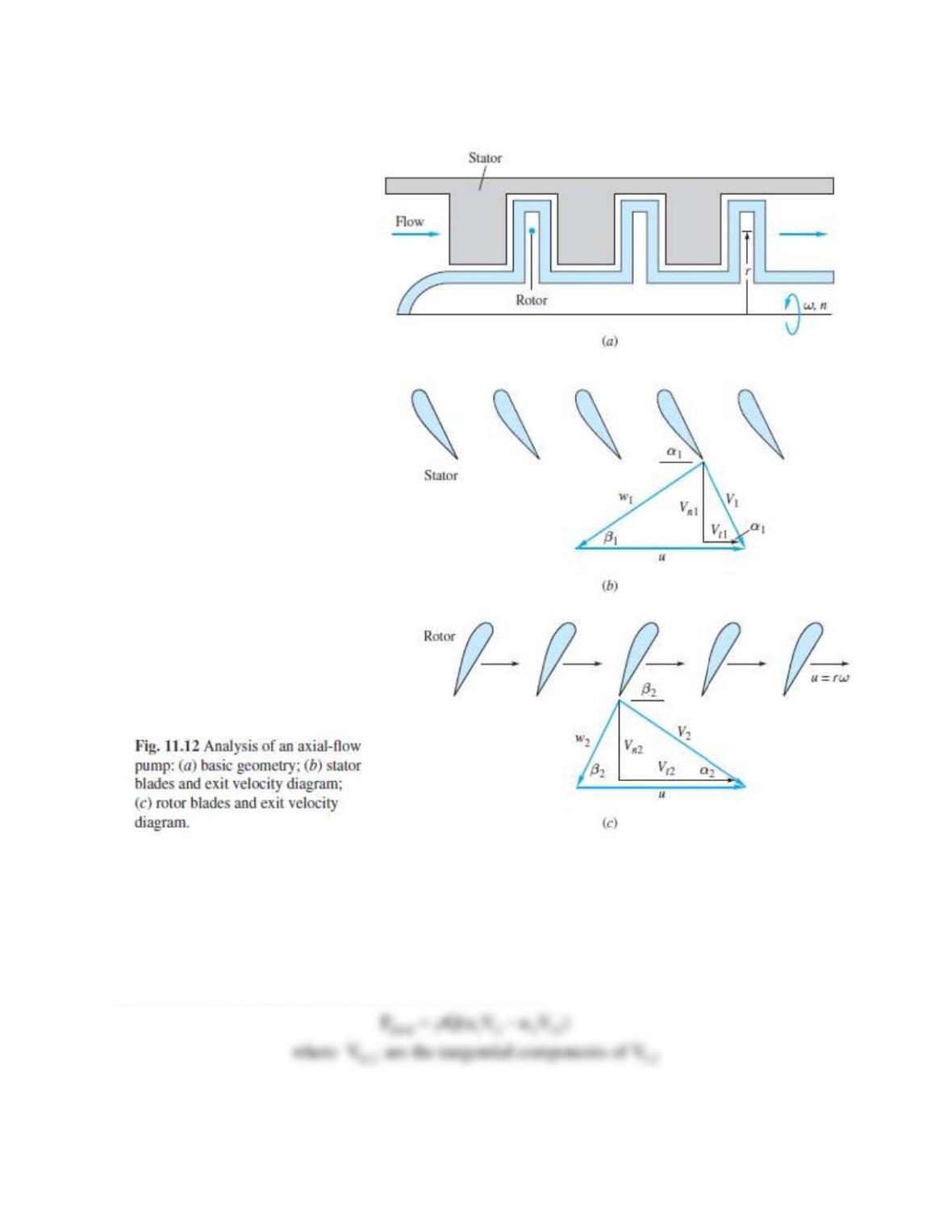
Solution 11.91
Some typical velocity diagrams are shown below, where u =
r = blade speed. The power
delivered to the turbine, at 100% ideal shock-free flow, is
Problem 11.92
A dam on a river is being sited for a hydraulic turbine. The flow rate is 1500 m3/h, the available
head is 24 m, and the turbine speed is to be 480 r/min. Discuss the estimated turbine size and
feasibility for (a) a Francis turbine; and (b) a Pelton wheel.
Solution 11.92
Assume
89%, as in Fig. 11.21d. The power generated by the turbine would be
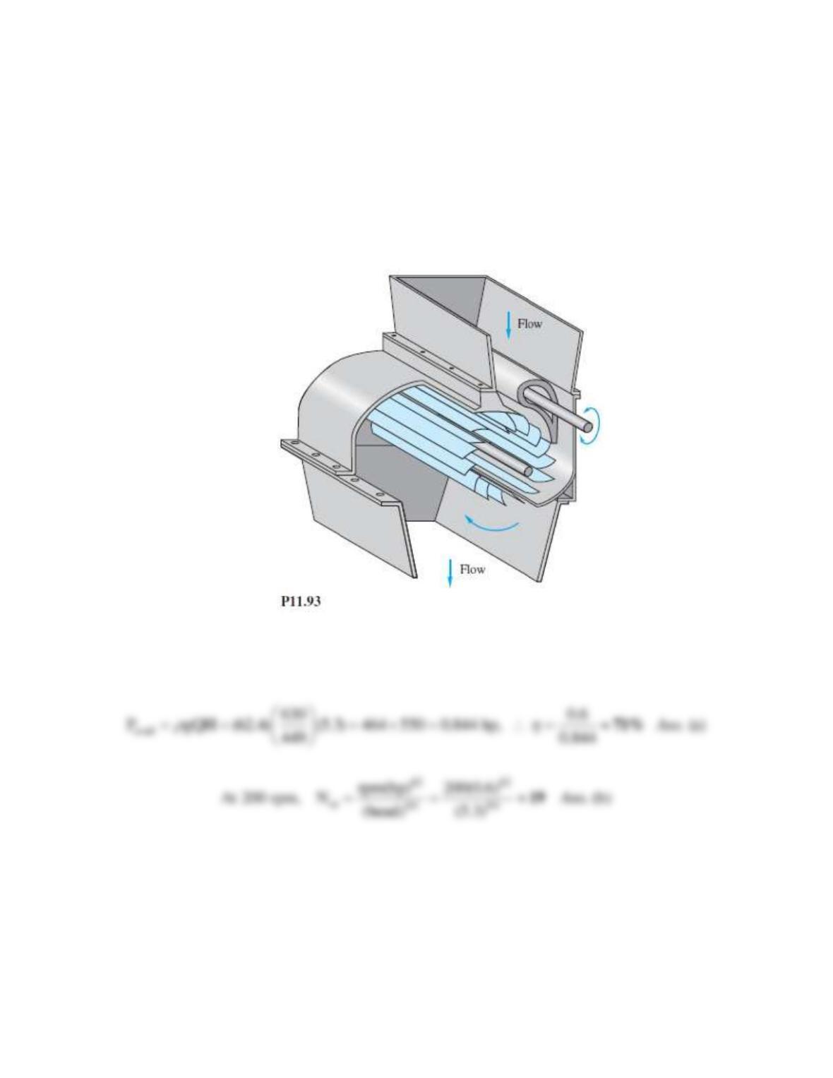
Problem 11.93
Figure P11.93, shown below, is a crossflow or “Banki” turbine [55], which resembles a squirrel
cage with slotted curved blades. The flow enters at about 2 o’clock and passes through the center
and then again through the blades, leaving at about 8 o’clock. Report to the class on the
operation and advantages of this design, including idealized velocity vector diagrams.
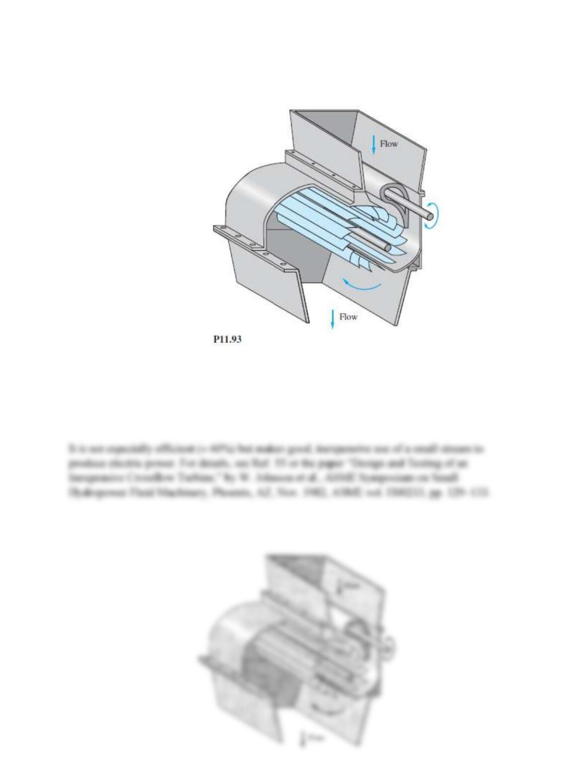
Solution 11.93
Brief Discussion (not a “Solution”):The crossflow turbine is ideal for small dam owners,
because of its simple, inexpensive design. It can easily be constructed by a novice (such as the
writer) from wood and plastic.
Problem 11.94
A simple crossflow turbine, Fig. P11.93 above, was constructed and tested at the University of
Rhode Island. The blades were made of PVC pipe cut lengthwise into three 120-arc pieces.
When it was tested in water at a heads of 5.3 ft and a flow rate of 630 gal/min, the measured
power output was 0.6 hp. Estimate (a) the efficiency; and (b) the power specific speed if
n = 200 r/min.
Solution 11.94
We have sufficient information to compute the available water power:
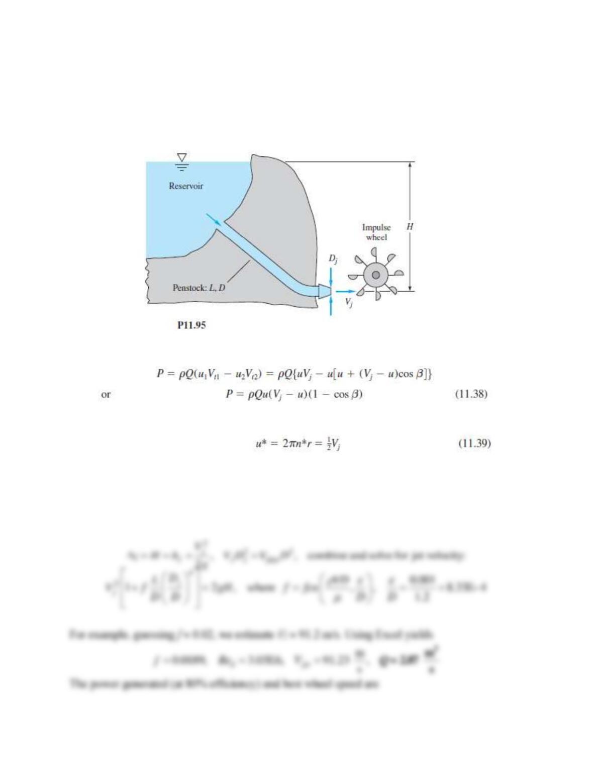
Problem 11.95*
One can make a theoretical estimate of the proper diameter for a penstock in an impulse turbine
installation, as in Fig. P11.95. Let L and H be known, and let the turbine performance be
idealized by Eqs. (11.38) and (11.39). Account for friction loss hf in the penstock, but neglect
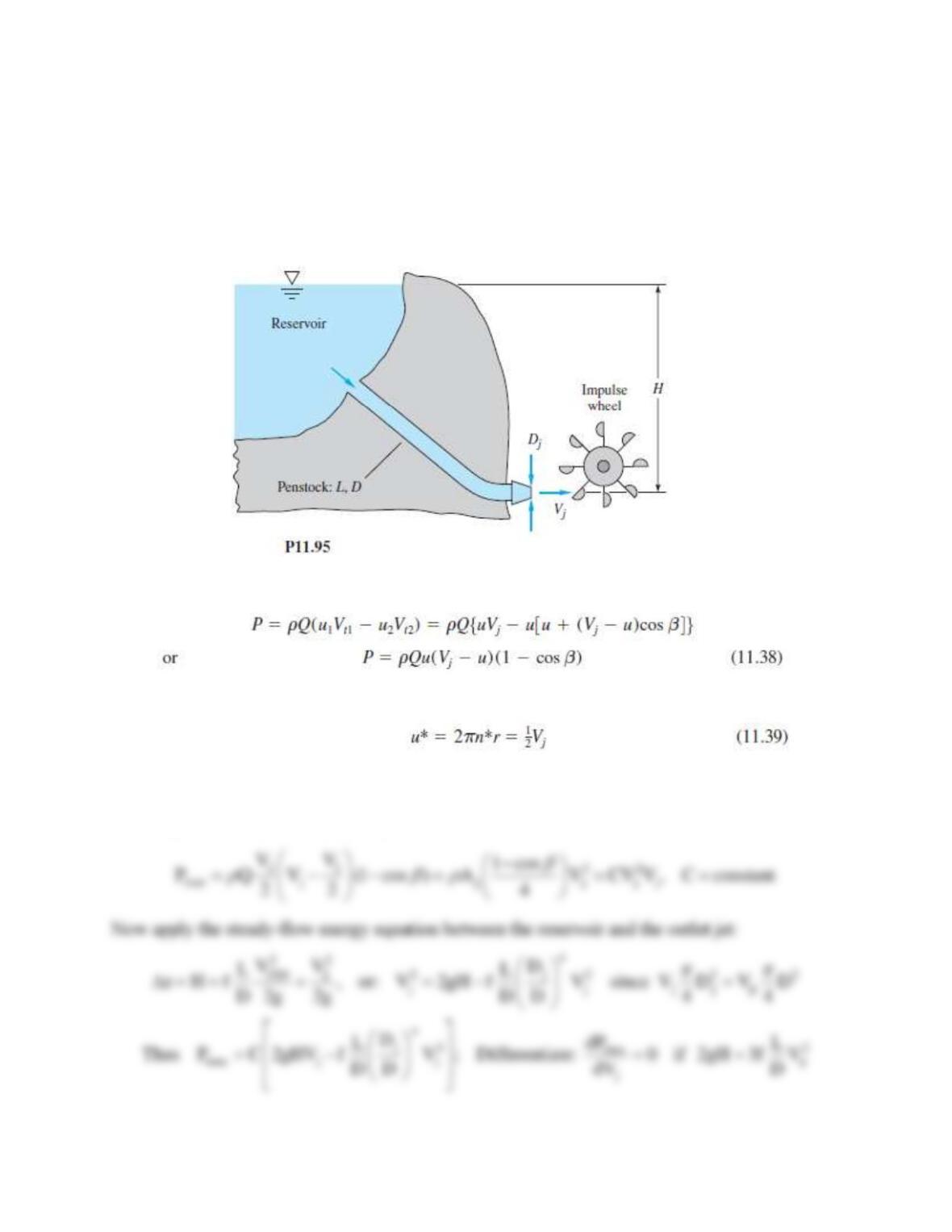
minor losses. Show that (a) the maximum power is generated when hf = H/3, (b) the optimum jet
velocity is (4gH/3)1/2, and (c) the best nozzle diameter is Dj = [D5/(2fL)]1/4, where f is the pipe-
friction factor.
Solution 11.95
From Eqs. 11.38 and 39, maximum power is obtained when u = Vj/2, or:
Problem 11.96
Apply the results of Prob. P11.95 to determine the optimum (a) penstock diameter and (b) nozzle
diameter for a head of 330 m and a flow rate of 5400 m3/h with a cast iron penstock of length
600 m.
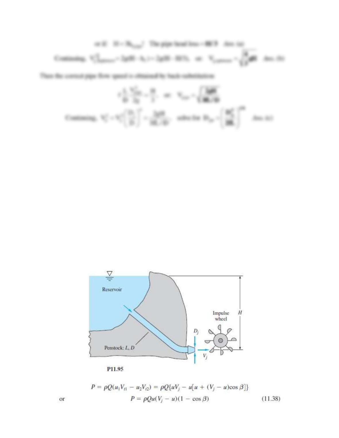
Problem 11.95*
One can make a theoretical estimate of the proper diameter for a penstock in an impulse turbine
installation, as in Fig. P11.95. Let L and H be known, and let the turbine performance be
idealized by Eqs. (11.38) and (11.39). Account for friction loss hf in the penstock, but neglect
minor losses. Show that (a) the maximum power is generated when hf = H/3, (b) the optimum jet
velocity is (4gH/3)1/2, and (c) the best nozzle diameter is Dj = [D5/(2fL)]1/4, where f is the pipe-
friction factor.
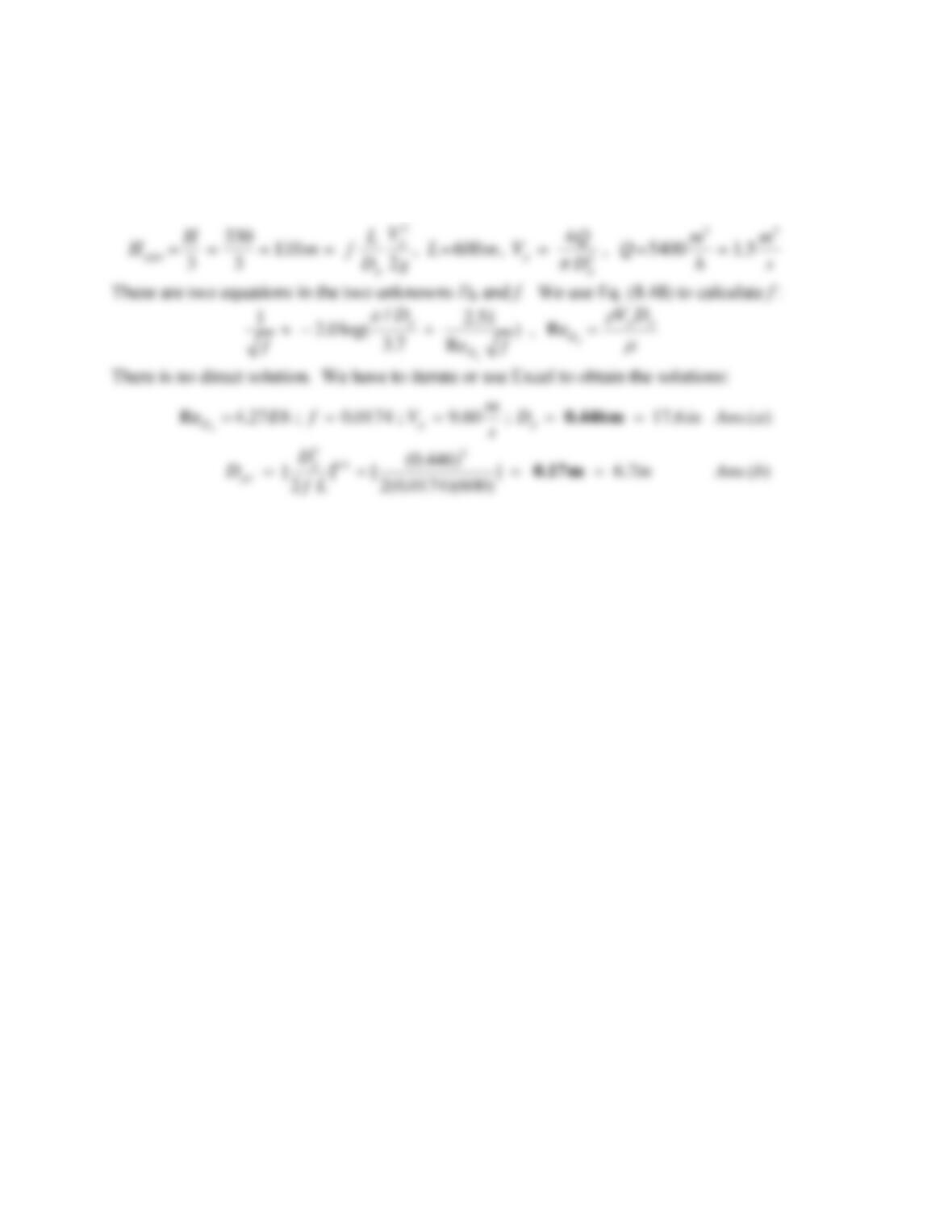
Solution 11.96
For water take ρ = 998 kg/m3 and μ = 0.0010 kg/(m·s). For cast iron take ε = 0.26 mm.
Prob. P11.95 showed that the optimum friction head loss is H/3:
Problem 11.97
Consider the following nonoptimum version of Prob. 11.95: H = 450 m, L = 5 km, D = 1.2 m,
Dj = 20 cm. The penstock is concrete,
= 1 mm. The impulse wheel diameter is 3.2 m. Estimate
(a) the power generated by the wheel at 80 percent efficiency; and (b) the best speed of the wheel
in r/min. Neglect minor losses.
Problem 11.95*
One can make a theoretical estimate of the proper diameter for a penstock in an impulse turbine
installation, as in Fig. P11.95. Let L and H be known, and let the turbine performance be
idealized by Eqs. (11.38) and (11.39). Account for friction loss hf in the penstock, but neglect
minor losses. Show that (a) the maximum power is generated when hf = H/3, (b) the optimum jet
velocity is (4gH/3)1/2, and (c) the best nozzle diameter is Dj = [D5/(2fL)]1/4, where f is the pipe-
friction factor
Solution 11.97
For water take
= 998 kg/m3 and
= 0.001 kg/m·s. This is a non-optimum condition, so we
simply make a standard energy and continuity analysis. Refer to the figure on the next page for
the notation: