
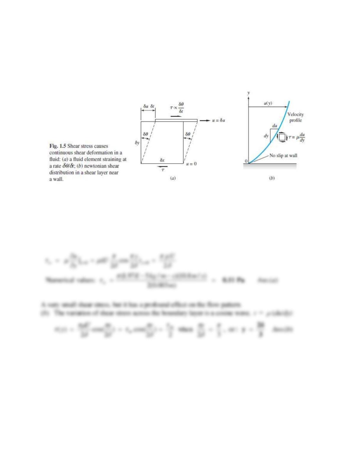
Knowing
for air at 20°C from Table 1.4, estimate its viscosity at 500°C by (a) the power-law,
(b) the Sutherland law. Also make an estimate from (c) Figure 1.6. Compare with the accepted
value
3.58E−5 kg/m · s.
Solution 1.39
First change T from 500°C to 773 K. (a) For the power-law for air, n 0.7, and from Eq. (1.30a),
Problem 1.40
Glycerin at 20ºC fills the space between a hollow sleeve of diameter12 cm and a fixed coaxial
solid rod of diameter 11.8 cm. The outer sleeve is rotated at 120 rev/min. Assuming no
temperature change, estimate the torque required, in N∙m per meter of rod length, to hold the
inner rod fixed.
Solution 1.40
From Table A.3, the viscosity of glycerin is 1.49 kg/(m∙s). The clearance C is the difference in
radii, 6 cm – 5.9 cm = 0.1 cm = 1 mm. The velocity of the sleeve surface is
Problem 1.41
An aluminum cylinder weighing 30 N, 6 cm in diameter and 40 cm long, is falling concentrically
through a long vertical sleeve of diameter 6.04 cm. The clearance is filled with SAE 50 oil at
20C. Estimate the terminal (zero acceleration) fall velocity. Neglect air drag and assume a
linear velocity distribution in the oil. HINT: You are given diameters, not radii.
Solution 1.41
From Table A.3 for SAE 50 oil,
= 0.86 kg/m-s. The clearance is the difference in radii:
Problem 1.42
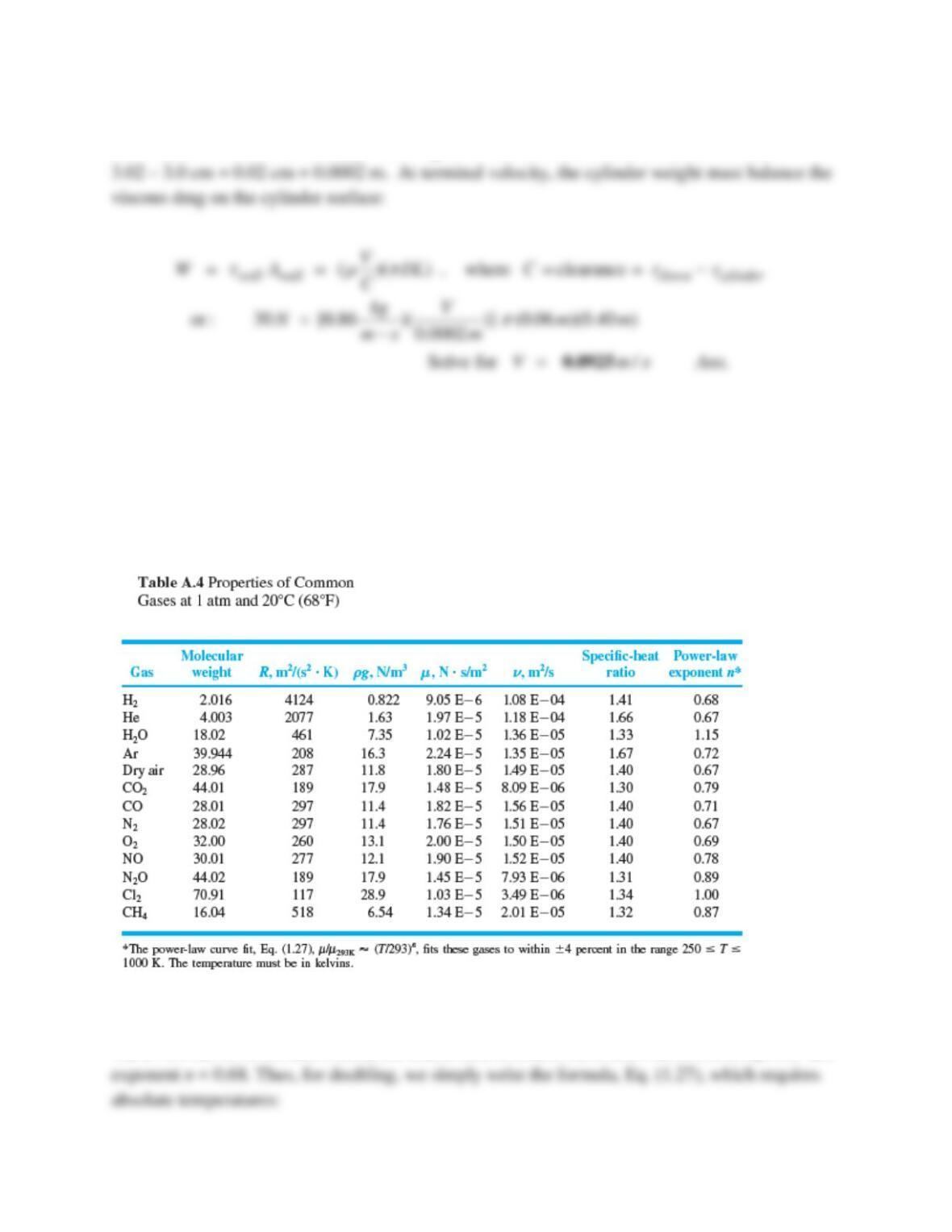
Helium at 20ºC has a viscosity of 1.97E-5 kg/(m∙s). Use the data of Table A.4 to estimate the
temperature, in ºC, at which helium’s viscosity will double.
Solution 1.42
Table A.4 has no information about the Sutherland constant, but it does recommend a power-law
o
Problem 1.43
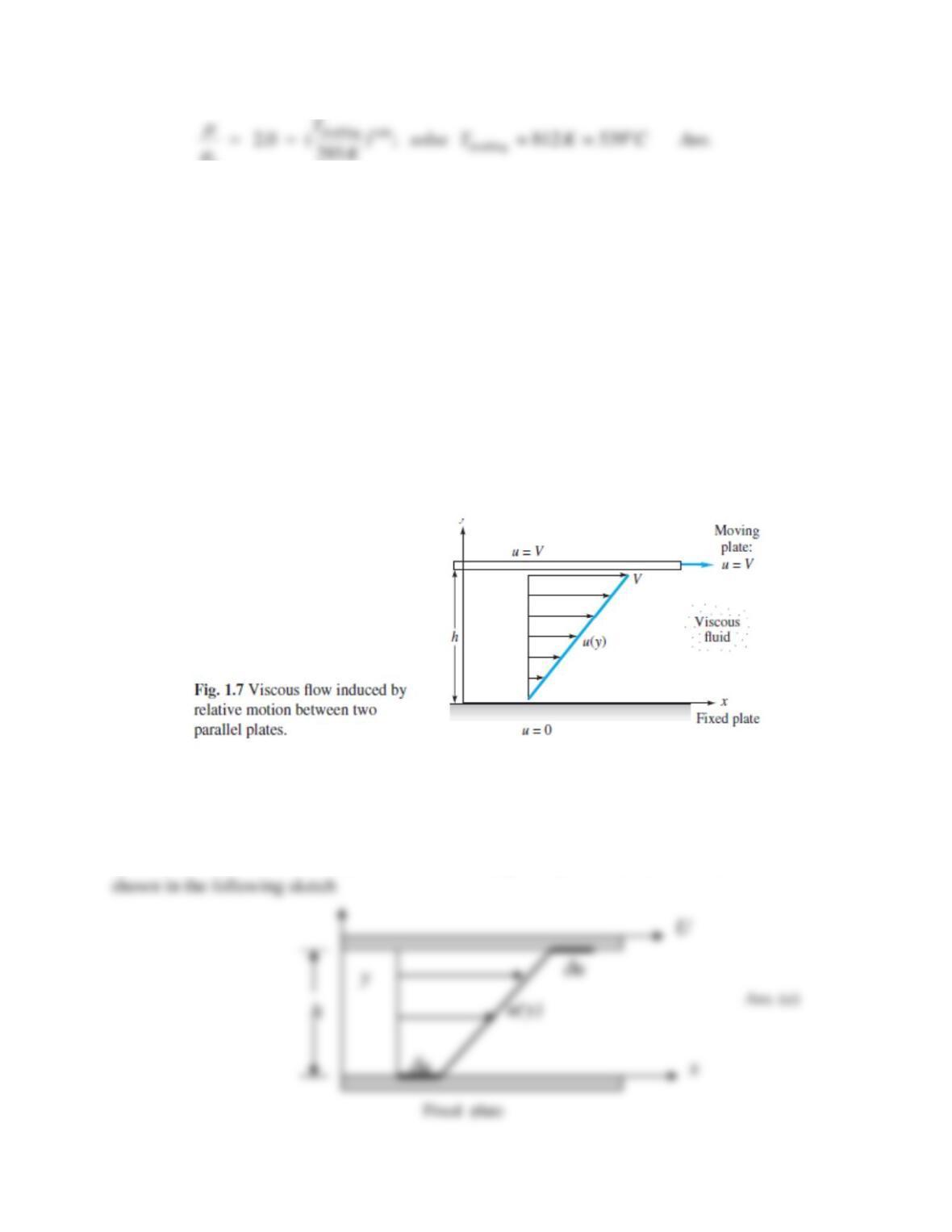
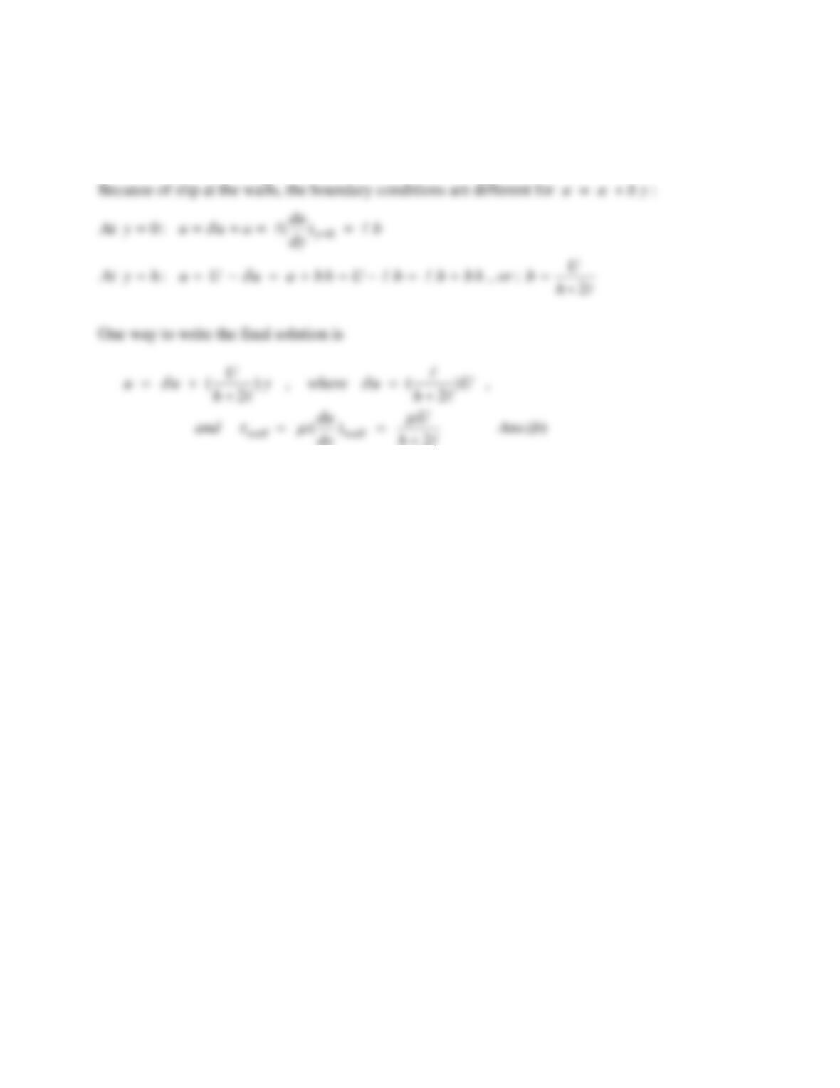
For the flow of gas between two parallel plates of Fig. 1.7, reanalyze for the case of slip flow at
both walls. Use the simple slip condition,
uwall = l (du/dy)wall,
where l is the mean free path of the fluid. Sketch the expected velocity profile and find an
expression for the shear stress at each wall.
Solution 1.43
As in Fig. 1.8, the shear stress remains constant between the two plates. The analysis is correct
up to the relation u = a + b y . There would be equal slip velocities,
u, at both walls, as
Problem 1.44
One type of viscometer is simply a long capillary tube. A commercial device is shown in Prob.
C1.10. One measures the volume flow rate Q and the pressure drop Δp and, of course, the radius
and length of the tube. The theoretical formula, which will be discussed in Chap. 6, is
4
8 / ( )p QL R
. For a capillary of diameter 4 mm and length 10 inches, the test fluid flows
at 0.9 m3/h when the pressure drop is 58 lbf/in2. Find the predicted viscosity in kg/m∙s.
Problem C1.10
A popular gravity-driven instrument is the Cannon-Ubbelohde viscometer, shown in Fig. C1.10.
The test liquid is drawn up above the bulb on the right side and allowed to drain by gravity
through the capillary tube below the bulb. The time t for the meniscus to pass from upper to
lower timing marks is recorded. The kinematic viscosity is computed by the simple formula
= Ct, where C is a calibration constant. For
in the range of 100-500 mm2/s, the
recommended constant is C = 0.50 mm2/s2, with an accuracy less than 0.5%.
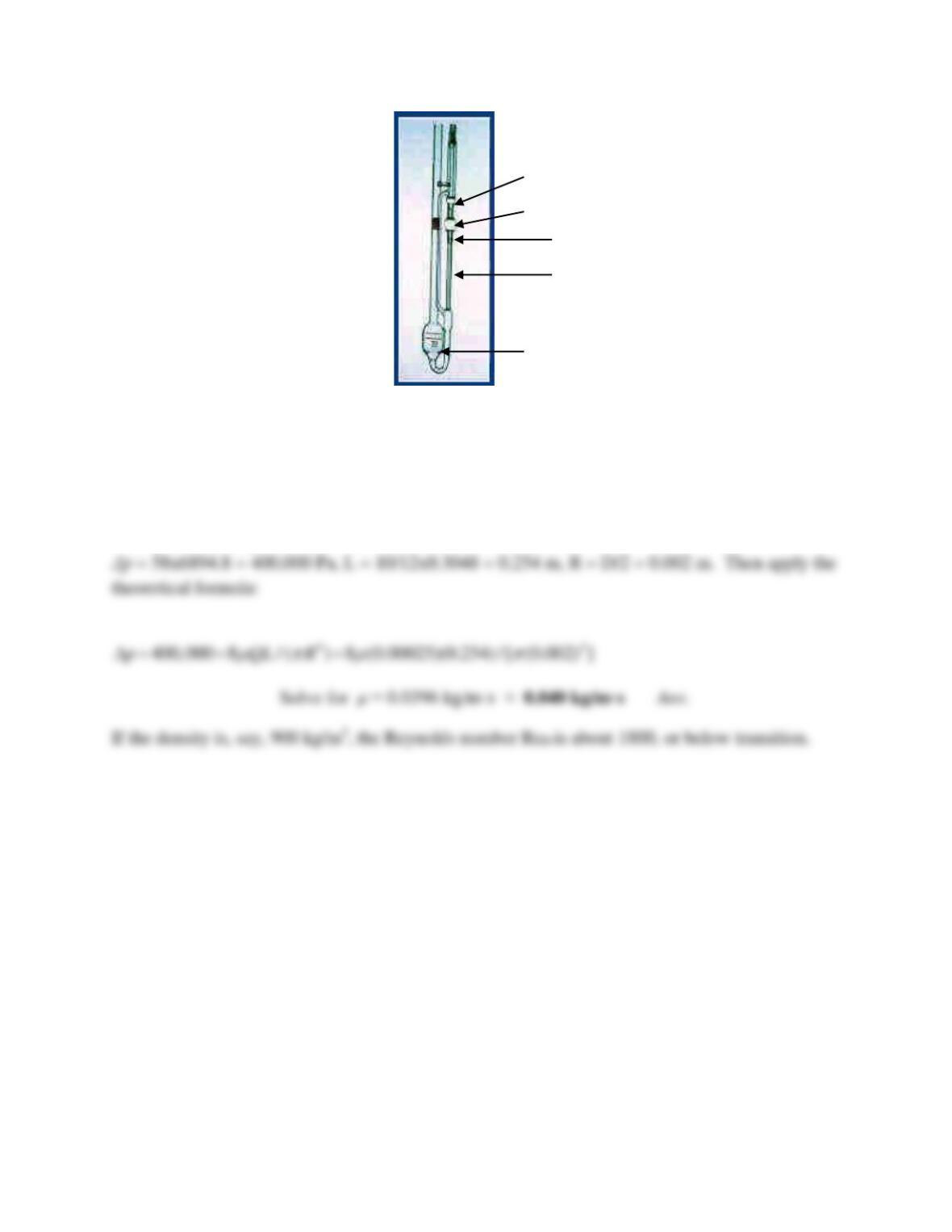
(a) What liquids from Table A.3 are in this viscosity range? (b) Is the calibration formula
dimensionally consistent? (c) What system properties might the constant C depend upon?
(d) What problem in this chapter hints at a formula for estimating the viscosity?
Solution 1.44
Convert everything to SI units: Q = 0.9/3600 = 0.00025 m3/s,
Problem 1.45
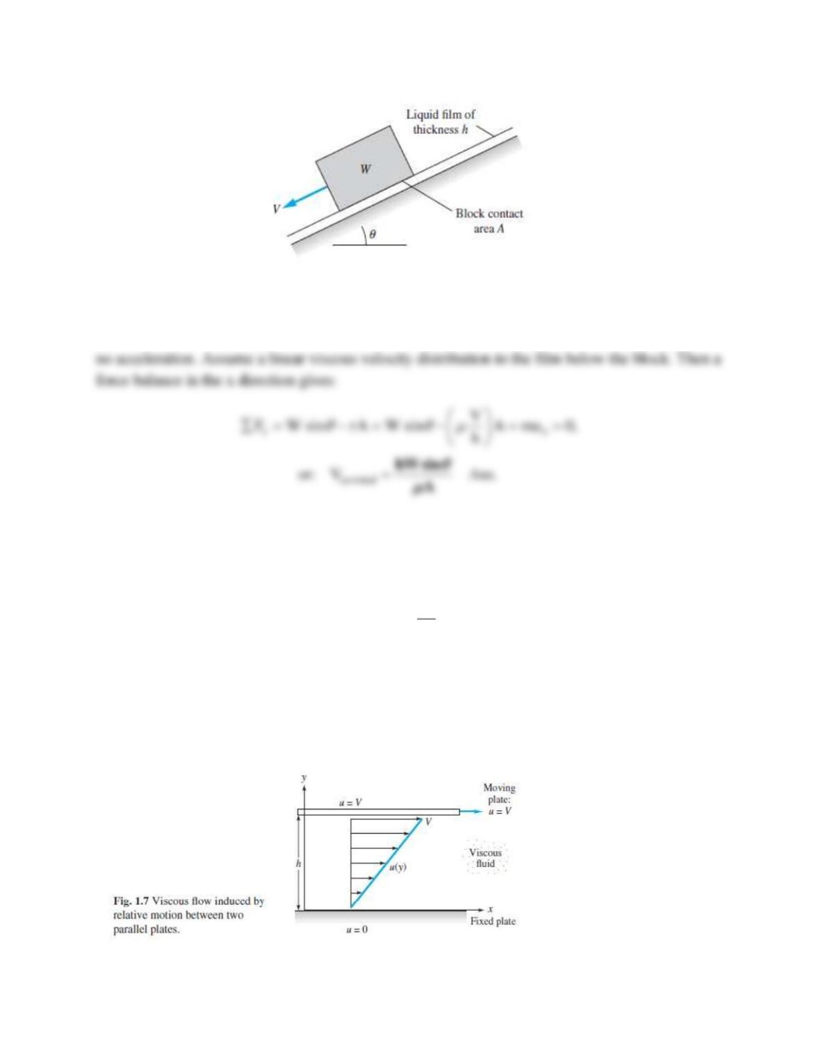
A block of weight W slides down an inclined plane while lubricated by a thin film of oil, as in
Fig. P1.45. The film contact area is A and its thickness is h. Assuming a linear velocity
distribution in the film, derive a “terminal” (zero-acceleration) velocity V of the block.
Find the terminal velocity of the block if the block mass is 6 kg, A = 35 cm2 , θ = 15° , and the
film is 1-mm-thick SAE 30 oil at 20° C.
Figure P1.45
upper timing mark
lower timing mark
capillary tube
Fig. C1.10
The Cannon-
Ubbelohde
bulb of known
reservoir
Solution 1.45
Let “x” be down the incline, in the direction of V. By “terminal” velocity we mean that there is
Problem 1.46
A simple and popular model for two non-newtonian fluids in Fig. 1.8a is the power-law:
where C and n are constants fit to the fluid [16]. From Fig. 1.8a, deduce the values of the
exponent n for which the fluid is (a) newtonian; (b) dilatant; and (c) pseudoplastic. (d) Consider
the specific model constant C = 0.4 N-sn/m2, with the fluid being sheared between two parallel
plates as in Fig. 1.7. If the shear stress in the fluid is 1200 Pa, find the velocity V of the upper
plate for the cases (d) n = 1.0; (e) n = 1.2; and (f) n = 0.8.
()
n
du
Cdy
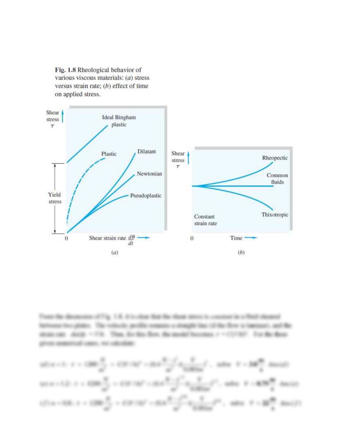
See Figure 1.8 on the next page…
Solution 1.46
By comparing the behavior of the model law with Fig. 1.9a, we see that
(a) Newtonian: n = 1 ; (b) Dilatant: n > 1 ; (c) Pseudoplastic: n < 1 Ans.(a,b,c)
Problem 1.47
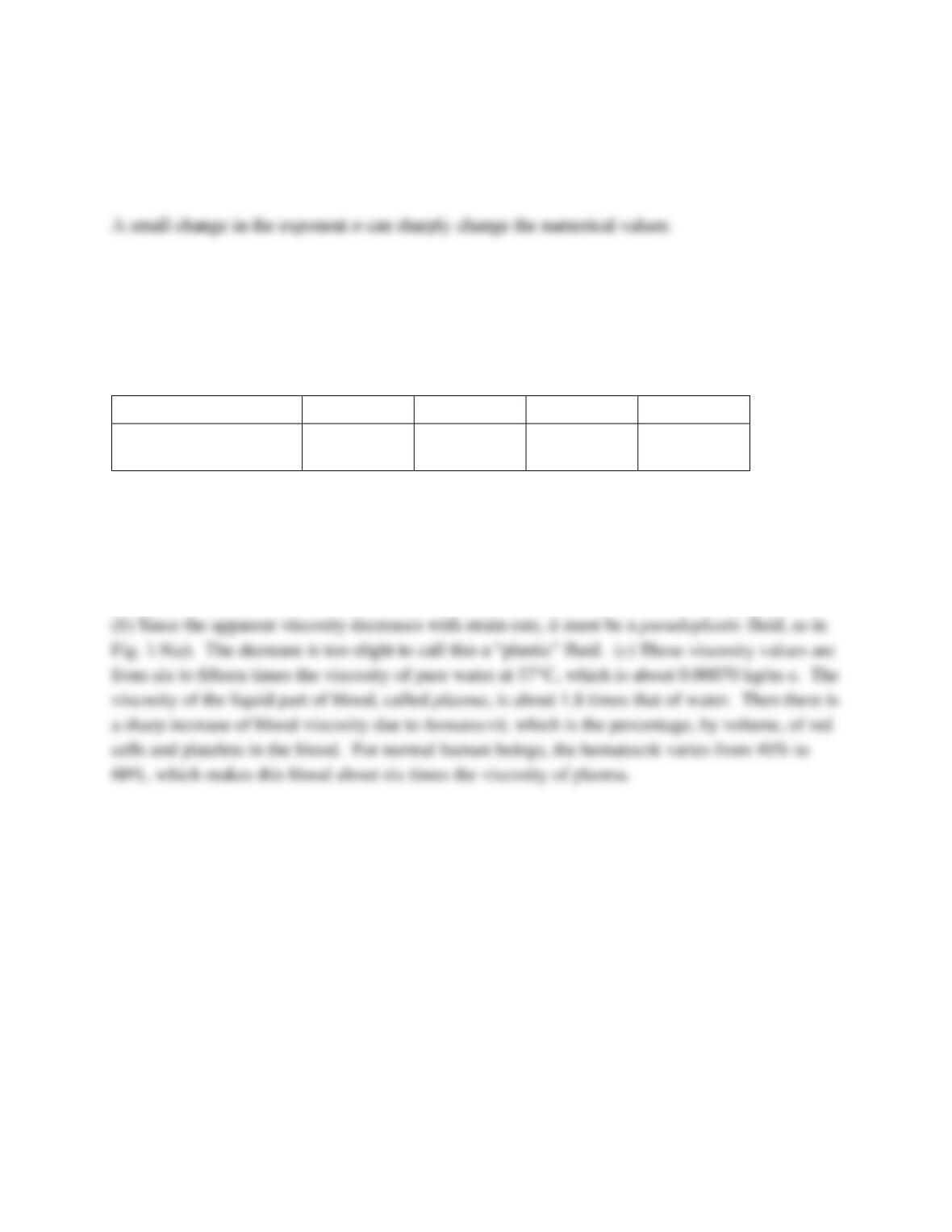
Data for the apparent viscosity of average human blood, at normal body temperature of 37C,
varies with shear strain rate, as shown in the following table.
Shear strain rate, s-1
1
10
100
1000
Apparent viscosity,
kg/(m•s)
0.011
0.009
0.006
0.004
(a) Is blood a non-newtonian fluid? (b) If so, what type of fluid is it? (c) How do these
viscosities compare with plain water at 37C?
Solution 1.47
(a) By definition, since viscosity varies with strain rate, blood is a nonnewtonian fluid.
Problem 1.48
A thin plate is separated from two fixed plates by very viscous liquids μ1 and μ2 , respectively, as
in Fig. P1.48. The plate spacings h1 and h2 are unequal, as shown. The contact area is A between
the center plate and each fluid. ( a ) Assuming a linear velocity distribution in each fluid, derive
the force F required to pull the plate at velocity V . ( b ) Is there a necessary relation between the
two viscosities, μ1 and μ2 ?
Figure P1.48
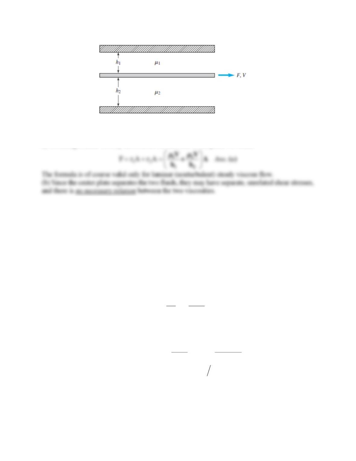
Solution 1.48
a) Assuming a linear velocity distribution on each side of the plate, we obtain
Problem 1.49
An amazing number of commercial and laboratory devices have been developed to measure fluid
viscosity, as described in Ref. 29 and 49. Consider a concentric shaft, fixed axially and rotated
inside the sleeve. Let the inner and outer cylinders have radii ri and ro, respectively, with total
sleeve length L. Let the rotational rate be (rad/s) and the applied torque be M. Using these
parameters, derive a theoretical relation for the viscosity
of the fluid between the cylinders.
Solution 1.49
Assuming a linear velocity distribution in the annular clearance, the shear stress is
i
oi
r
V
r r r
=
−
This stress causes a force dF =
dA =
(ri d
)L on each element of surface area of the inner shaft.
The moment of this force about the shaft axis is dM = ri dF. Put all this together:
23
0
2
ii
i i i
o i o i
r r L
M r dF r r L d
r r r r
= = =
−−
Solve for the viscosity: .Ans
3
() −
ii
r r r L
Problem 1.50
A simple viscometer measures the time t for a solid sphere to fall a distance L through a test fluid
of density
. The fluid viscosity
is then given by
2
3
net
Wt DL
if t
DL
where D is the sphere diameter and Wnet is the sphere net weight in the fluid.
(a) Prove that both of these formulas are dimensionally homogeneous.
(b) Suppose that a 2.5 mm diameter aluminum sphere (density 2700 kg/m3) falls in an oil of density
875 kg/m3. If the time to fall 50 cm is 32 s, estimate the oil viscosity and verify that the inequality is
valid.
Solution 1.50
(a) Test the dimensions of each term in the two equations:
Problem 1.51
An approximation for the boundary-layer shape in Figs. 1.5b and P1.51 is the formula
( ) sin( ) , 0
2
y
u y U y
where U is the stream velocity far from the wall and
is the boundary layer thickness, as in
Fig. P1.51. If the fluid is helium at 20C and 1 atm, and if U = 10.8 m/s and
= 3 mm, use the
formula to (a) estimate the wall shear stress
w in Pa; and (b) find the position in the boundary
layer where
is one-half of
w.
Solution 1.51
From Table A.4, for helium, take R = 2077 m2/(s2-K) and
= 1.97E-5 kg/m-s.
(a) Then the wall shear stress is calculated as
Problem 1.52
The belt in Fig. P1.52 moves at steady velocity V and skims the top of a tank of oil of viscosity
, as shown. Assuming a linear velocity profile, develop a simple formula for the belt-drive
power P required as a function of (h, L, V, b,
). What belt-drive power P, in watts, is required if
the belt moves at 2.5 m/s over SAE 30W oil at 20C, with L = 2 m, b = 60 cm, and h = 3 cm?
Fig. P1.51
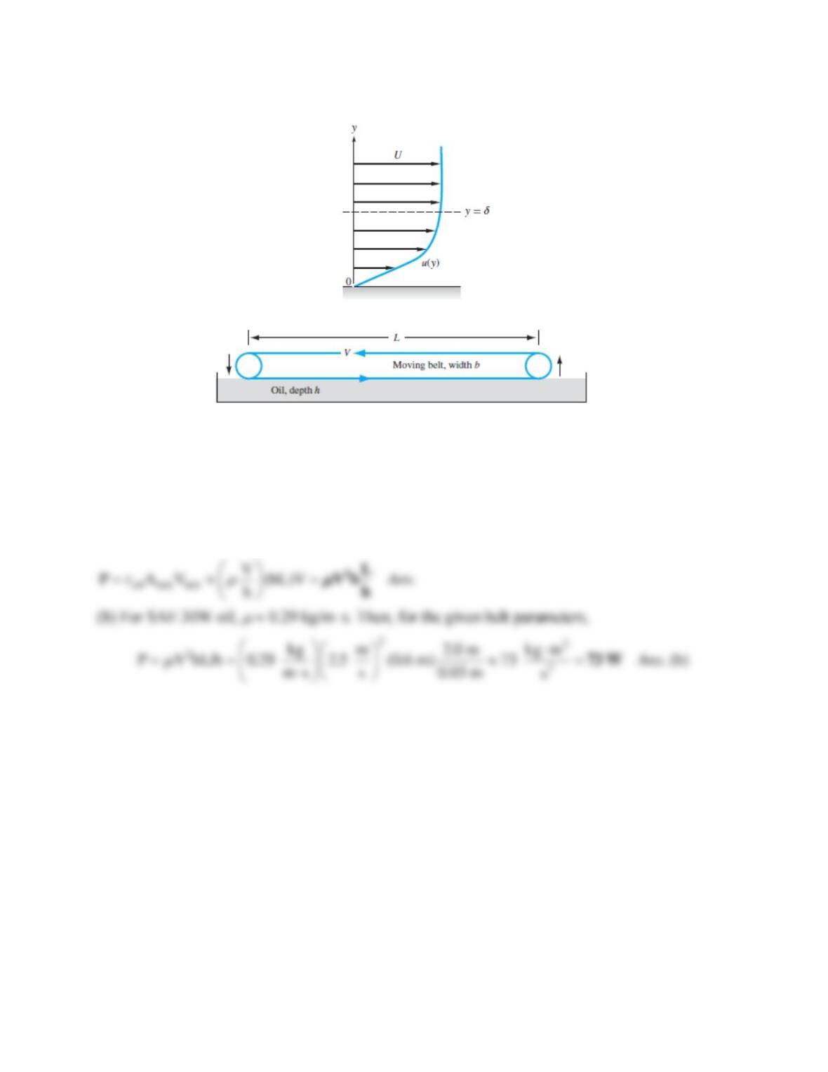
Fig. P1.52
Solution 1.52
The power is the viscous resisting force times the belt velocity:
Problem 1.53*
A solid cone of angle 2θ , base r0 , and density ρc is rotating with initial angular velocity ω0
inside a conical seat, as shown in Fig. P1.53. The clearance h is filled with oil of viscosity μ .
Neglecting air drag, derive an analytical expression for the cone’s angular velocity ω(t) if there is
no applied torque.
Figure P1.53
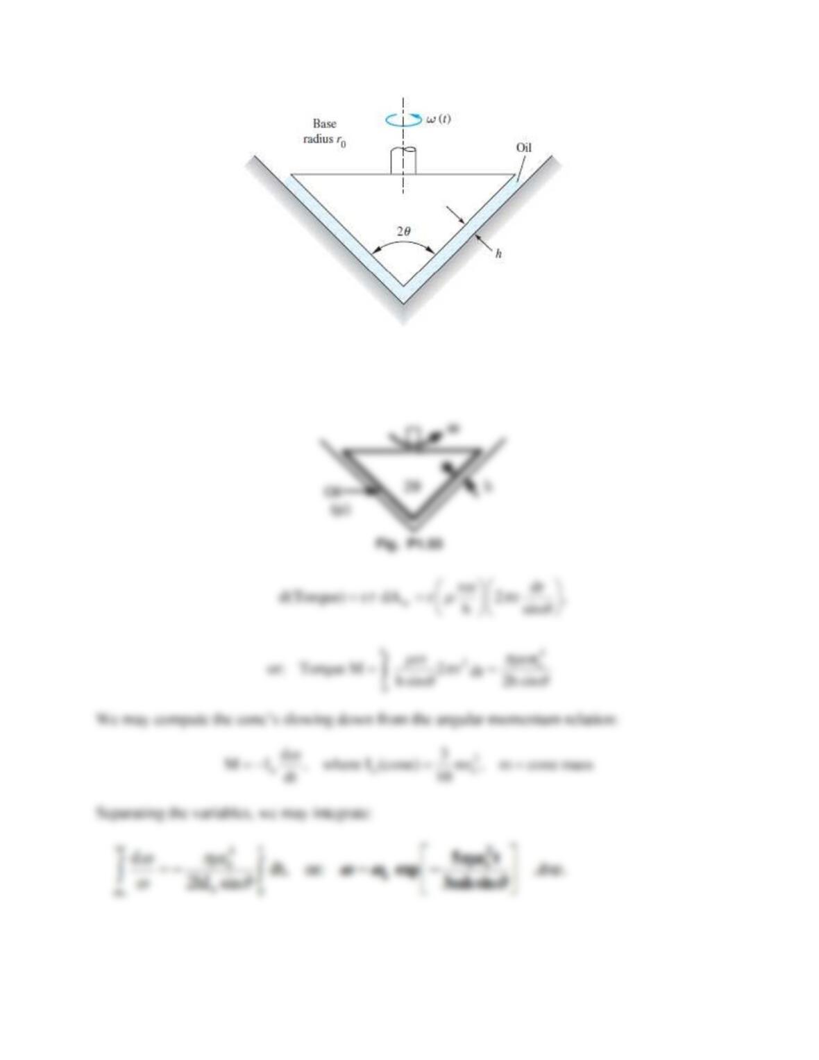
Solution 1.53
At any radial position r ro on the cone surface and instantaneous rate
,
Problem 1.54*
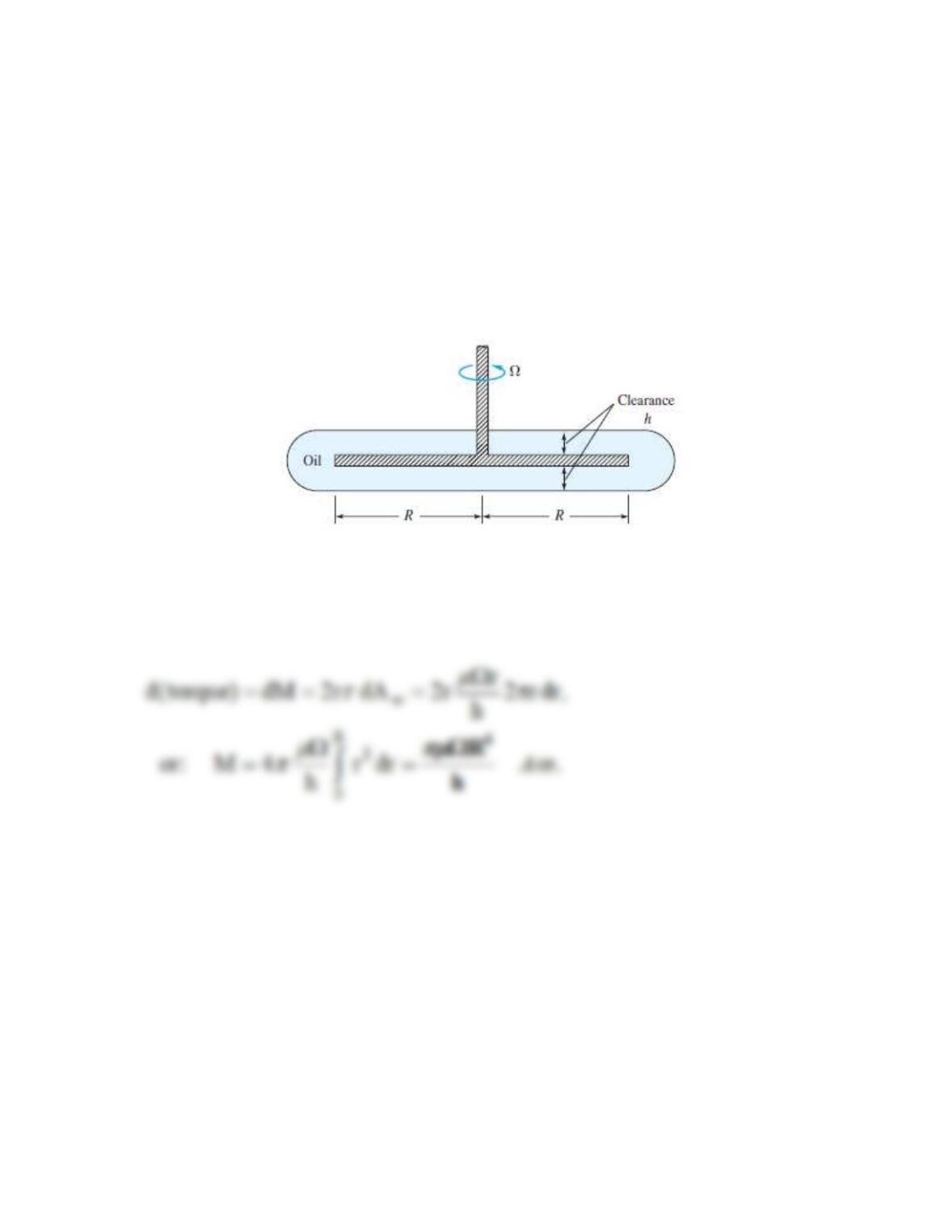
A disk of radius R rotates at an angular velocity Ω inside a disk-shaped container filled with oil
of viscosity μ , as shown in Fig. P1.54. Assuming a linear velocity profile and neglecting shear
stress on the outer disk edges, derive a formula for the viscous torque on the disk.
Fig. P1.54
Solution 1.54*
At any r R, the viscous shear
r/h on both sides of the disk. Thus,
Problem 1.55*
A block of weight W is being pulled over a table by another weight Wo, as shown in
Fig. P1.55. Find an algebraic formula for the steady velocity U of the block if it slides on an
oil film of thickness h and viscosity
. The block bottom area A is in contact with the oil.
Neglect the cord weight and the pulley friction.
Assume a linear velocity profile in the oil film.
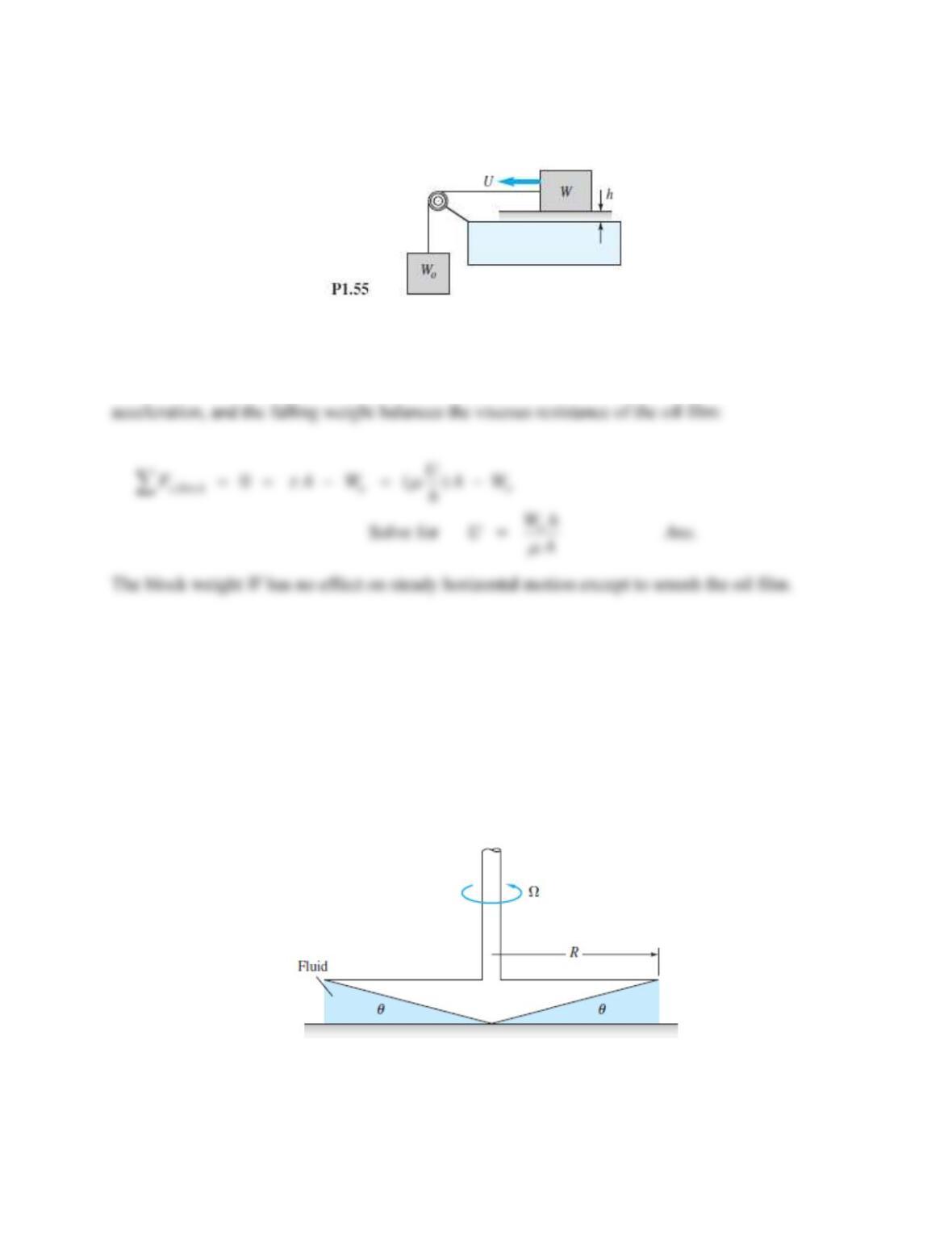
Solution 1.55
This problem is a lot easier to solve than to set up and sketch. For steady motion, there is no
Problem 1.56*
The device in Fig. P1.56 is called a cone-plate viscometer [29]. The angle of the cone is very
small, so that sin θ ≈ θ , and the gap is filled with the test liquid. The torque M to rotate the cone
at a rate Ω is measured. Assuming a linear velocity profile in the fluid film, derive an expression
for fluid viscosity μ as a function of ( M , R , Ω , θ ).
Fig. P1.56
Solution 1.56*
For any radius r R, the liquid gap is h = r tan
. Then
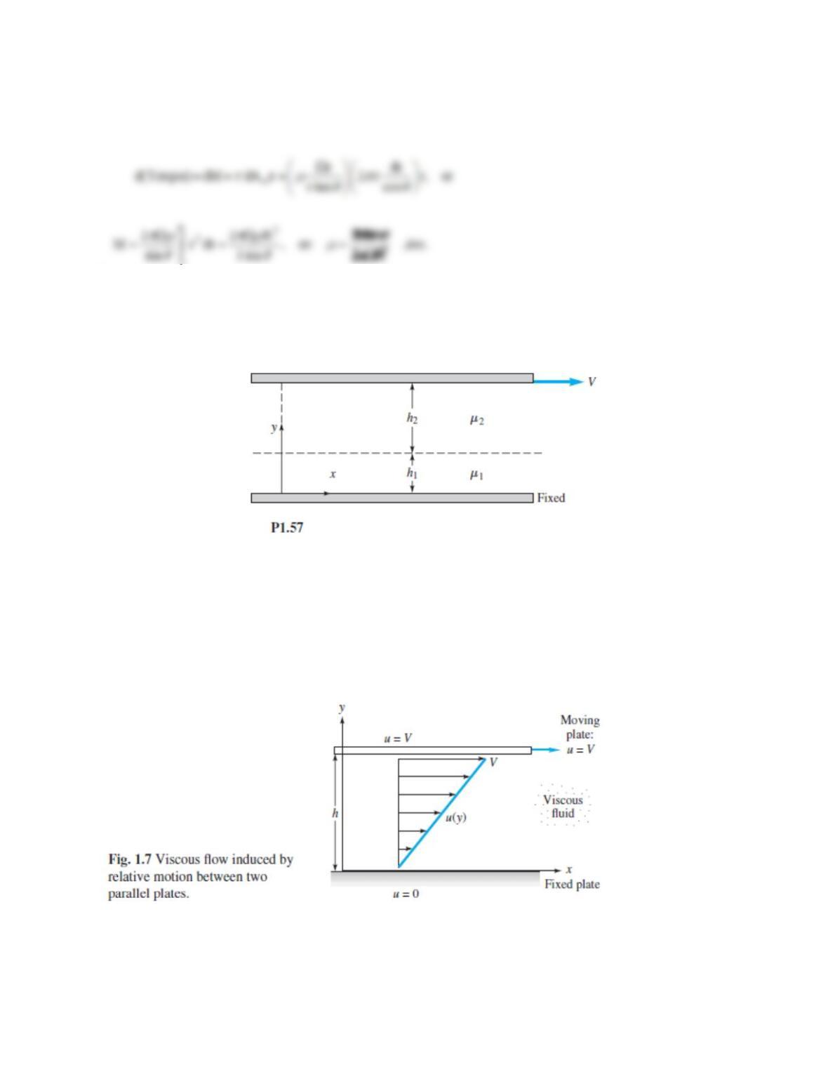
Problem 1.57
Extend the steady flow between a fixed lower plate and a moving upper plate,
from Fig. 1.7, to the case of two immiscible liquids between the plates, as in Fig. P1.57.
(a) Sketch the expected no-slip velocity distribution u(y) between the plates. (b) Find an analytic
expression for the velocity U at the interface between the two liquid layers. (c) What is the result
of (b) if the viscosities and layer thicknesses are equal?
Solution 1.57
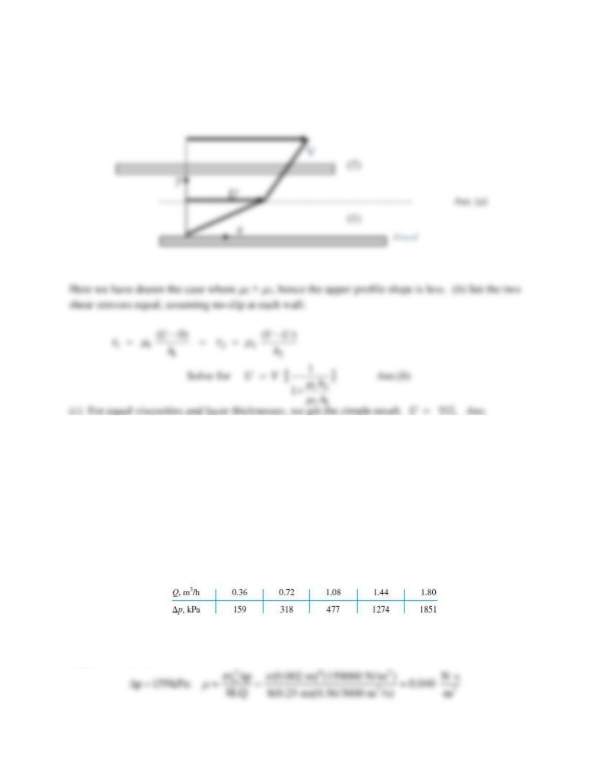
We begin with the hint, from Fig. 1.8, that the shear stress is constant between the two plates.
The velocity profile would be a straight line in each layer, with different slopes:
Problem 1.58*
The laminar pipe flow example of Prob. 1.12 can be used to design a capillary viscometer [29].
If Q is the volume flow rate, L is the pipe length, and Δp is the pressure drop from entrance to
exit, the theory of Chap. 6 yields a formula for viscosity:
=
ro4p/(8LQ).
Pipe end effects are neglected [29]. Suppose our capillary has r0 = 2 mm and L = 25 cm. The
following flow rate and pressure drop data are obtained for a certain fluid:
Solution 1.58
Apply our formula, with consistent units, to the first data point:
Problem 1.59
A solid cylinder of diameter D, length L, density
s falls due to gravity inside a tube of diameter Do.
The clearance,
o
(D D) D,
−
is filled with a film of viscous fluid (
,
).
Derive a formula for terminal fall velocity and apply to SAE 30 oil at 20C for a steel cylinder with
D = 2 cm, Do = 2.04 cm, and L = 15 cm. Neglect the effect of any air in the tube.
Solution 1.59
The geometry is similar to Prob. 1.47, only vertical instead of horizontal. At terminal velocity,
the cylinder weight should equal the viscous drag:
Problem 1.60
Pipelines are cleaned by pushing through them a close-fitting cylinder called a pig. The name comes
from the squealing noise it makes sliding along. Ref. 50 describes a new non-toxic pig, driven by
compressed air, for cleaning cosmetic and beverage pipes. Suppose the pig diameter is 5-15/16 in and
its length 26 in. It cleans a 6-in-diameter pipe at a speed of 1.2 m/s. If the clearance is filled with
glycerin at 20C, what pressure difference, in pascals, is needed to drive the pig? Assume a linear
velocity profile in the oil and neglect air drag.
Solution 1.60
Since the problem calls for pascals, convert everything to SI units:
Find the shear stress in the oil, multiply that by the cylinder wall area to get the required force,
and divide the force by the area of the cylinder face to find the required pressure difference.
Problem 1.61*
An air-hockey puck has a mass of 50 g and is 9 cm in diameter. When placed on the air table, a
20°C air film, of 0.12-mm thickness, forms under the puck. The puck is struck with an initial
velocity of 10 m/s. Assuming a linear velocity distribution in the air film, how long will it take
the puck to ( a ) slow down to 1 m/s and ( b ) stop completely? Also, ( c ) how far along this
extremely long table will the puck have traveled for condition ( a )?
Solution 1.61
For air at 20C take
1.8E−5 kg/m·s. Let A be the bottom area of the puck, A =
D2/4.