Solution 3.7
See example 3.5 for hand calculations. I solved this using UniSim ExchangerNet R360 and got the following
olution 3.8
S
.5 for hand calculations. I solved this using UniSim ExchangerNet R360 and got the following
See example 3
answers:
21
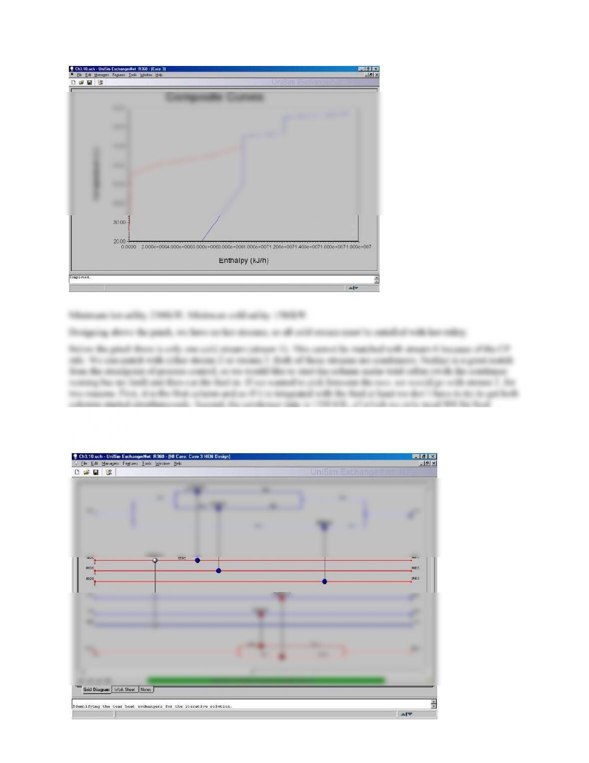
preheat, so we will have at least 450 kW of utility cooler that can be used to get the column started up. The resulting
network is shown below:
22
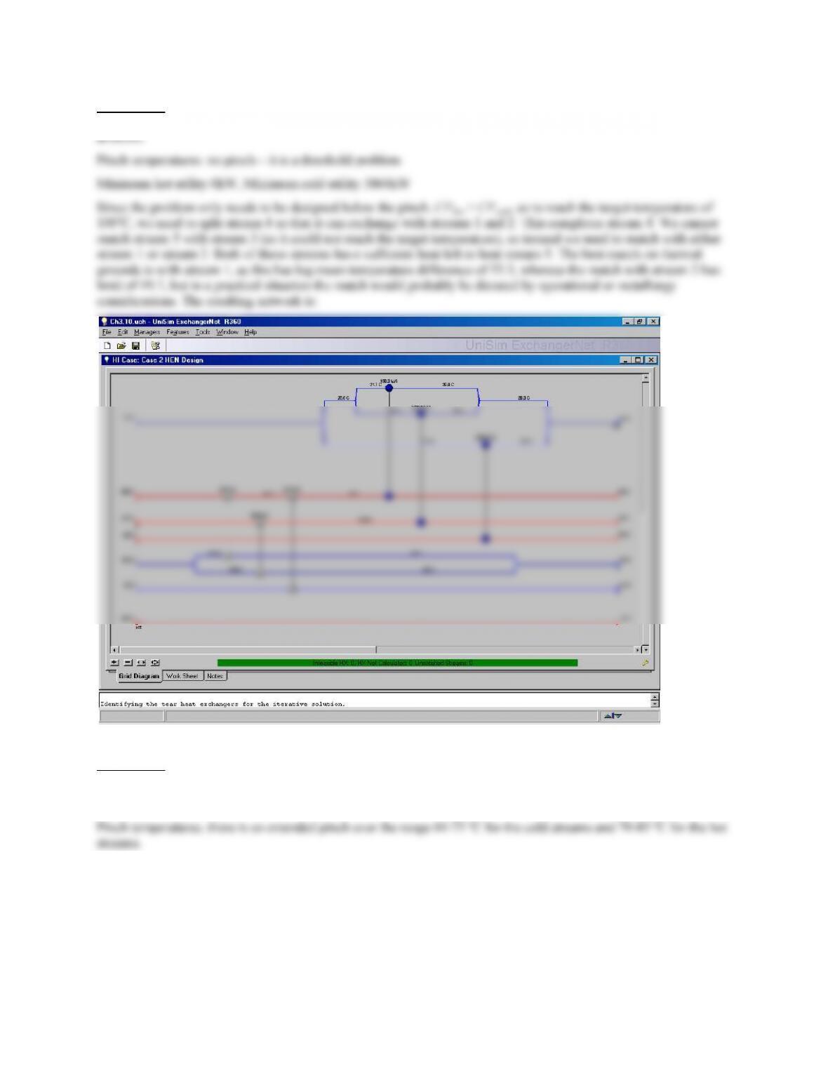
Solution 3.9
I solved this using UniSim ExchangerNet R360 and got the following answers:
Temperature difference to become a threshold problem = 10 ºC
With this temperature approach we have a pinch at 30 ºC (cold stream temperature) and a near-pinch at 80 ºC (cold
stream temperature). Over the temperature range below 80 ºC there is only one cold stream available (stream 3), and
so this stream must be split to accommodate both hot streams. We also need to use an additional cooler between
streams 1 and 3 to reach the target temperature for stream 1.
Above 80 ºC (cold stream temperature) we can use the same design used in example 3.6. This gives the network:
23

24
Chapter 4
The problems in this chapter all involve flowsheeting. Some can be solved with hand calculations, but most of the
problems are most easily solved using a process simulation program. Because of differences between the simulation
programs and the models that they use, different answers may be obtained depending on the software that is used.
In order to make the answers as generic as possible, several of the solutions are given in outline form, i.e., a
description of the steps that should be followed, rather than full worked solutions. Students should be encouraged to
submit screen shots or converged simulation files (where appropriate) to demonstrate that they have solved the
problem.
Solution 4.1
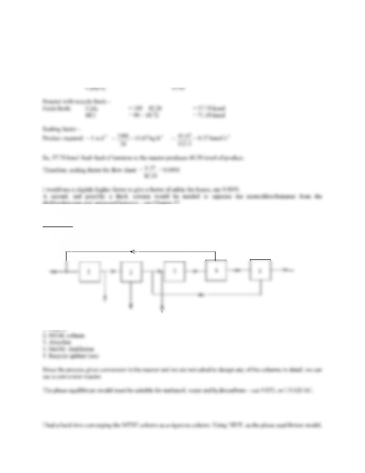
Basis 100 kmol benzene at reactor inlet
Reactor:
Absorber:
HCl In = (70.90)(36.5) = 2588 kg
HCl dissolved = (2588)(0.9999) = 2588 kg
2588 = 8626 kg
Distillation:
Feed: C6H6 44.48 kmol
25
Overheads:
With 0.95% recovery, C6H6 = (44.48)(0.95) = 42.26 kmol
Bottoms: C6H6 = 44.48 – 42.26 2.22 kmol
C6H5Cl 40.50
dichlorobenzene and unreacted benzene – see Chapter 17.
Solution 4.2
1. Reactor
The methanol feed to the reactor is 10% excess of stoichiometric, i.e. 1.1 × 0.49 = 0.539 times the molar feed rate.
This ratio can be maintained using a controller (I used a “set” function in UniSim)
26
Solution 4.3
What follows is a partial solution and notes. This problem can be solved by hand calculations or using a process
simulator (or by a combination of both).
water in feed = 57.56 × 103 ×
125.0
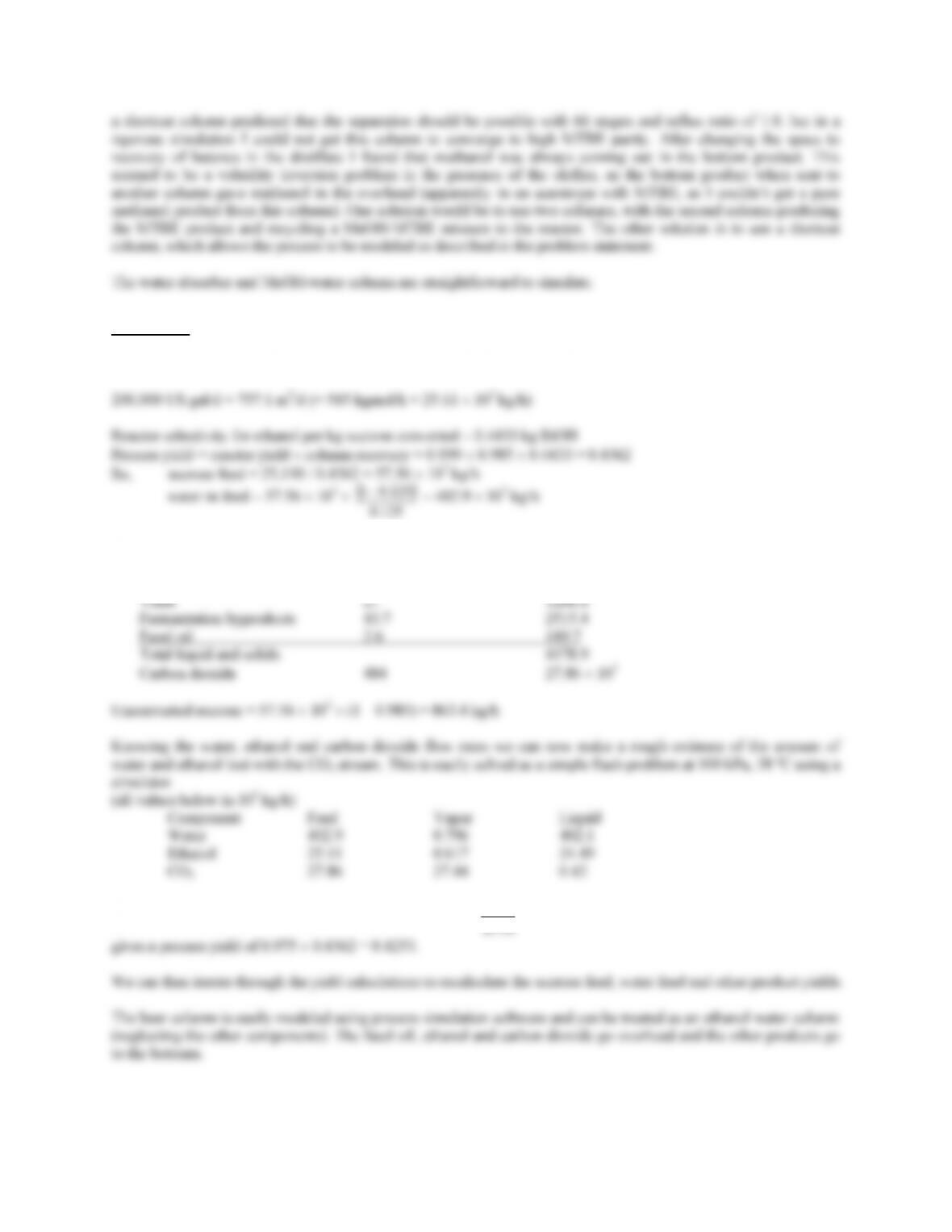
Knowing the sucrose feed and the yield structure we can write down the net yield of all other products:
Product Yield g/kg sucrose Production rate (kg/h)
Non-sugar solids 5.3 305.0
So the reactor yield should also be reduced by a factor 1 –
11.25
617.0 = 0.975 to allow for EtOH loss with the CO2. This
27
Solution 4.4
200,000 US gal/d of EtOH = 757.1 m3/d (= 545 kgmol/h = 25.11 × 10³ kg/h)
Solution 4.5
200,000 US gal/d of EtOH = 757.1 m3/d (= 545 kgmol/h = 25.11 × 10³ kg/h)
Solution 4.6
This problem can be solved by hand calculations using the information given, or using a process simulator.
Basis: 100 kmol/h of Cl2
28
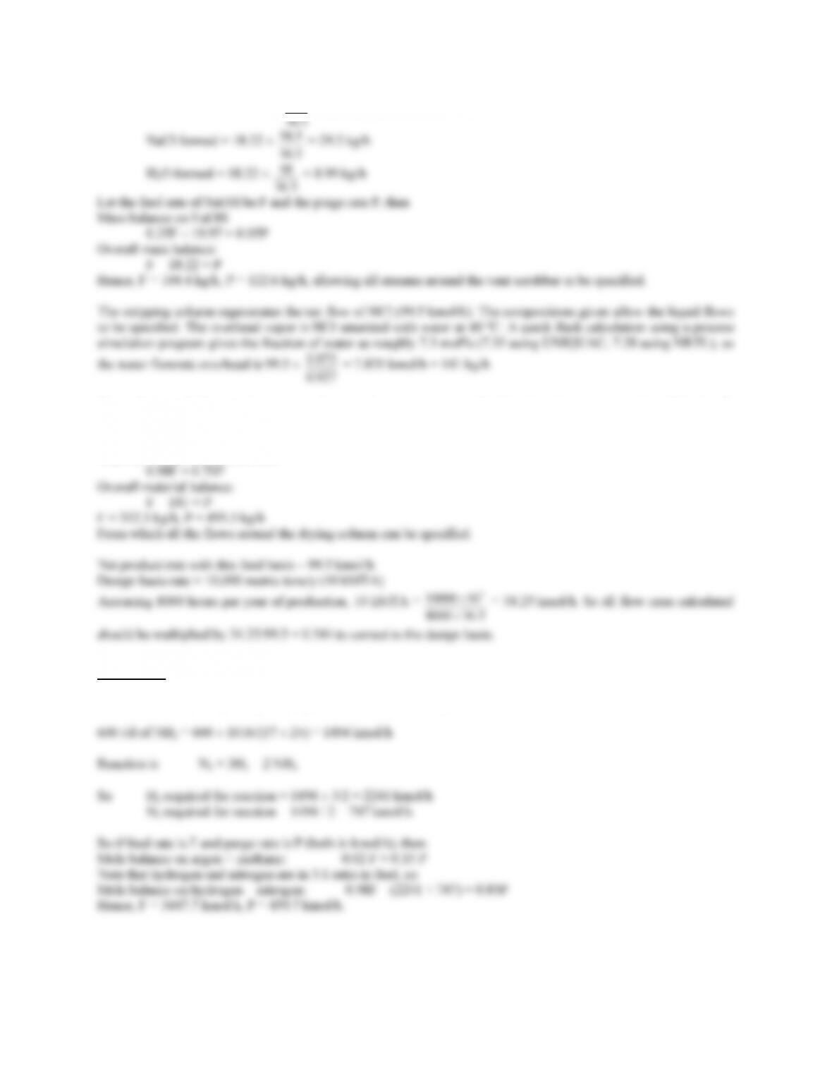
NaOH reacted = 18.22 ×
40 = 19.97 kg/h
5.58 = 29.2 kg/h
The sulfuric acid drying column is another recycle-purge system, only this time there is no reaction. If feed = F,
purge = P,
Material balance on sulfuric acid:
Solution 4.7
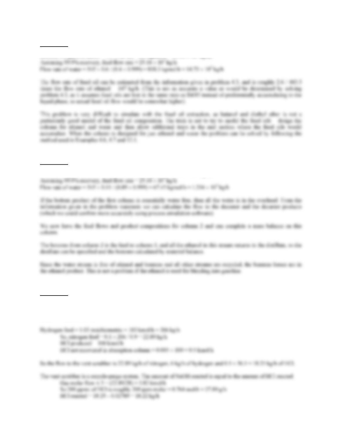
This is a relatively simple recycle-purge calculation and is easily solved by hand.
With the flow rates of feed and purge, all the stream flows can be specified.
The purge stream should be taken after the ammonia has been condensed, so as to minimize losses of ammonia. A
29

99615.0
nitrogen should be increased by a ratio 1495.7/1494 = 0.11%.
Solution 4.8
This problem should be solved using a process simulation program. This is a very difficult problem, requiring
simulation of several operations that involve liquid-liquid equilibrium.
met).
The TCE extraction is solved in problem 17.9. It is hard to set up in a simulator unless the phase equilibrium model
is matched to the data. (Using the UNIFAC values in UniSim I found too much water in the TCE phase using
Solution 4.9
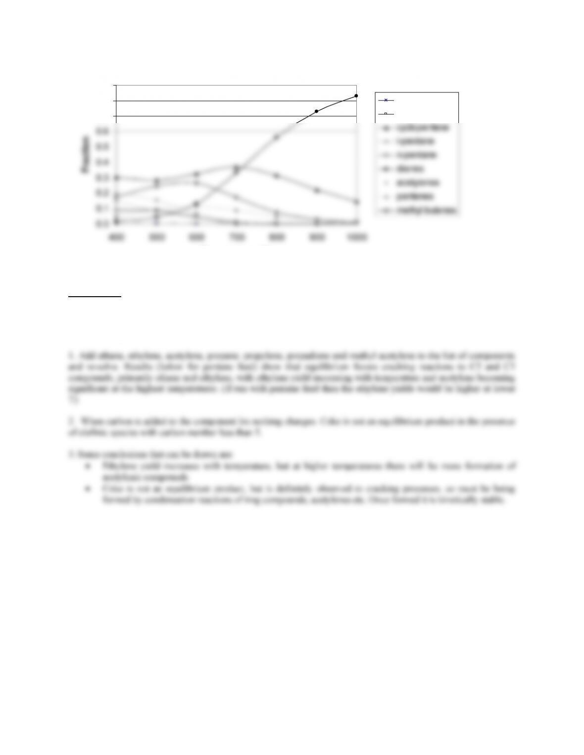
This problem is an exact repeat of Example 4.4, using a different feed molecule. Select any of the mono-olefinic
species as feed, as they all have empirical formula C5H10.
30
0.0
0.7
0.8
0.9
Temperature (C)
22Mpropane
cyclopentane
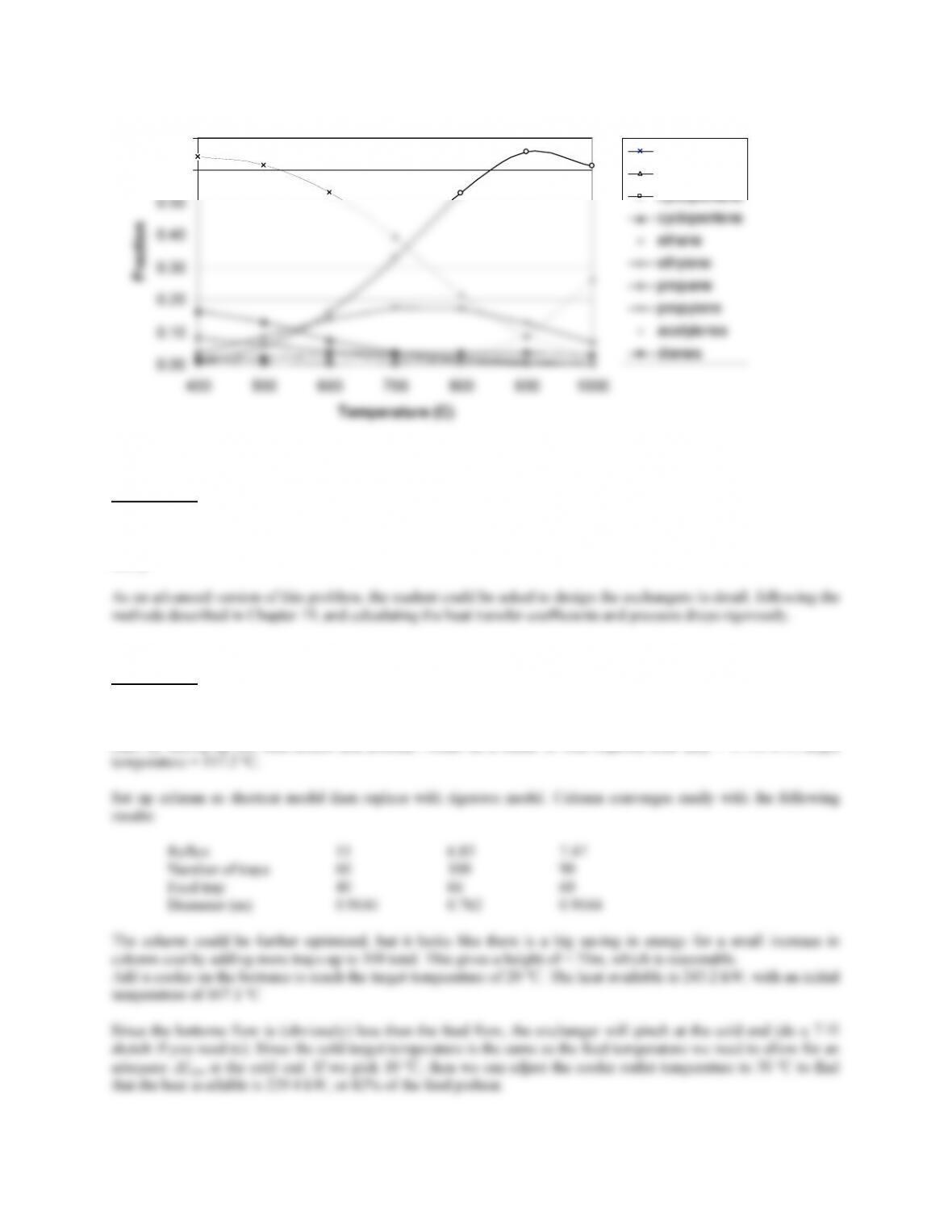
Solution 4.10
This problem requires repeating Example 4.4 using different sets of components in the feed and products. Since we
are interested in equilibrium distributions, a Gibbs reactor can be used. The following results were generated using
UniSim Design.
31
0.00
0.50
0.60
0.70
400 500 600 700 800 900 1000
Temperature (C)
pentanes
pentenes
cyclopentane
Solution 4.11
This is a straightforward repeat of Example 4.8. The optimal value found for total heat transfer area depends on the
values assumed for heat transfer coefficients in each of the exchangers and the temperatures assumed for the hot
utility.
Solution 4.12
This problem should be solved using process simulation software. The following solution used UniSim Design.
Start by setting up the feed stream and preheat. Model as a heater to find required total duty = 279.6 kW, target
32
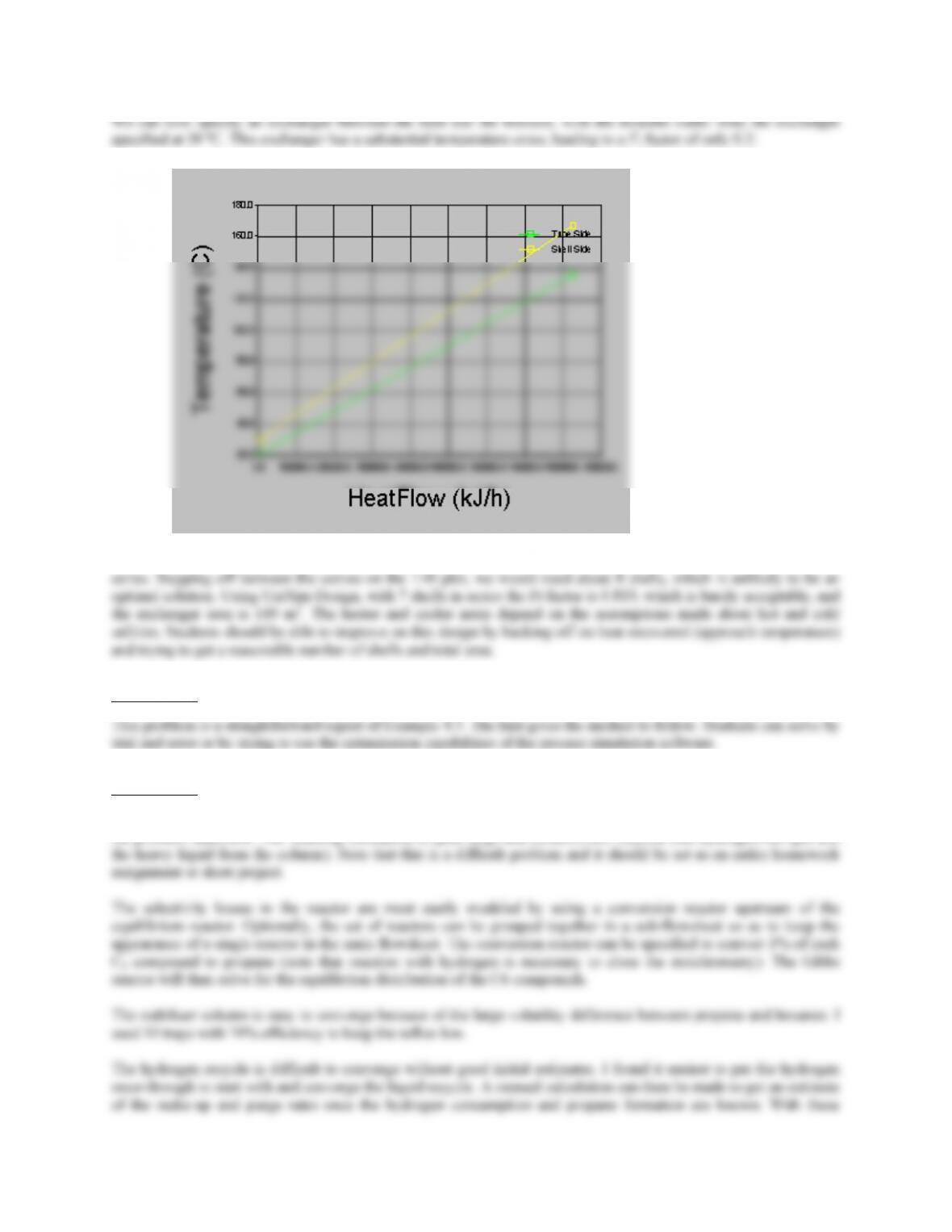
We could resolve this by recovering less heat (probably the optimal solution) or using a large number of shells in
Solution 4.13
Solution 4.14
This problem requires modifying the simulation developed in Example 4.10 with the additional details specified in
the problem statement. The resulting simulation is quite large and contains two recycles (the hydrogen-rich gas and
33
Solution 4.15
Use Figure 4.2 as an aid to selecting a suitable method.
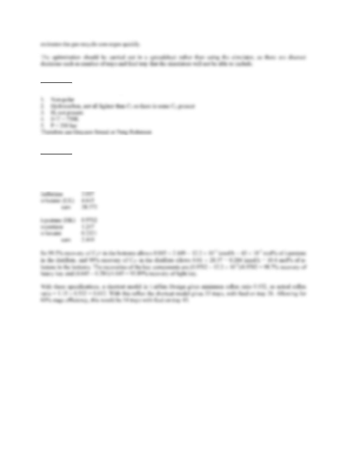
Solution 4.16
This is a straightforward column simulation problem. I used UniSim design. Light key is n-butane and heavy key is
isopentane.
Molar flows (kmol/h) are:
Propane 20.63
34
35

Solution 4.17
36
Chapter 5
Solution 5.1
a) A fermenter is a well-mixed vessel, regardless of whether it is run in continuous or batch mode. A
thermocouple in a thermowell will be adequate. Care should be taken to ensure that the thermowell is not
Solution 5.2
a) The vaporizer control scheme relies on using the level controller to maintain a constant liquid inventory by
A low level in the vessel would signal that the feed rate had become too low relative to the heating rate.
This could be because system back pressure had been lost (causing rapid flashing of the liquid), steam flow
rate was too high due to failure of the steam valve or steam trap, liquid could be leaking from the vessel
b) The high and low level alarms should activate a shutdown trip that would close isolation valves on the feed
37
Solution 5.3
Notes on a possible control scheme:
1. Each reactor requires a level controller on the outlet liquid to maintain inventory.
2. Each heat exchanger requires a temperature measurement on the outlet stream, actuating a flow controller
on the tube-side utility stream.
Solution 5.4
a) This is a very common fermenter control arrangement. See Section 15.9.7 for a discussion of the variables
Solution 5.5
Notes on a possible control scheme:
1. Close control of the reactor temperature is important. If control is lost the reactor seals could be blown and
carcinogenic compounds released into the atmosphere. Interlocks and alarms should be included in the

Solution 5.6
Notes on a possible control scheme:
1. The feed is from storage, so a flow controller should be installed to main constant flow to the column. A
recorder could be included to give a record of the quantity of feed processed.
4. The primary control of quality would be achieved by controlling the reflux rate to meet the product purity
specified. Temperature control could be used but the sensing point would need to be sited at a point in the
39
Chapter 6
Solution 6.1
Solution 6.2
1. Carbon steel, schedule 40, life 3 years
Number of replacements = 3
Therefore, the best choice is stainless steel.
Solutions 6.3, 6.4, 6.5, 6.6 and 6.7
Solution 6.8
Solution 6.9
See Section 6.4.7.
1. Coal addition system must handle flow of abrasive solids at low temperatures. Carbon steel could be used
with suitable inspection and replacement schedule.
40