
Solutions to Towler & Sinnott Chemical Engineering Design 2nd edition
Part I: Process Design Part II Plant Design
Chapter 1: Introduction Chapter 13: Equipment design
Chapter 2: Flowsheet development Chapter 14: Pressure vessel design
Chapter 3: Utilities and energy recovery Chapter 15: Reactor design
Chapter 4: Process simulation Chapter 16: Separation processes
Chapter 5: Process control Chapter 17: Multistage columns
Chapter 6: Materials of construction Chapter 18: Solids handling processes
Chapter 7: Estimating capital costs Chapter 19: Heat transfer equipment
Chapter 8: Estimating costs of production Chapter 20: Plant hydraulics
Chapter 9: Economic analysis
Chapter 10: Safety
Chapter 11: Plant layout and environmental impact
Chapter 12: Optimization
Note that most of the problems involve design and so have no single unique answer. Credit should be
given to students who have followed the right method and found similar solutions. Indeed, the
probability of any student independently coming up with the exact answers given in the solution set for
more than a few problems should be vanishingly small and this event should cause the grader to be
suspicious. The “optimal” solutions presented are usually not numerically optimal and are merely close
enough to optimal to be good enough for engineering purposes. This reflects the optimization
philosophy described in Chapter 12.
When teaching design, I usually do not give the teaching assistants prepared solutions to the homework
problems. I find that if they have to work through the problems themselves they are much better
prepared to help the students. They are usually not too happy about it, but it does them good and builds
character.
1
Chapter 1
Problem 1.1
There are many possible correct answers to this question and it can be answered in varying levels of
detail. The key steps that should be included for each process with typical required times are listed
below. The project plan can be sketched using a spreadsheet or drawn up using a project planning tool
such as MS Project (as in Problem 1.2).
a) A petrochemical process using established technology, to be built on an existing site. Since the
technology is established, there will be no need to generate design concepts and carry out R&D.
The steps are then:
b) A process for full-scale manufacture of a new drug, based on a process currently undergoing pilot
plant trials. Since the pilot plant is already operating the designer already has a good idea of the
process flowsheet and the goal is to be prepared to ramp up production to full scale once the drug
is approved. The steps are:
c) A novel process to convert cellulosic waste to fuel. The technology and flowsheet will need
considerable development, so a schedule might be:
d) A spent nuclear fuel reprocessing facility. There is established technology for nuclear fuel
e) A solvent recovery system for electronics production. This is a relatively small project, so the steps
would be:
2
Problem 1.2
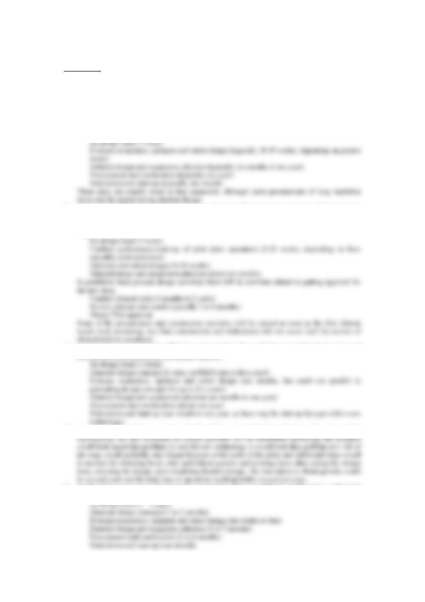
This requires a more detailed breakdown than problem 1.1. A sample project plan is given in the
lecture slides and shown below (in MS Project format):
Problem 1.3
a) The list of product requirements will be somewhat qualitative and depend on the preferences
of the “customer” group. The required properties of the dough must consider properties of the
dough itself, as well as properties of the final (home-baked) product. Some properties of the
dough that might be considered include:
b) The product specifications could include the following:
• Composition of major ingredients (see any cookie dough: flour, fat or oil, water, etc.)
• Composition of chocolate chips
3

4

Chapter 2
Solution 2.1
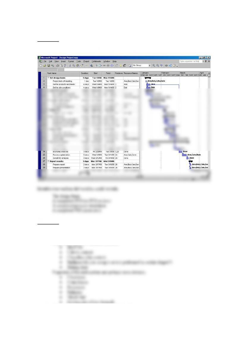
This process can be drawn in more detail, but a simple block-flow diagram is adequate. There may be a need for some heaters and coolers in the plant (e.g. after
neutralization), but these are not described in the problem statement and would not need to be shown in a block-flow diagram. Since the process involves batch distillation, it
would also be possible to operate the reactor in batch mode and then carry out the neutralization and wash stages in batch mode in the same vessel.
Reactor Neutralizer Water Wash Batch Still Vacuum Still
Light ends
6
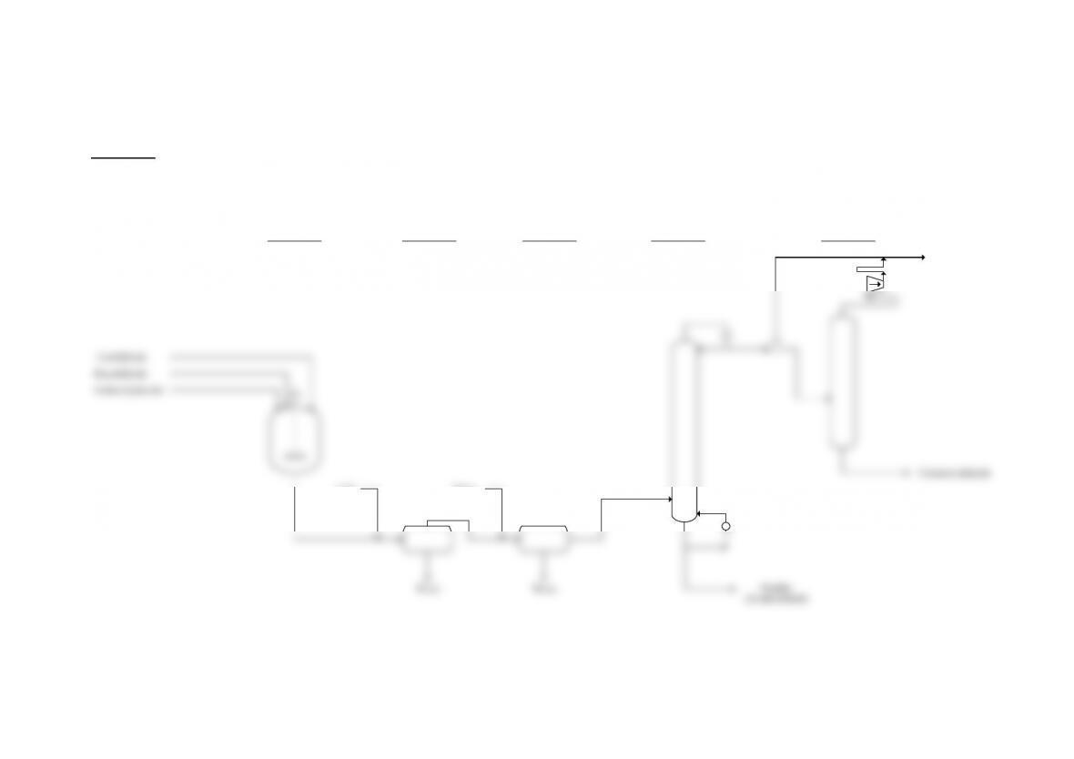
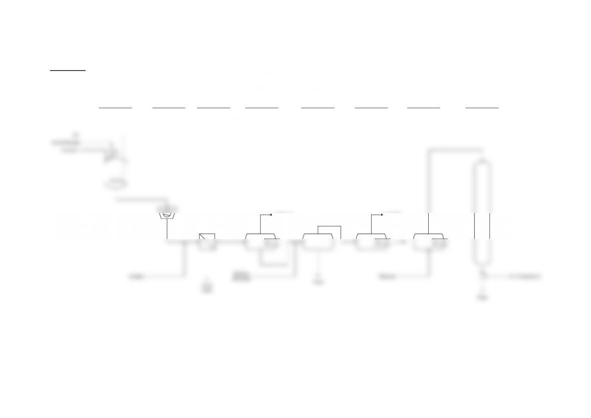
Solution 2.2
This is a continuous process and has a more complex flowsheet incorporating two recycles:
Lights
Column
Heavies
Column
Alkylation
Reactor
Benzene
Column
Cumene
Column
Transalkylation
Reactor
Cooler
Benzene
7
8
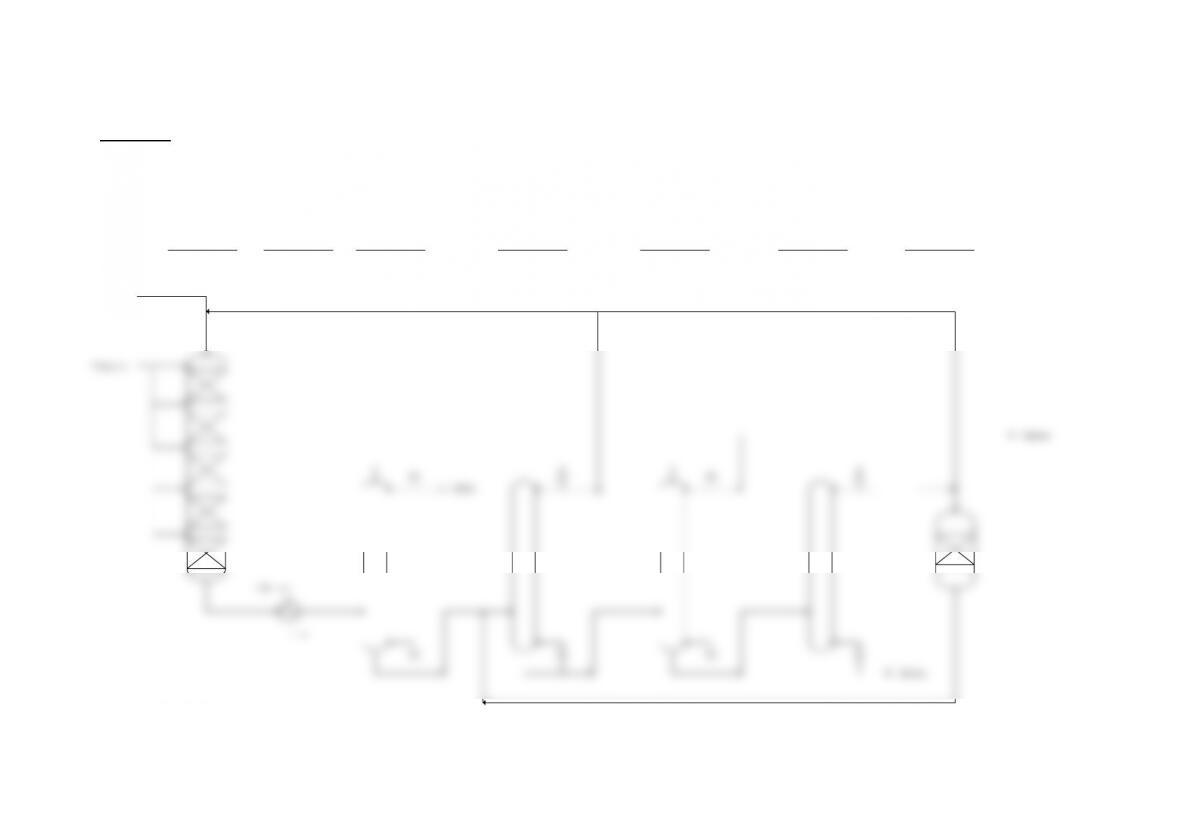
Solution 2.3
This is also a batch process in which some of the extraction steps could be carried out reusing the same equipment. The dashed line shows the reuse of the EDC evaporator to
dissolve the product in MeOH for chromatography.
Inoculum
Methanol
Dichloride Waste
Waste
Solids
Ethylene
Dichloride
Waste
Chromatography
Column
EDC
Evaporator
EDC
Evaporator
Extractor
MeOH
Evaporator
FilterJet MillFermenter(s)
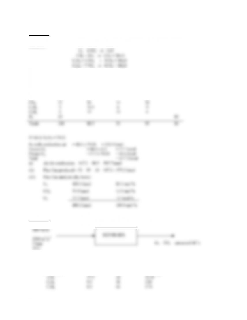
Solution 2.4
Basis for calculation: 100 kmol dry gas
Reactions: CO + 0.5O2 → CO2
REACTANTS PRODUCTS
Syn. Gas O
2 CO2 H
2O N2
CO2 4 4
CO 16 8 16
H2 50 25 50
Solution 2.5
35oC
At low pressures vol% = mol%
(i) Basis: 1 kmol of off-gas
Component mol% MW mass (kg)
9
(iii) Basis: 100 kmol of feed
Reaction (1): CnH2n+2 + n(H2O) → n(CO) + (2n + 1)H2
Component n Amount CO H2
CH4 1 77.5 77.5 232.5
C2H6 2 9.5 19.0 47.5
⎠
⎝
100
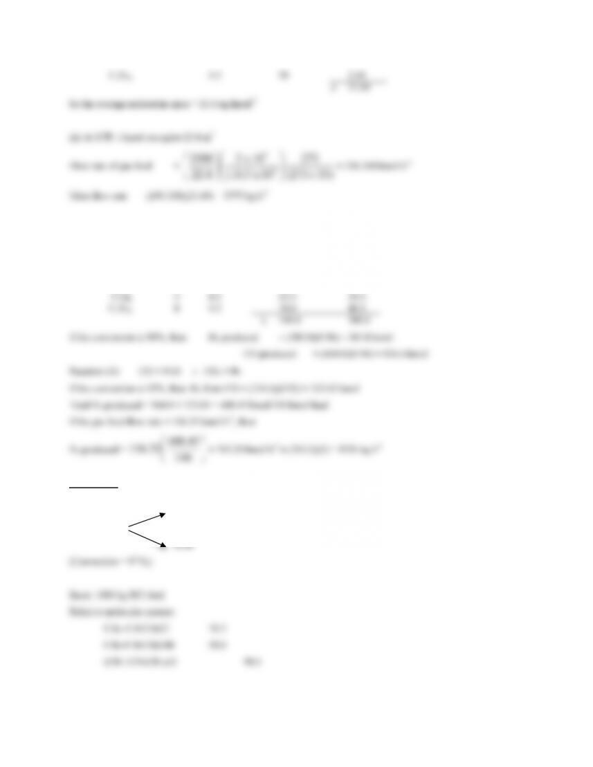
Solution 2.6
ROH (Selectivity = 90 %)
RCl
10
1000 = 13.072 kmol
Solution 2.7
Basis: 100 kmol nitrobenzene feed.
(a, b)
The conversion of nitrobenzene is 96% and so 100(1 – 0.96) = 4 kmol are unreacted.
Inerts in the feed at 0.005 mol fraction (0.5%) = 005.01
005.0
)95.04.302(
−
+x
11
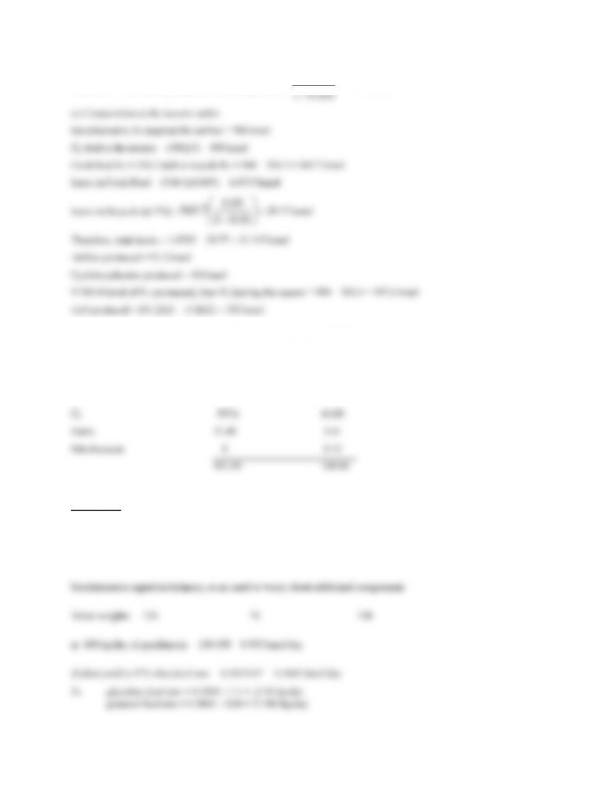
Therefore: Total fresh hydrogen feed including inerts = 005.01
3.334
−
= 336.0 kmol
Composition: kmol mol %
Aniline 91.2 9.90
Cyclo-hexalymine 4.8 0.52
H2O 192 20.85
Solution 2.8
Start by looking at the reaction stoichiometry:
C
7H8O2 + C3H6O2 = C10H14O4
12
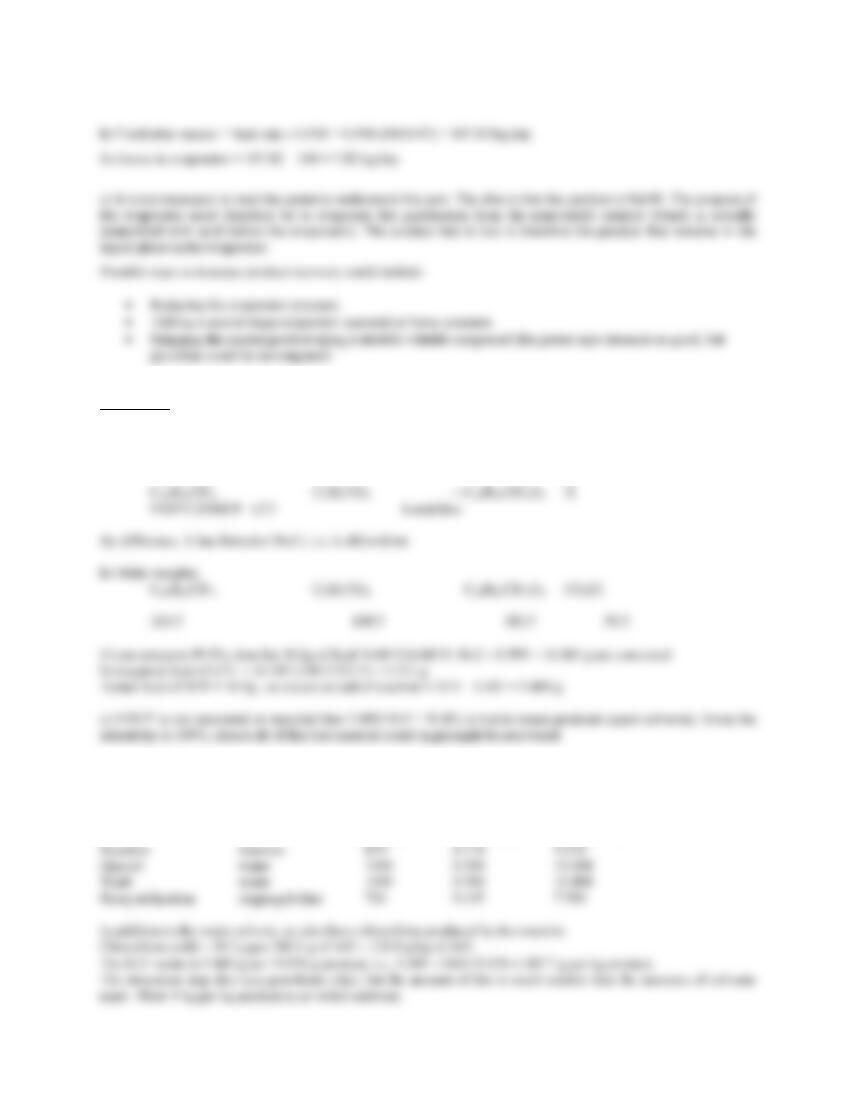
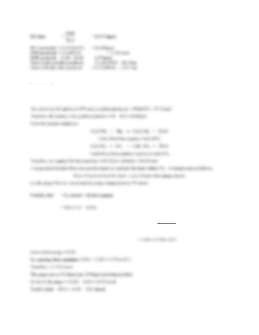
Solution 2.9
It is not necessary to read the patent to answer this question.
a) Start by writing a stoichiometric equation:
d) The feed of 16.2 g of NMP-CDHBCP gives a yield of 16.2 × 0.999 × (382.5/324.5) = 19.076 g of product, so per
kg of API we require 200 ml × 1000/19.076 = 10.484 liters of each solvent at each step.
Step solvent density mass mass
(kg/m3) (kg/200ml) (kg/kg API)
13
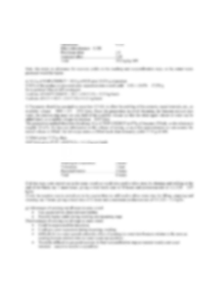
So total mass of waste produced is:
Water 20.968
Benzene 9.216
Reaction time is 18 hours. Estimated times for the other processing steps might be:
Cooling & quench: 2 hours
Decanting 1 hour
14
Solution 2.10
The descriptions below were based on the Kirk Othmer encyclopedia entries. More detail could be added, but the
summaries below are adequate to sketch a block flow diagram of the process.
a) Phosphoric acid
Most phosphoric acid is made by the wet process and is then used for making fertilizers. In the wet process,
for cooling. The reactor product is sent to crystallizers for adipic acid recovery. The crystals are washed, then
redissolved in hot water and recrystallized to purify the adipic acid.
c) Polyethylene terephthalate
PET is a polyester, formed by condensation polymerization of ethylene glycol (EG) and terephthalic acid (TA).
Solution 2.11
To begin we need to calculate the temperatures that can be handled by the heater and cooler in the revamped case.
Starting with the steam heater, E102:
New overall heat transfer coefficient = 513 W/m2K (from the example)
15
For the plate heat exchanger E101, we now have:
Duty Q101 = 1.5 × 104 × (128.8 – 40) = 1.33 MW
Solution 2.12
Compound Formula Molecular weight
Benzene C6H6 78
16
Chapter 3
Solution 3.1
Solution 3.2
Solution 3.3
This is pretty much the same as problem 3.1, except that the price of natural gas is not give in the problem statement,
so the students must search for a natural gas price. An allowance can also be made for the capital cost.
The cost of a suitable packaged boiler can be estimated from Table 7.2 or using costing software. Aspen ICARUS
Estimate the fuel cost per year:
1 GJ = 0.948 MMBtu, and natural gas cost ≈ $4/MMBtu, so assuming 350 days operation per year, annual
fuel cost
= 4 × 32.8 × 0.948 × 24 × 350 = $ 1.04 MM /y
17
include a capital charge unless they had been reading ahead.
Solution 3.4
First consider the single stage refrigeration design. The process rejects heat at -5ºC = 268K, so coolant must be at a
lower temperature. If we assume a 10ºC minimum temperature approach in all exchangers, then the refrigeration
system evaporator operates at 258K.
()()
e
cT
T
−
And Tc = Te + 10, so
258(318 – Te) = Te (Te – 248)
Which solves to give Te = 281.5K and COP = 7.71.
Solution 3.5
Calculation of the enthalpy of reactions (note, could also just look up heats of combustion in Perry’s Handbook):
1. CO + ½O2 → CO2
Composition (mol %):
CO2: 4, CO: 15, H2: 50, CH4: 12, C2H6: 2, C2H4: 4, C6H6: 2, N2: 11.
Basis: 100 mol
Component Quantity -(ΔHR) H (kJ)
CO2 4 —
CO 15 283.15 4247.25
H2 50 242.00 12100.00
CH4 12 802.91 9634.92
C2H6 2 1428.8 2857.60
4.22
Solution 3.6
See example 3.5 for hand calculations. I solved this using UniSim ExchangerNet R360 and got the following
19
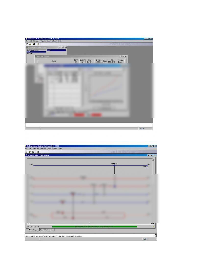
Minimum hot utility 580kW, Minimum cold utility 222.5kW
Composite curves:
Following the pinch design rules gives the following network:
(Note that from the top, the streams are cold utility, 1, 2, 4, 3, hot utility)
20