PROBLEM 18.16
For the assembly of Prob. 18.15, determine (a) the angular
momentum
B
H
of the assembly about point B, (b) the angle
formed by
B
H
and BA.
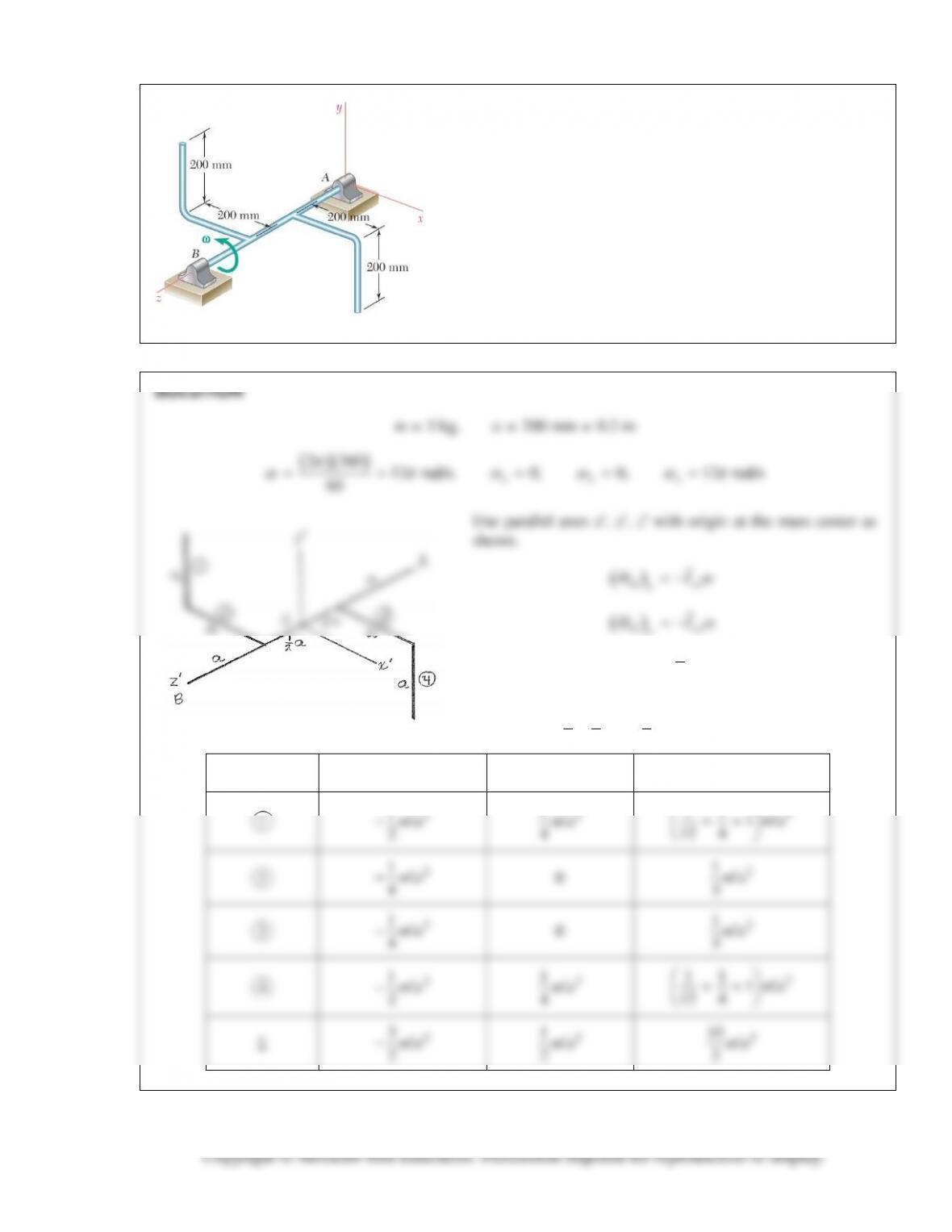
PROBLEM 18.15: Two L–shaped arms, each of mass 5 kg, are
welded at the one-third points of the 600 mm shaft AB to form
the assembly shown. Knowing that the assembly rotates at the
constant rate of 360 rpm, determine (a) the angular momentum
A
H
of the assembly about point A, (b) the angle formed by
A
H
and AB.
G yz
y
( )
Gz
z
HI
ω
=
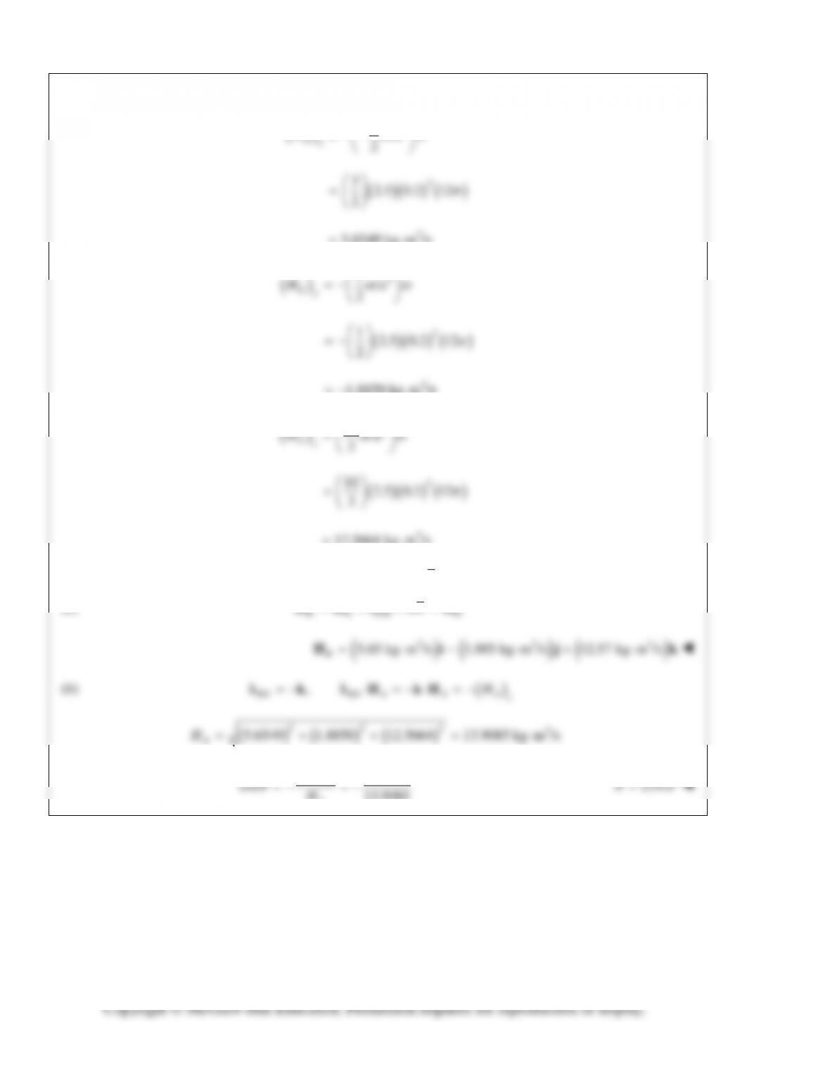
Segments 1, 2, 3, and 4, each of mass
2.5 kg,
′=m
contribute to
, and .
xz yz z
II I
Part
xz
I
yz
I
z
I
2
1
−ma
ma
2
ma
2
11
1
′
++
ma
2
1
−ma
2
1
ma
2
11
1
′
++
ma
PROBLEM 18.16 (Continued)
( )
2
3
2
Gx
H ma
ω
′
=−−
2
32.5 0.2 12
2
2
5.6549 kg m /s= ⋅
2
1
2
2
1.8850 kg m /s=−⋅
2
10
PROBLEM 18.17
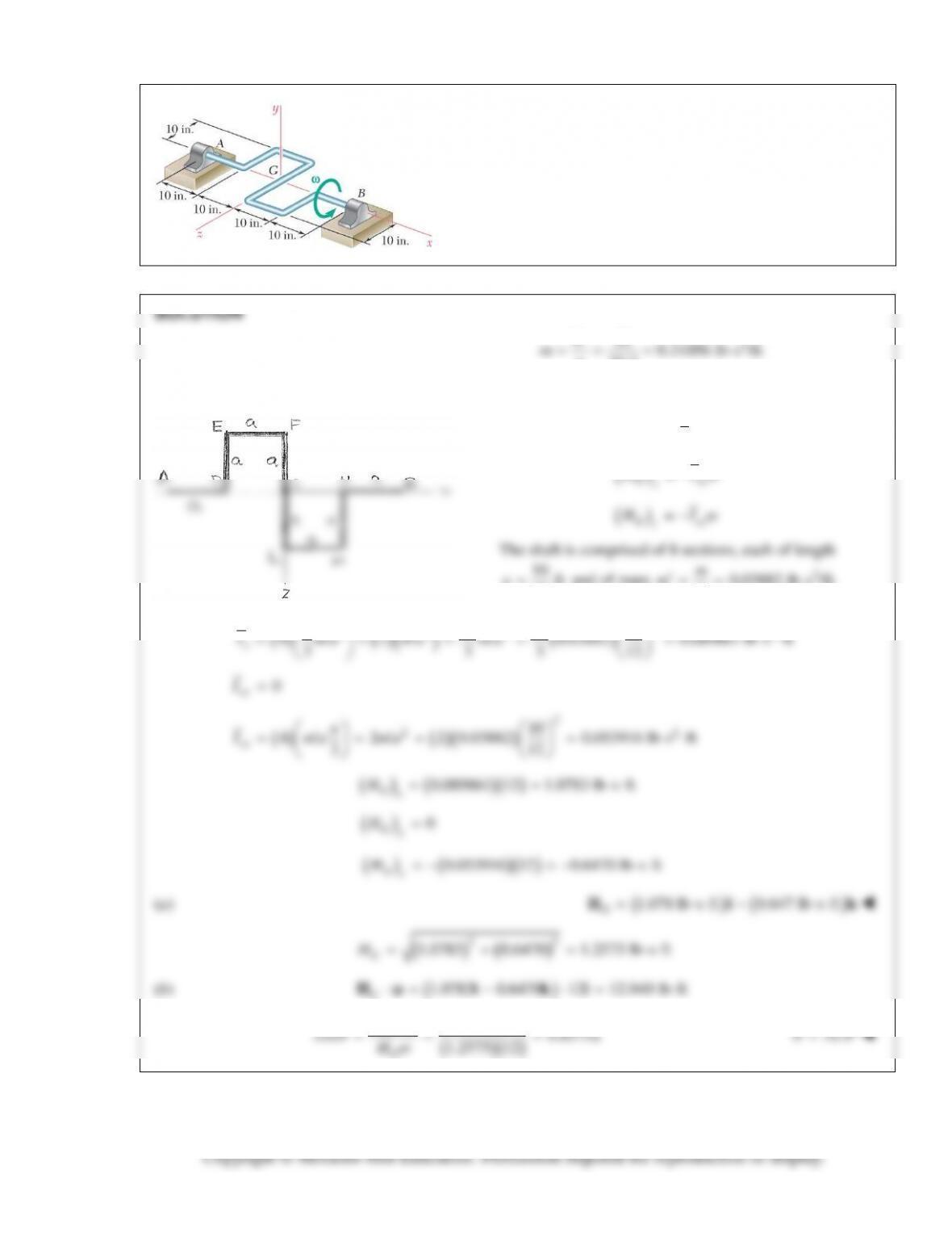
A 10-lb rod of uniform cross section is used to form the shaft
shown. Knowing that the shaft rotates with a constant angular
velocity
ω
of magnitude 12 rad/s, determine (a) the angular
momentum
G
H
of the shaft about its mass center G, (b) the
angle formed by
G
H
and the axis AB.
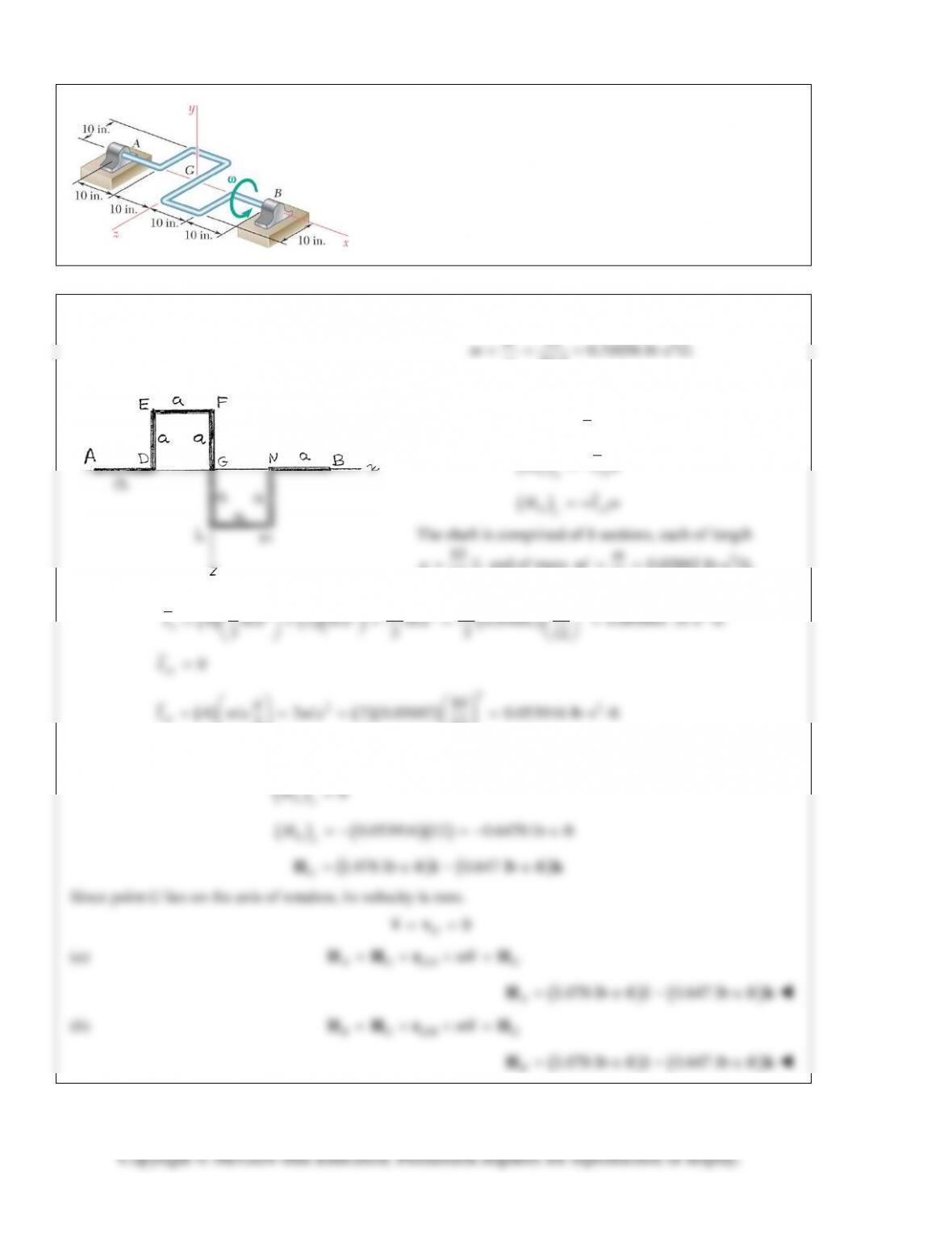
PROBLEM 18.18
Determine the angular momentum of the shaft of Prob. 18.17
about (a) point A, (b) point B.
SOLUTION
2
10 0.31056 lb s /ft
W
PROBLEM 18.19
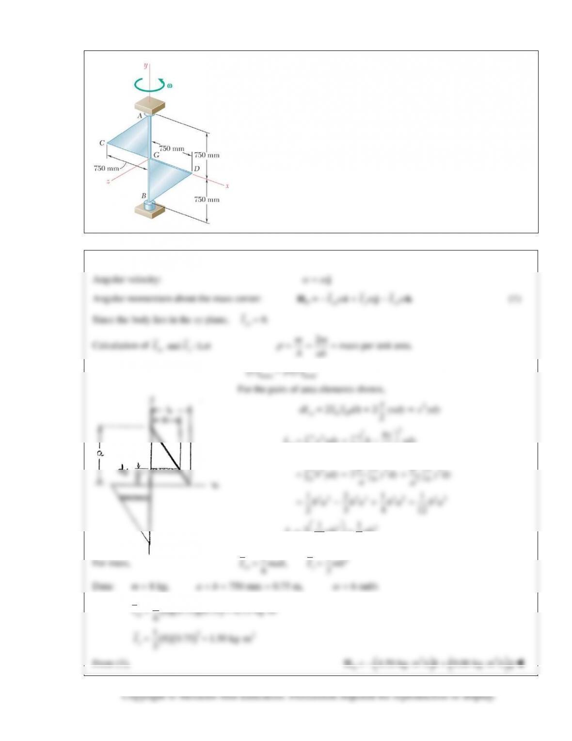
Two triangular plates, each of mass 8 kg, are welded to a vertical shaft
AB. Knowing that the system rotates at the constant rate ω = 6 rad/s,
determine its angular momentum about G.
SOLUTION
el el
2
xy
2
2
00
aa
xy
by
I x ydy b ydy
a
= = −
∫∫
22
2 23
2
0 00
a aa
bb
aa
∫ ∫∫
22 23 22 22
121 1
2 3 4 12
ba ba ba ba=−+=
33
11
212 6
y
I ab ab
= =
2
11
PROBLEM 18.20
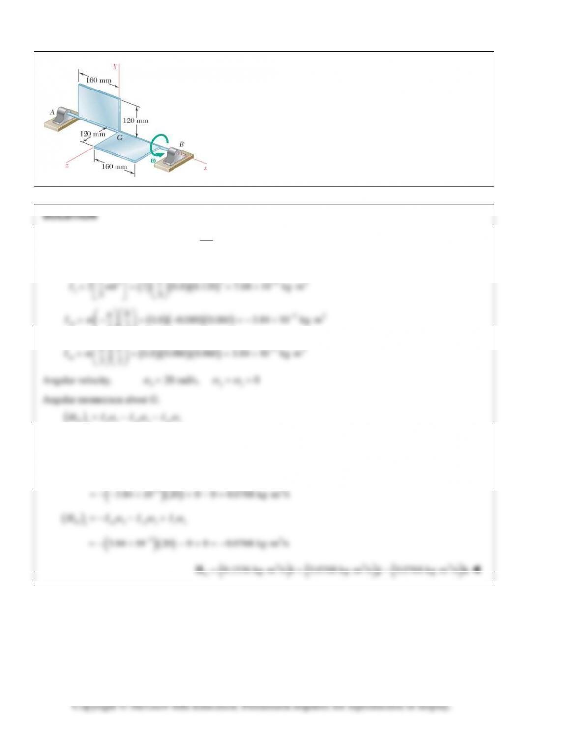
The assembly shown consists of two pieces of sheet aluminum of
uniform thickness and total mass 1.6 kg welded to a light axle
supported by bearings A and B. Knowing that the assembly
rotates with an angular velocity of constant magnitude
ω = 20 rad/s, determine the angular momentum
G
H
of the
assembly about point G.
Mass of each sheet
1.6 0.8 kg
2
m= =
Required moment and products of inertia.
2
2 32
11
−
PROBLEM 18.21
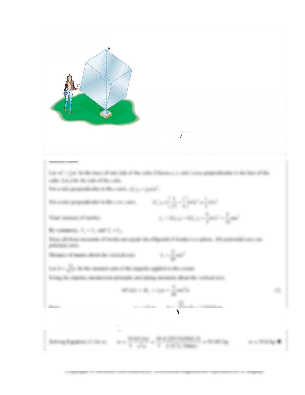
One of the sculptures displayed on a university campus consists
of a hollow cube made of six aluminum sheets, each
1.5 1.5 m,×
welded together and reinforced with internal braces
of negligible weight. The cube is mounted on a fixed base at A
and can rotate freely about its vertical diagonal AB. As she
passes by this display on the way to a class in mechanics, an
engineering student grabs corner C of the cube and pushes it
for 1.2 s in a direction perpendicular to the plane ABC with an
average force of 50 N. Having observed that it takes 5 s for the
cube to complete one full revolution, she flips out her
calculator and proceeds to determine the mass of the cube.
What is the result of her calculation? (Hint: The perpendicular
distance from the diagonal joining two vertices of a cube to any
of its other six vertices can be obtained by multiplying the side
of the cube by
2/3.)
vv
Data:
2
1.5 m, (1.5) 1.22474 m
3
ab= = =
21.25664 rad/s, 50 N, 1.2 s.
5Ft
π
ω
= = = ∆=
22
18 ( ) 18 (1.22474)(50)(1.2) 93.563 kg
55
(1.5) (1.25664)
bF t
ω
∆
PROBLEM 18.22
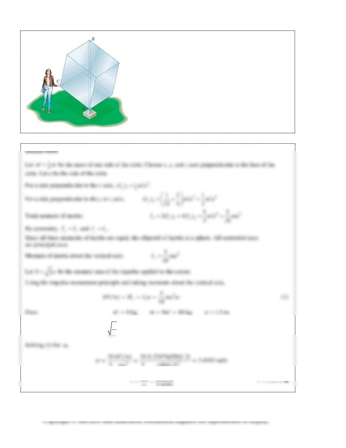
If the aluminum cube of Problem 18.21 were replaced by a
cube of the same size, made of six plywood sheets with mass
8 kg each, how long would it take for that cube to complete one
full revolution if the student pushed its corner C in the same
way that she pushed the corner of the aluminum cube?
21.22474 m, 50 N, 1.2 s
3
ba F t= = = ∆=
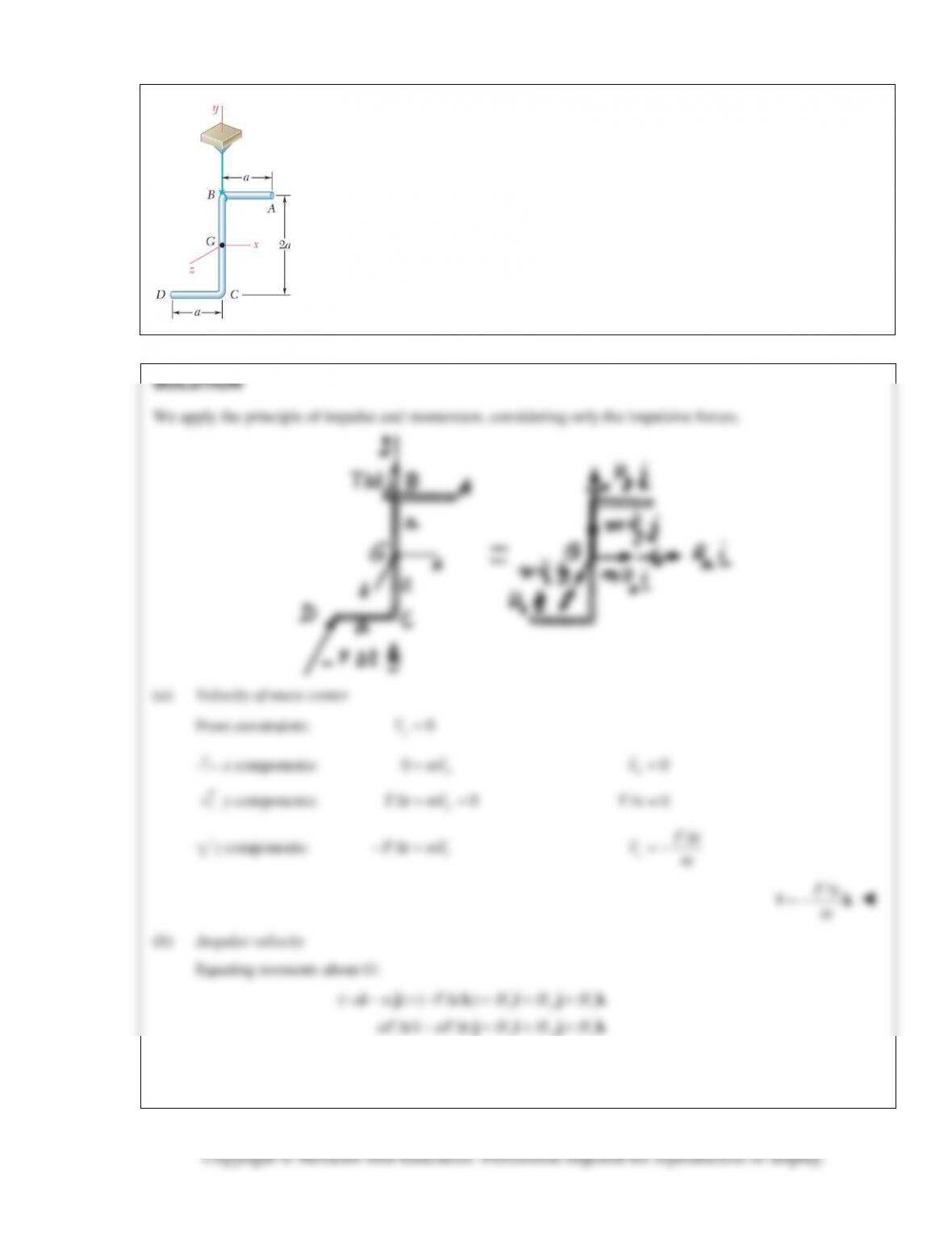
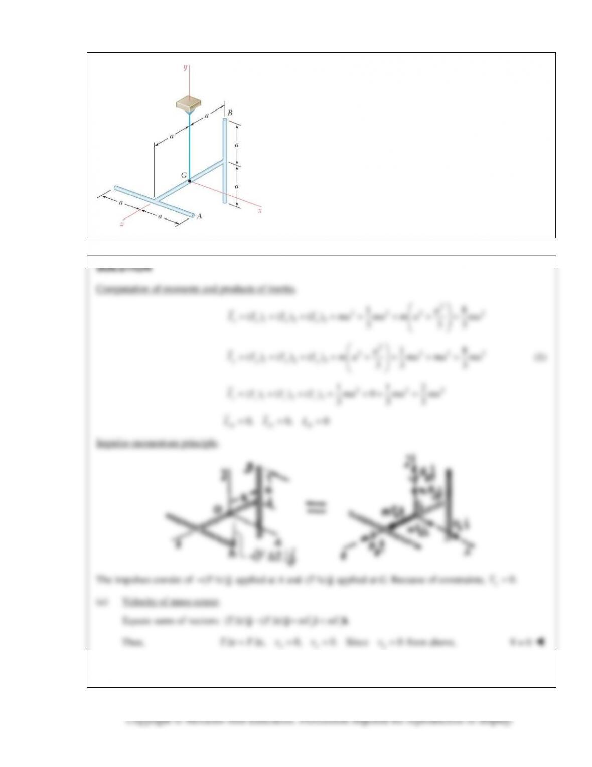
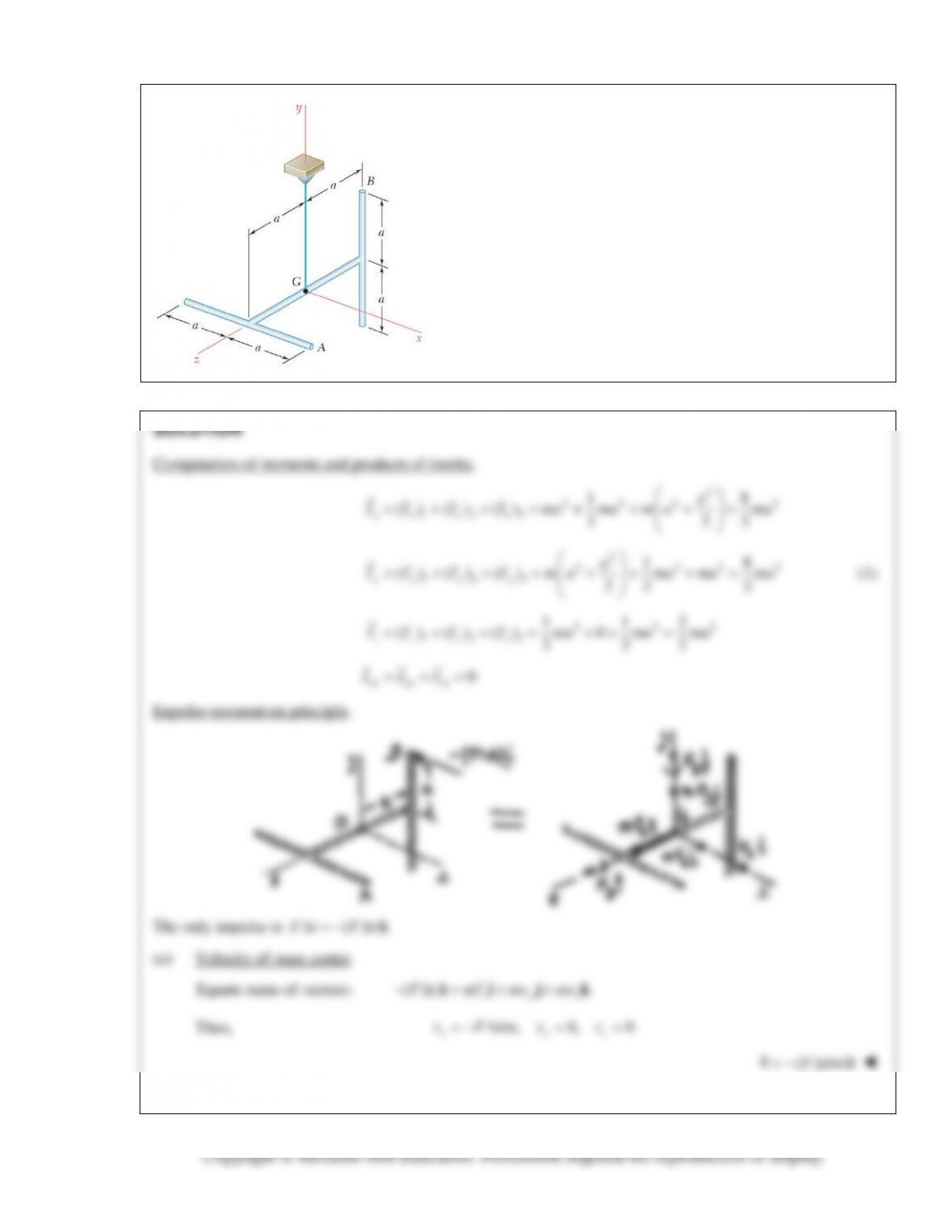
PROBLEM 18.23
A uniform rod of total mass m is bent into the shape shown and is suspended by a
wire attached at B. The bent rod is hit at D in a direction perpendicular to the plane
containing the rod (in the negative z direction). Denoting the corresponding impulse
by F∆t, determine (a) the velocity of the mass center of the rod, (b) the angular
velocity of the rod.
xyz
aF t aF t H H H
∆− ∆= + +
i ji jk
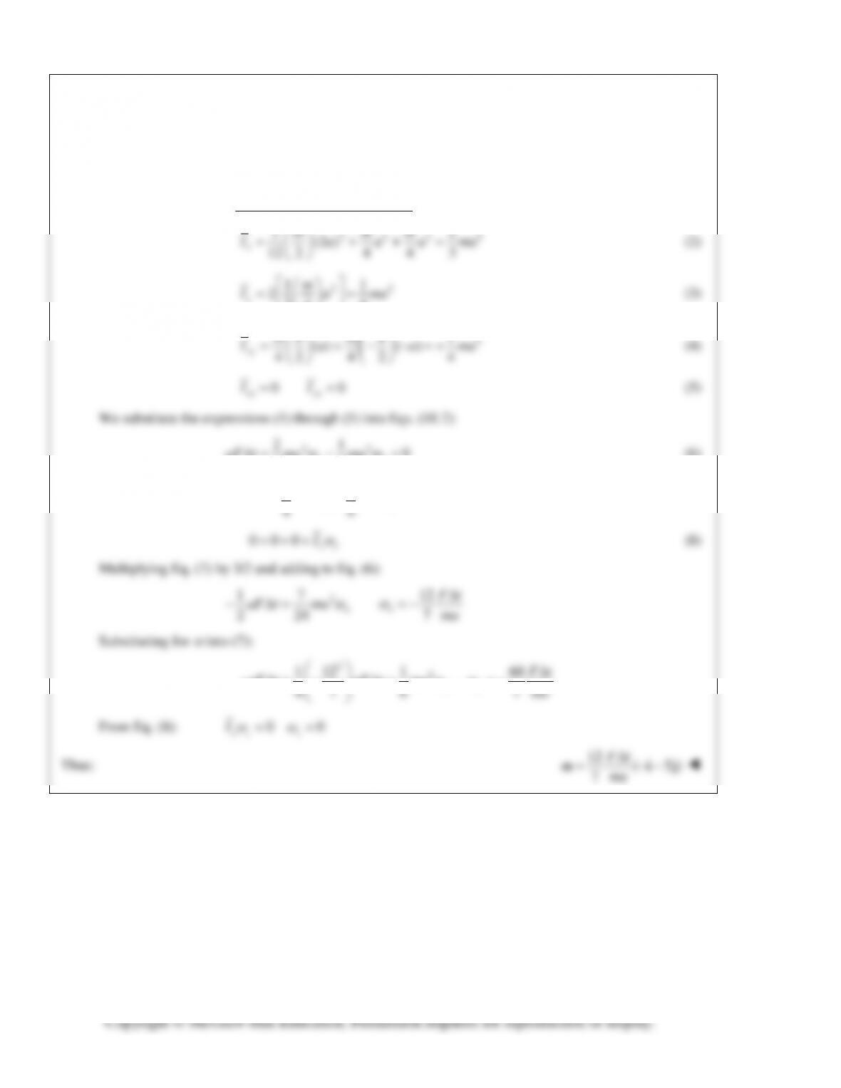
PROBLEM 18.23 (Continued)
Thus:
, ,0
xy z
H aF t H aF t H= ∆ =−∆ =
(1)
To determine angular velocity, we shall use Eqs. (18.7).
First, we determine the moments & products of inertia:
222 2
12
m mm
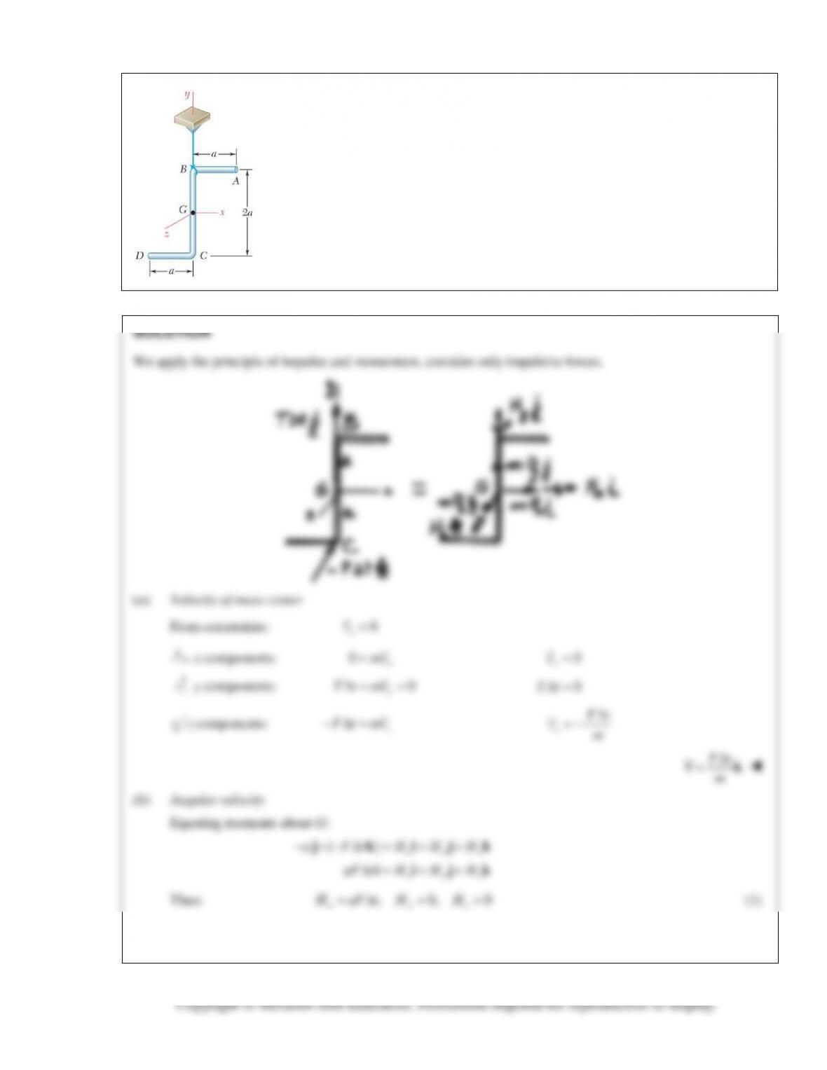
PROBLEM 18.24
Solve Problem 18.23, assuming that the bent rod is hit at C.
PROBLEM 18.23 A uniform rod of total mass m is bent into the shape shown and is
suspended by a wire attached at B. The bent rod is hit at D in a direction
perpendicular to the plane containing the rod (in the negative z direction). Denoting
the corresponding impulse by F∆t, determine (a) the velocity of the mass center of
the rod, (b) the angular velocity of the rod.
x yz
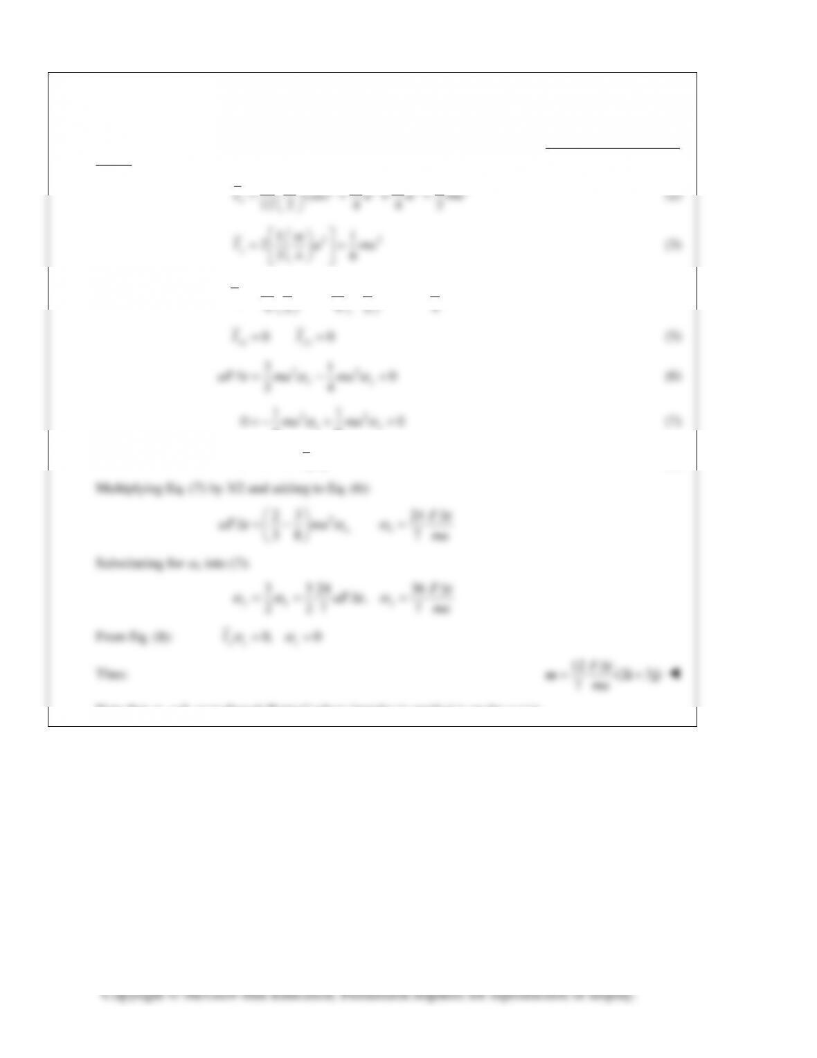
PROBLEM 18.24 (Continued)
To determine angular velocity, we shall use Eqs. (18.7) first, we determine the moments & products of
inertia:
222 2
12
12 2 4 4 3
x
m mm
22
11
234 6
y
m
I a ma
= =
(3)
2
1
() ( )
42 4 2 4
xy
ma m a
I a a ma
= + − −=+
(4)
PROBLEM 18.25
Three slender rods, each of mass m and length 2a, are welded
together to form the assembly shown. The assembly is hit at A in
a vertical downward direction. Denoting the corresponding
impulse by F
,t∆
determine immediately after the impact (a) the
velocity of the mass center G, (b) the angular velocity of the rod.
xz y
PROBLEM 18.25 (Continued)
(b) Angular velocity.
Equate moments about G:
( )( )
xyz
a a Ft H H H+ ×− ∆ = + +ik j i j k
()()
xyz
aF t aF t H H H− ∆ + ∆= + +k i i jk
PROBLEM 18.26
Solve Problem 18.25, assuming that the assembly is hit at B in the
negative x direction.
PROBLEM 18.25 Three slender rods, each of mass m and length
2a, are welded together to form the assembly shown. The
assembly is hit at A in a vertical downward direction. Denoting
the corresponding impulse by F
,t∆
determine immediately after
the impact (a) the velocity of the mass center G, (b) the angular
velocity of the rod.
PROBLEM 18.26 (Continued)
(b) Angular velocity.
Equate moments about G:
( )( )
xyz
a a Ft H H H− ×− ∆ = + +jk i i j k
()()
xyz
aF t aF t H H H∆ + ∆= + +k ji jk
PROBLEM 18.27
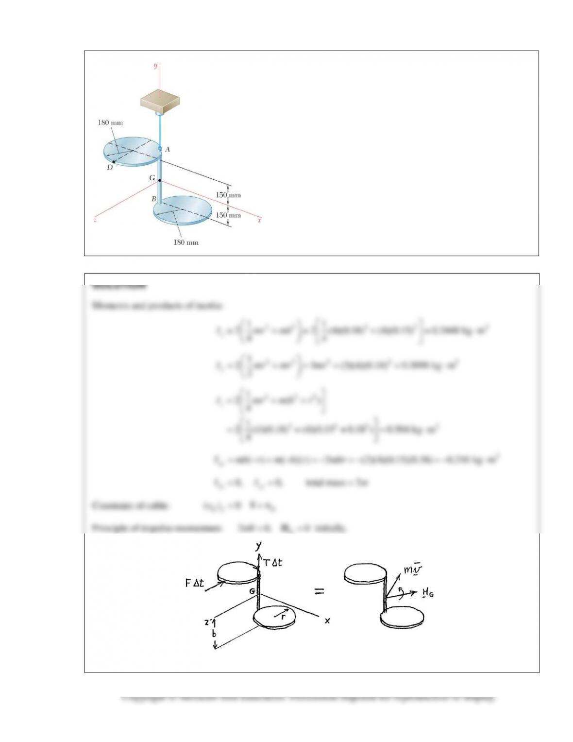
Two circular plates, each of mass 4 kg, are rigidly connected by
a rod AB of negligible mass and are suspended from Point A as
shown. Knowing that an impulse
(2.4 N s)t∆=− ⋅Fk
is
applied at Point D, determine (a) the velocity of the mass center
G of the assembly, (b) the angular velocity of the assembly.
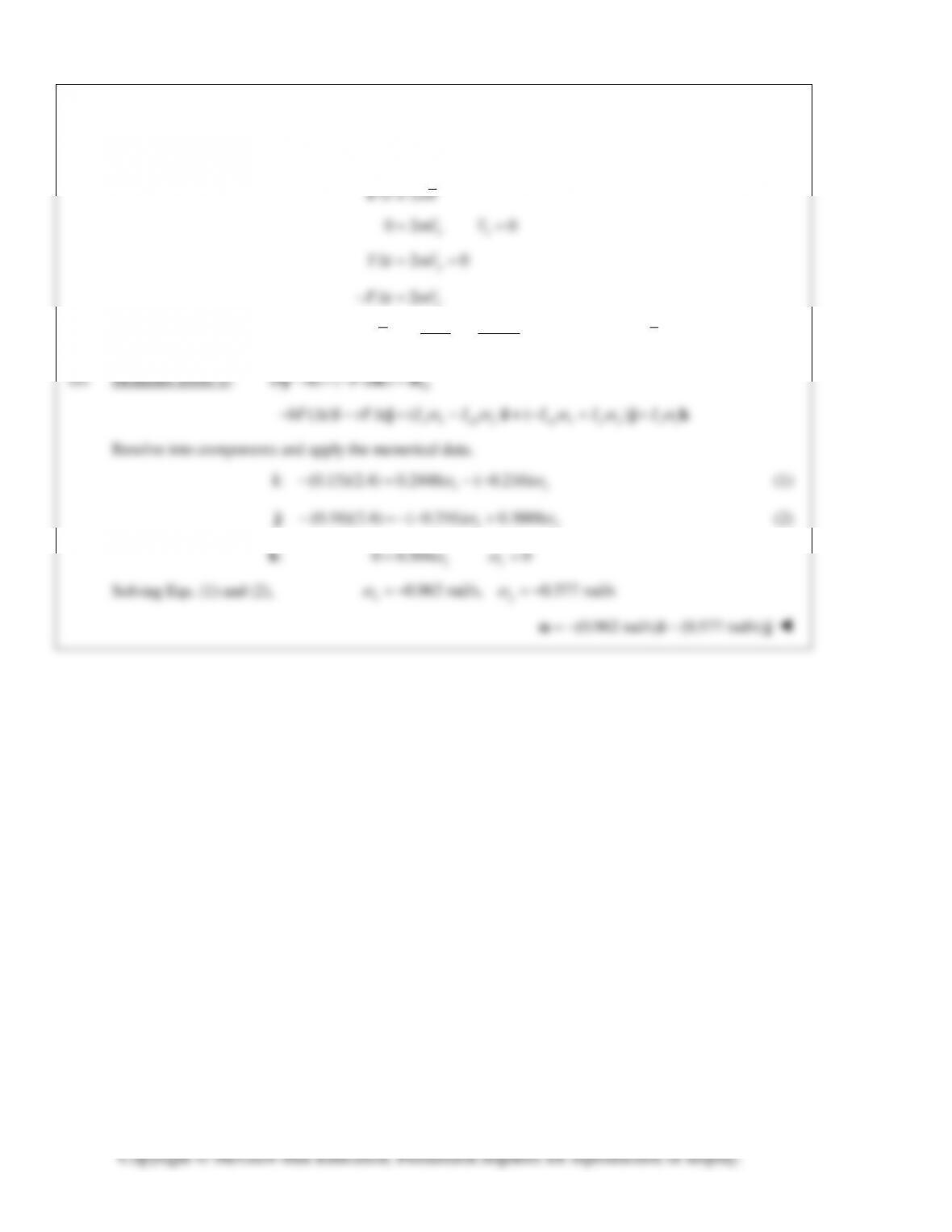
PROBLEM 18.27 (Continued)
(a) Direct components:
y
2
2.4 0.3 m/s
2 (2)(4)
z
z
F t mv
Ft
vm
− ∆=
∆
=−=− =−
(0.300 m/s)= −vk
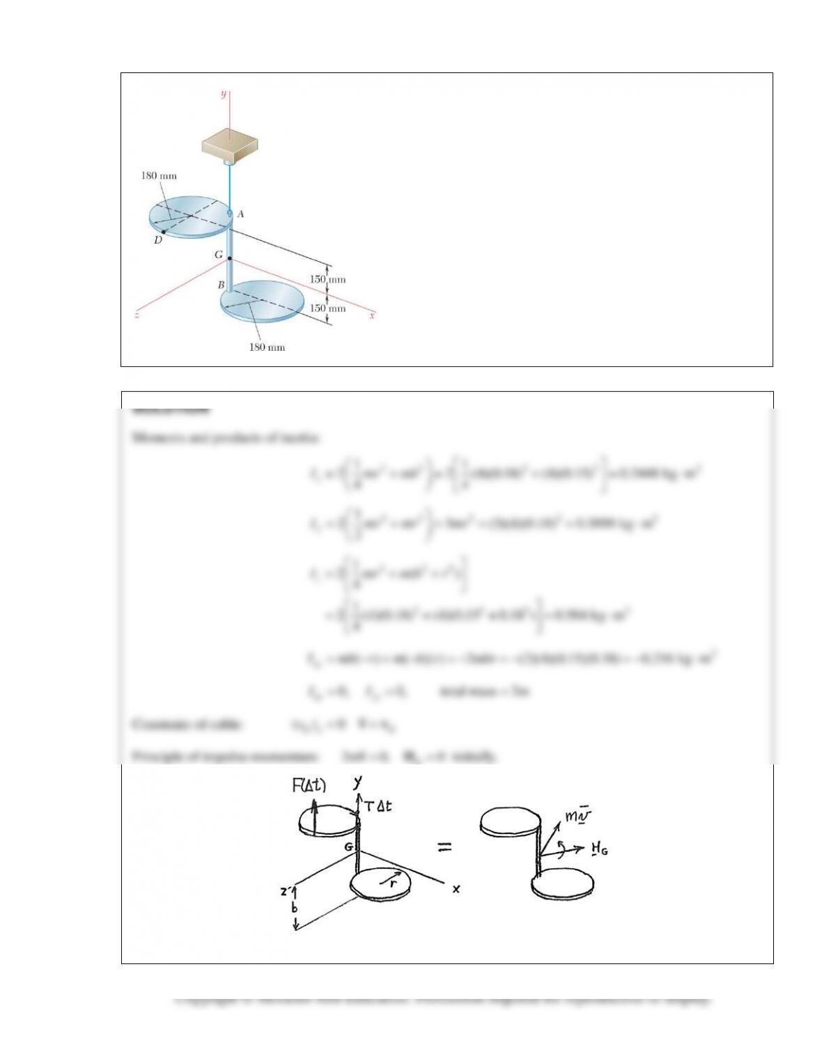
PROBLEM 18.28
Two circular plates, each of mass 4 kg, are rigidly connected by
a rod AB of negligible mass and are suspended from Point A as
shown. Knowing that an impulse
(2.4 N s)t∆= ⋅Fj
is applied
at Point D, determine (a) the velocity of the mass center G of
the assembly, (b) the angular velocity of the assembly.
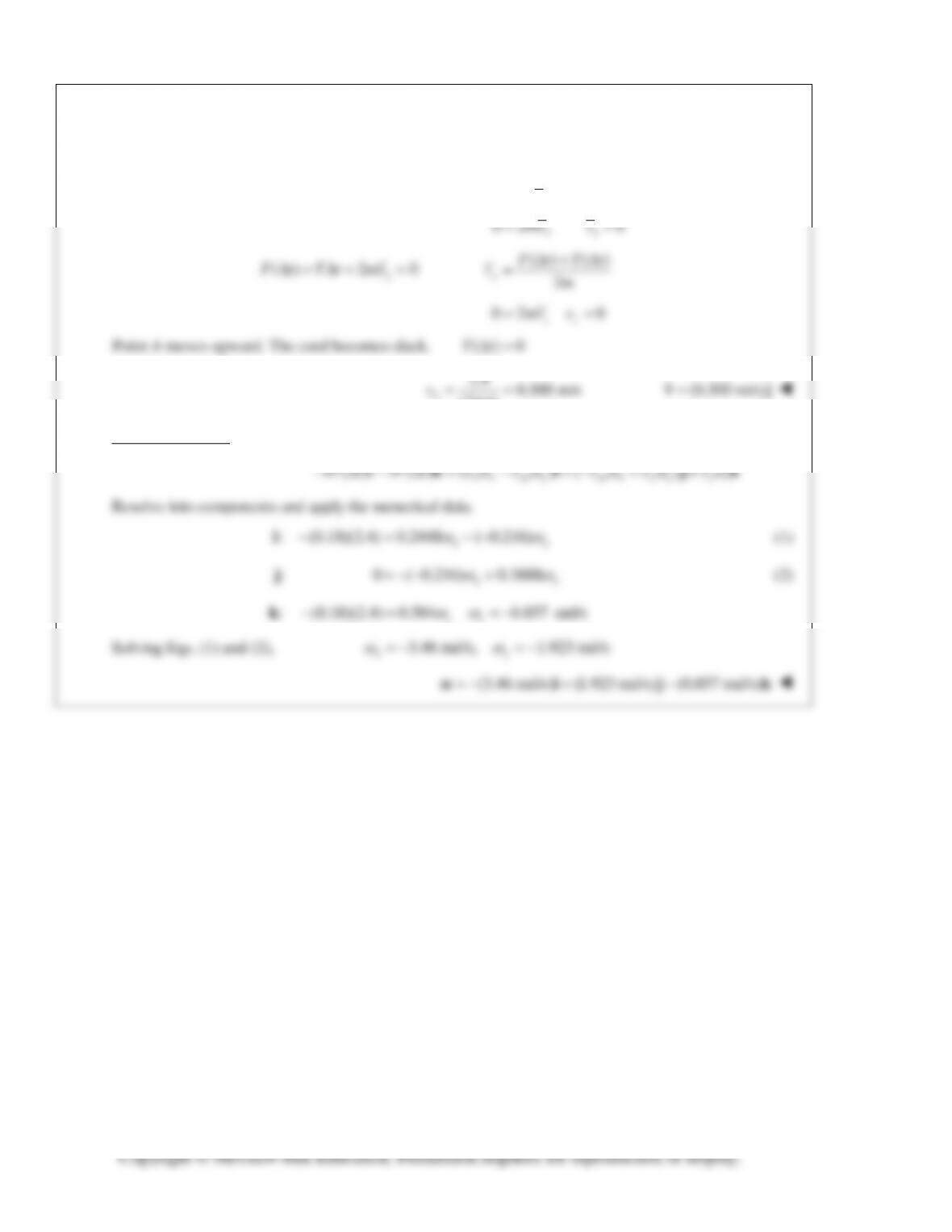
PROBLEM 18.28 (Continued)
(a) Direct components:
2tm∆=Fv