Problem Solutions – Chapter 6
12
6-43.*
Present state
Input
Next state
Output
A
B
C
A
B
C
STA
1
1
0
0
0
0
W
W
1
0
0
1
0
0
A
D AW BXY C
B
D AW
C
D B(X Y)
Z BXY C
The implementation consists of the logic represented by the
6-44.
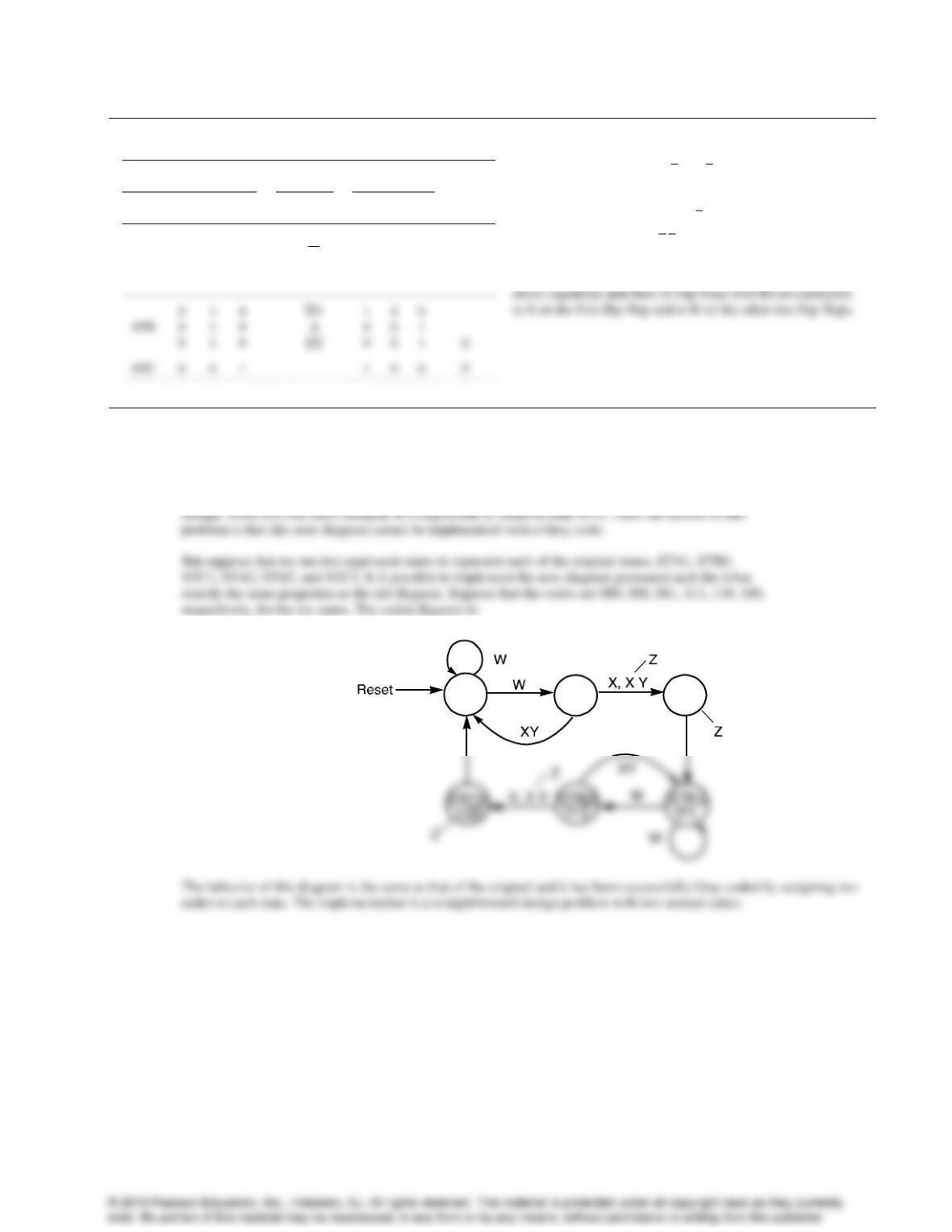
This state diagram has a closed loop of three transitions (STA to STB to STC to STA). In a Gray code,
only one bit may change in going from one state to another. Any state machine diagram with a loop of
an odd number of transitions is impossible to encode with a Gray code. For example, to go from STA to
STB suppose bit B1 of the code changes. Then to go from STB to STC, some other bit, say B2 must
Default: Z = 0
STA1 STB1
000 001 STC1
011
Problem Solutions – Chapter 6
13
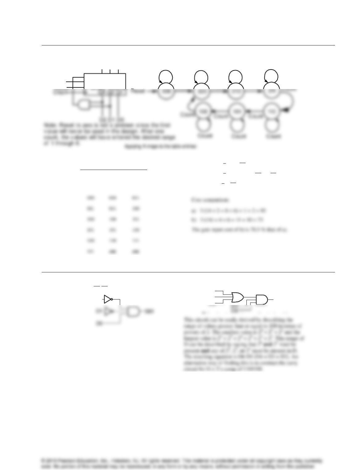
6-45.
a)
Parallel Load
Load
D4 D2 D1
0 0 1
b)
Cnt
Count Count
Count
Count
Count
Count
State
Cnt = 0
Cnt = 1
000
000
001
001
001
010
010
010
011
100
100
101
101
101
110
110
110
111
111
ddd
ddd
Q4
D Q4 C Q4 Q2 Q1Q2 C
Q2
D Q2 C Q1Q2 C Q4 Q2 Q1
Q1
D Q1C Q1C
6-46.
a)
DE1 D4 D2 D1
D2
b)
GTE100
D2
D3
Problem Solutions – Chapter 6
14
6-47.
Binary
BCD (C0 = 0)
BCD (C0 =
B3B2B1B0
C4D3D2D1D0
C4D3D2D1D0
0 0 0 0
0 0 0 1
0 0 1 0
0 0 0 0 0
0 0 0 0 1
0 0 0 1 0
0 0 0 0 1
0 0 0 1 0
0 0 0 1 1
0
For C 0,
C4 B3 B2 B3 B1
D3 B3 B2 B1
D2 B3 B2 B2 B1
D1 B3 B1 B3 B2 B1
D0 B0
D2 C0 (B3 B2 B2 B1) C0 (B3 B2 B1 B3 B2 B0 B2 B1 B0 B3 B2 B1 B0)
D1 C0 (B3 B1 B3 B2 B1) C0 (B3 B1 B0 B3 B1 B0 B3 B1 B0 B3 B2 B1 B0)
D0 C0 B0 C0 B0
Optimizing,
C4 B3 (B2 B1 C0 B0)
6-48.
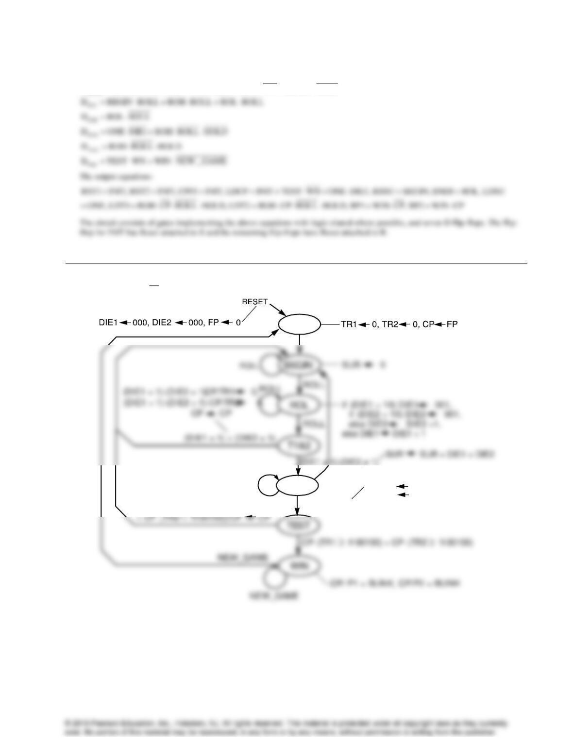
a) Transition constraint checking for Figure 6-30.
Constraint 1: Constraint 2:
INIT: No possible conflicts since a single transition. Condition implicitly = 1 OK
BEGIN: ROLL ROLL 0
OK
BEGIN: ROLL ROLL 1
OK
ROL: ROLL ROLL 0
OK
ROL: ROLL ROLL 1
OK
Problem Solutions – Chapter 6
15
The flip-flop input equations:
INIT
BEGIN
D INIT(t 1) WIN NEW _ GAME
D BEGIN(t 1) INIT ONE DIE1 TEST WN BEGIN ROLL
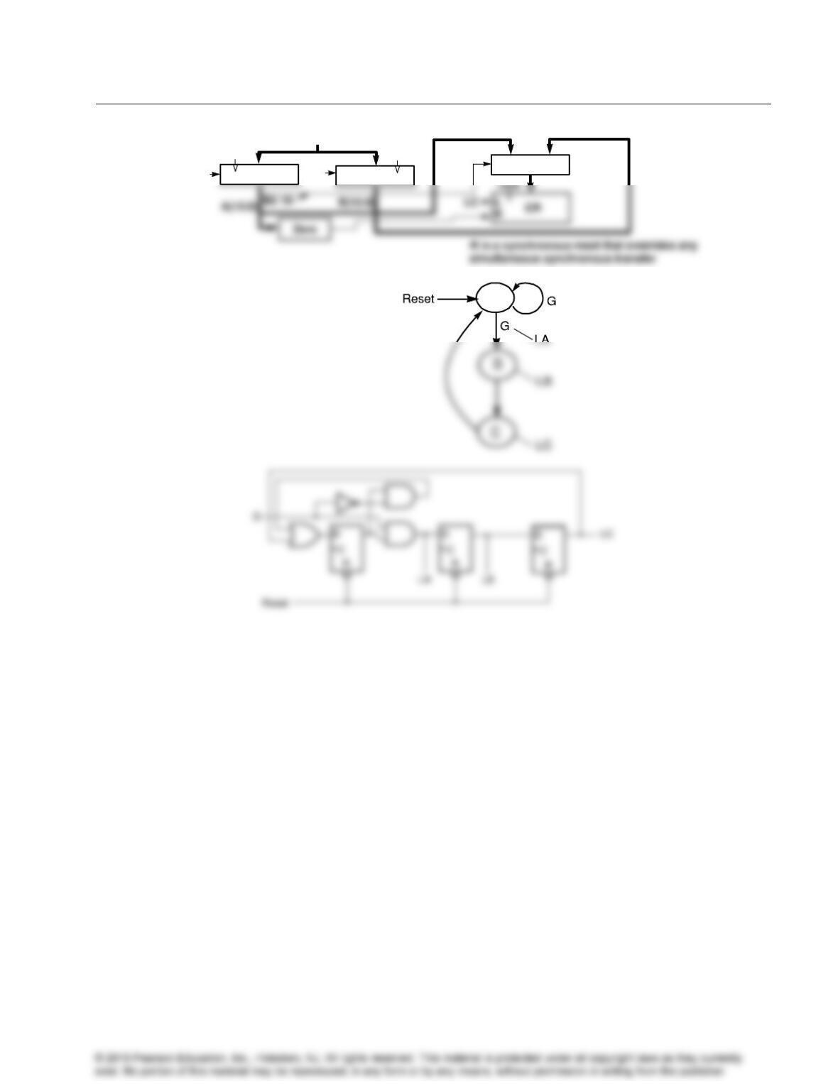
6-49.+
Default:
P1 CP, P2 CP
CP/TR1 TR1 + SUR,
INIT
ROH
ROLL
ROLL· HOLD
ROLL· HOLD
CP/TR2 TR2 + SUR
(CP· (TR1 1100100)
Problem Solutions – Chapter 6
16
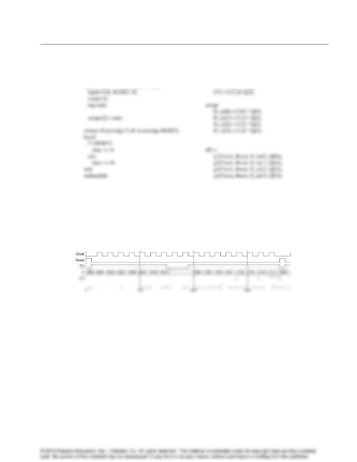
6-50.*
A
Def ault: LA = 0,
LB = 0, LC = 0
CLK
L
L
L
R
Zero
A(15:0)
B(15:0)
IN
AR
BR
MUX
1
0
S
LA
LB
A(14:0)||0
B(14:0)||0
CLK
Problem Solutions – Chapter 6
17
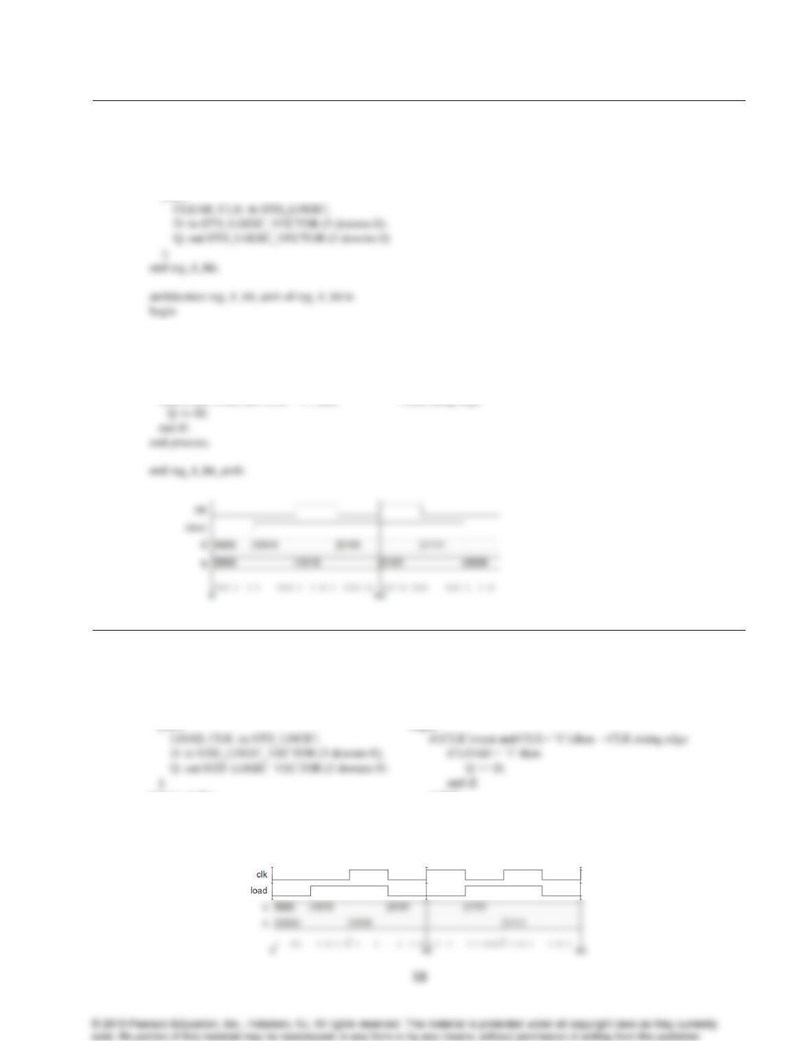
6-51.
// 4-bit Binary Counter
// Positive Edge-Triggered D Flip-Flop with Reset:
module dff_v(CLK, RESET, D, Q);
module Counter_4bit (Clock, Reset, EN, Q, CO) ;
input Clock, Reset, EN ;
output [3:0] Q ;
output CO ;
wire[3:0] Q ;
wire [3:0] C, D_in;
// (continued in next column)
C[0] = EN,
C[1] = C[0] & Q[0],
C[2] = C[1] & Q[1],
C[3] = C[2] & Q[2],
endmodule
Problem Solutions – Chapter 6
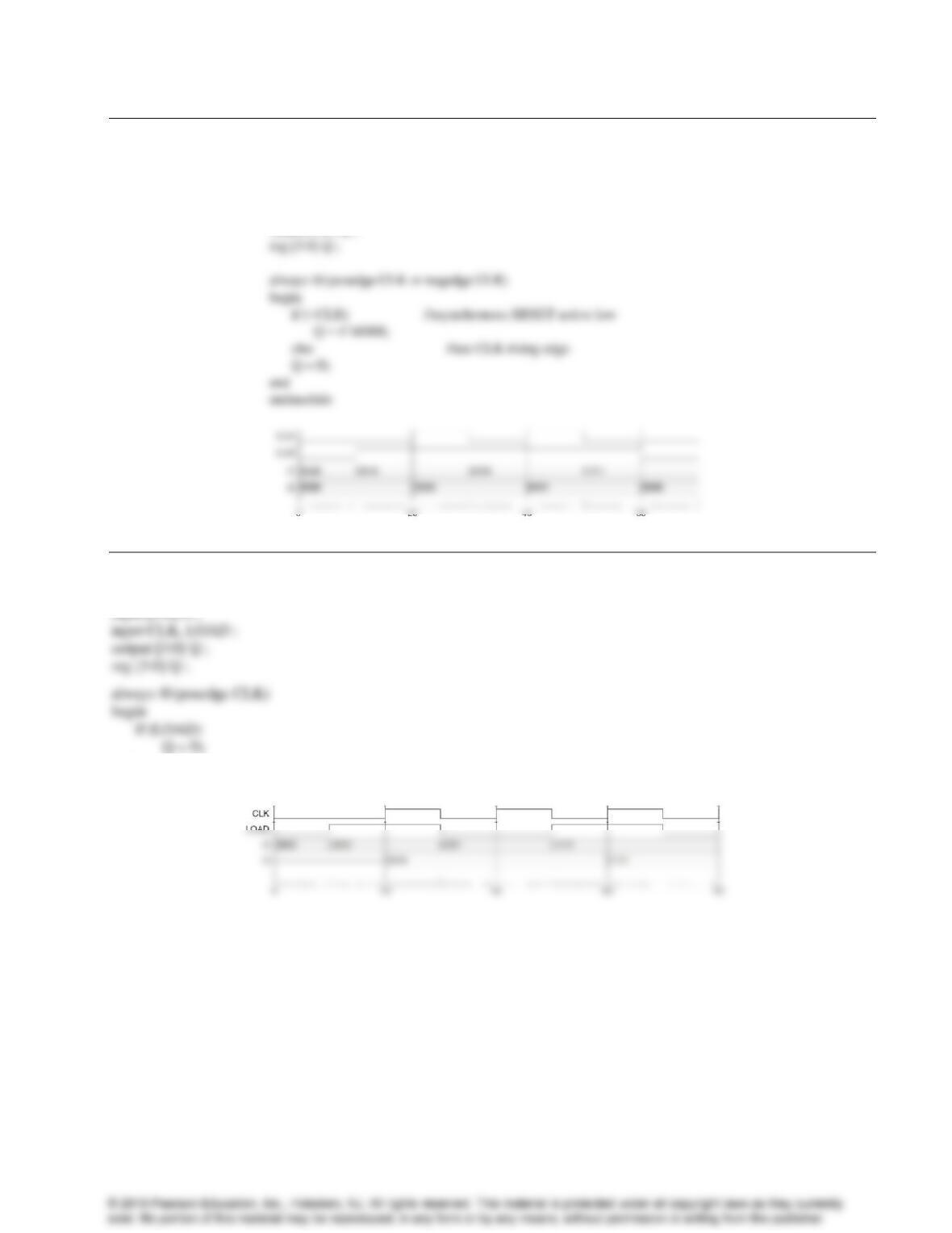
6-52. *
library IEEE;
use IEEE.std_logic_1164.all;
entity reg_4_bit is
port (
process (CLK, CLEAR)
begin
if CLEAR = ‘0’ then —asynchronous RESET active Low
Q <= “0000”;
elsif (CLK’event and CLK= ‘1’) then —CLK rising edge
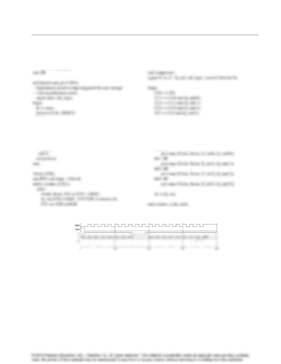
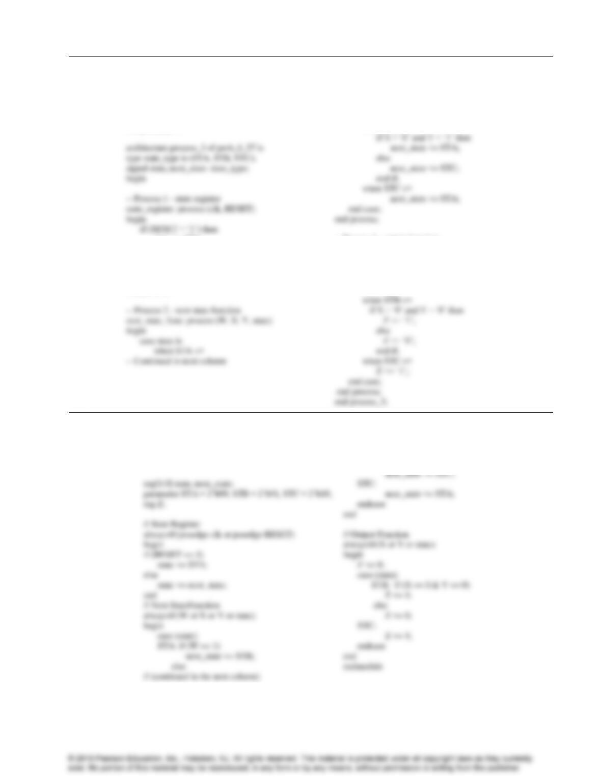
6-53.
library IEEE;
use IEEE.std_logic_1164.all;
entity reg_4_bit is
port (
end reg_4_bit;
— (continued in next column)
architecture reg_4_bit_load_arch of reg_4_bit is
begin
process (CLK)
begin
end if;
end process;
endreg_4_bit_load_arch;
Problem Solutions – Chapter 6
19
6-54.
library ieee;
use ieee.std_logic_1164.all;
entity dff is
port(CLK, RESET, D: in std_logic;
Q : out std_logic);
begin
if (RESET = ‘1’) then
state <= ‘0’;
else
if (CLK’event and ClK = ‘1’) then
state <= D;
end if;
);
end counter_4_bit;
architecture counter_4_bit_arch of counter_4_bit is
component dff
port(CLK, RESET, D: in std_logic;
Q: out std_logic
);
D_in(0) <= C(0) xor Q_out(0);
D_in(1) <= C(1) xor Q_out(1);
D_in(2) <= C(2) xor Q_out(2);
D_in(3) <= C(3) xor Q_out(3);
bit0: dff
Problem Solutions – Chapter 6
20
6-55. *
module register_4_bit (D, CLK, CLR, Q) ;
input [3:0] D ;
input CLK, CLR ;
output [3:0] Q ;
6-56.
module register_4_bit_load (D, CLK, LOAD, Q) ;
end
endmodule
Problem Solutions – Chapter 6
21
6-57. *
library IEEE;
use IEEE.std_logic_1164.all;
entity prob_6_57 is
port (clk, RESET, W, X, Y : in STD_LOGIC;
Z : out STD_LOGIC);
end prob_6_57;
state <= STA;
else if (CLK’event and CLK=’1’) then
state <= next_state;
end if;
end if;
end process;
if W = ‘1’ then
next_state <= STB;
else
next_state <= STA;
end if;
when STB =>
— Process 3 – output function
output_func: process (X, Y, state)
begin
case state is
when STA =>
Z <= ‘0’;
6-58. *
// State Diagram in Figure 6-38 using Verilog
module prob_6_58 (clk, RESET, W, X, Y, Z);
input clk, RESET, W, X, Y;
output Z;
next_state <= STA;
STB: if (X == 0 & Y == 1)
next_state <= STA;
else