Problem Solutions – Chapter 4
21
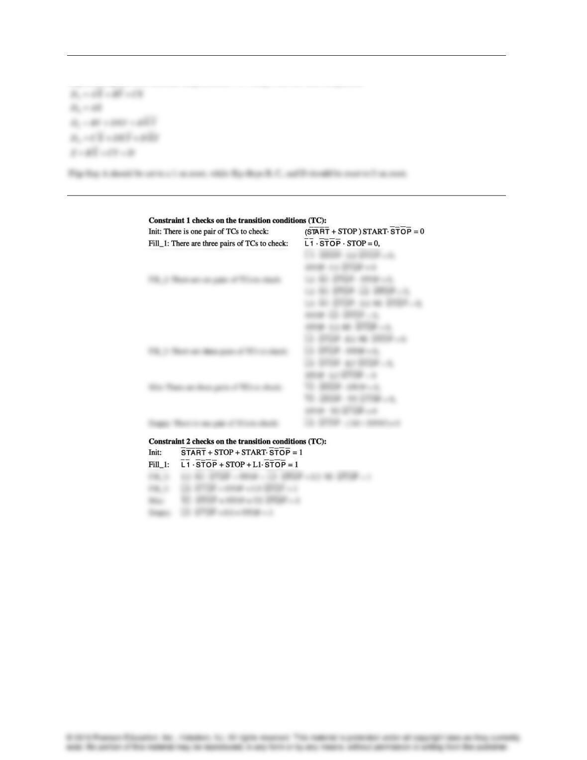
4-36.
Implementing the state-machine diagram from 4-35 using a one-hot state assignment:
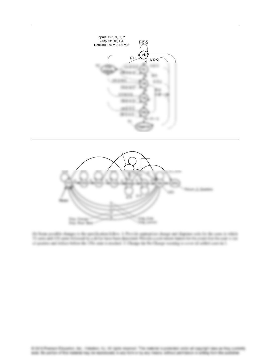
4-37.
Problem Solutions – Chapter 4
4-38.*
4-39.
NoCh
(a)
D
D
D
LT2Q
No_Change
D R
22
Problem Solutions – Chapter 4
23
4-40.
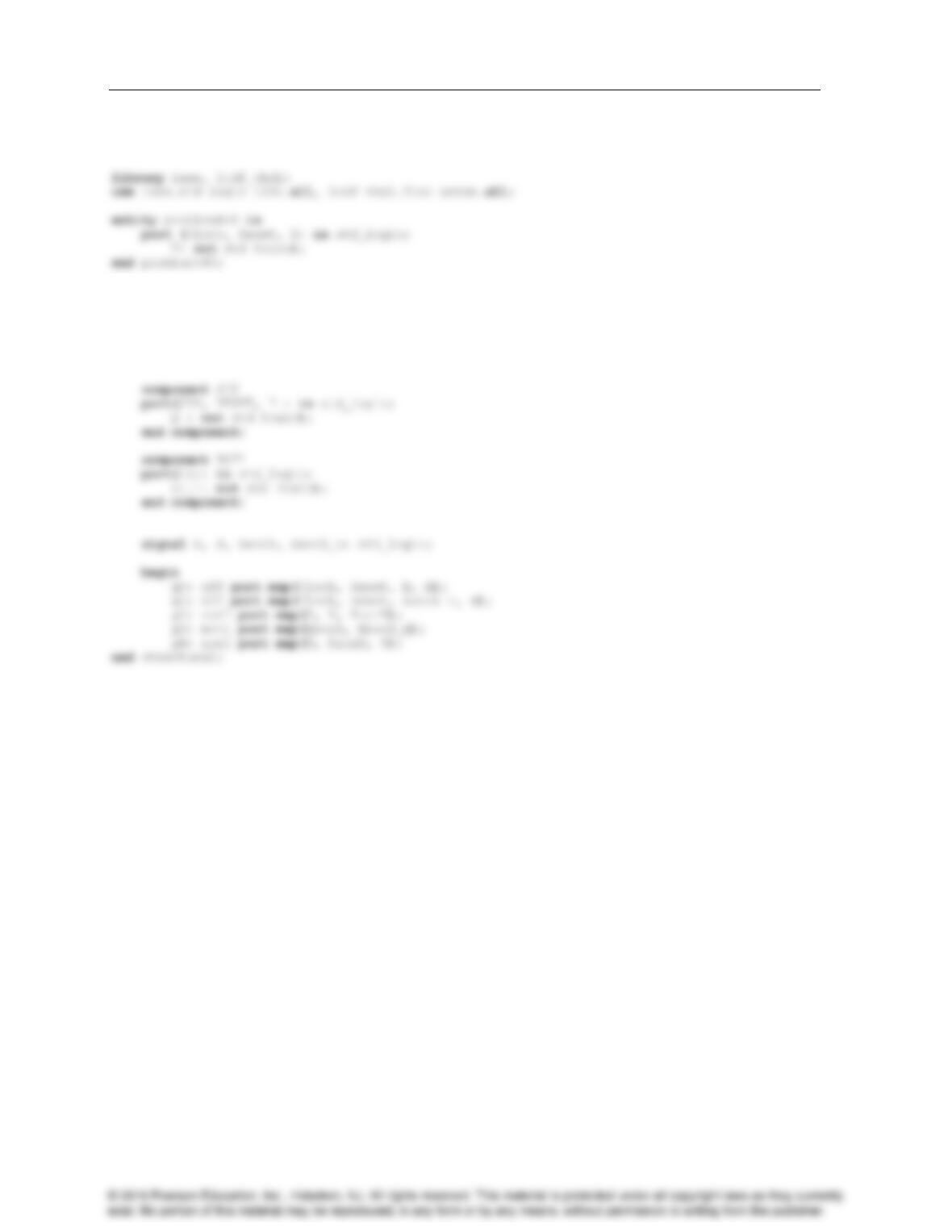
The schematic in Figure 4-49 does not include a reset signal. The model below includes a reset to make the model simulate
correctly.
architecture structural of problem440 is
component xor2
port(in1, in2: in std_logic;
out1: out std_logic);
end component;
Problem Solutions – Chapter 4
24
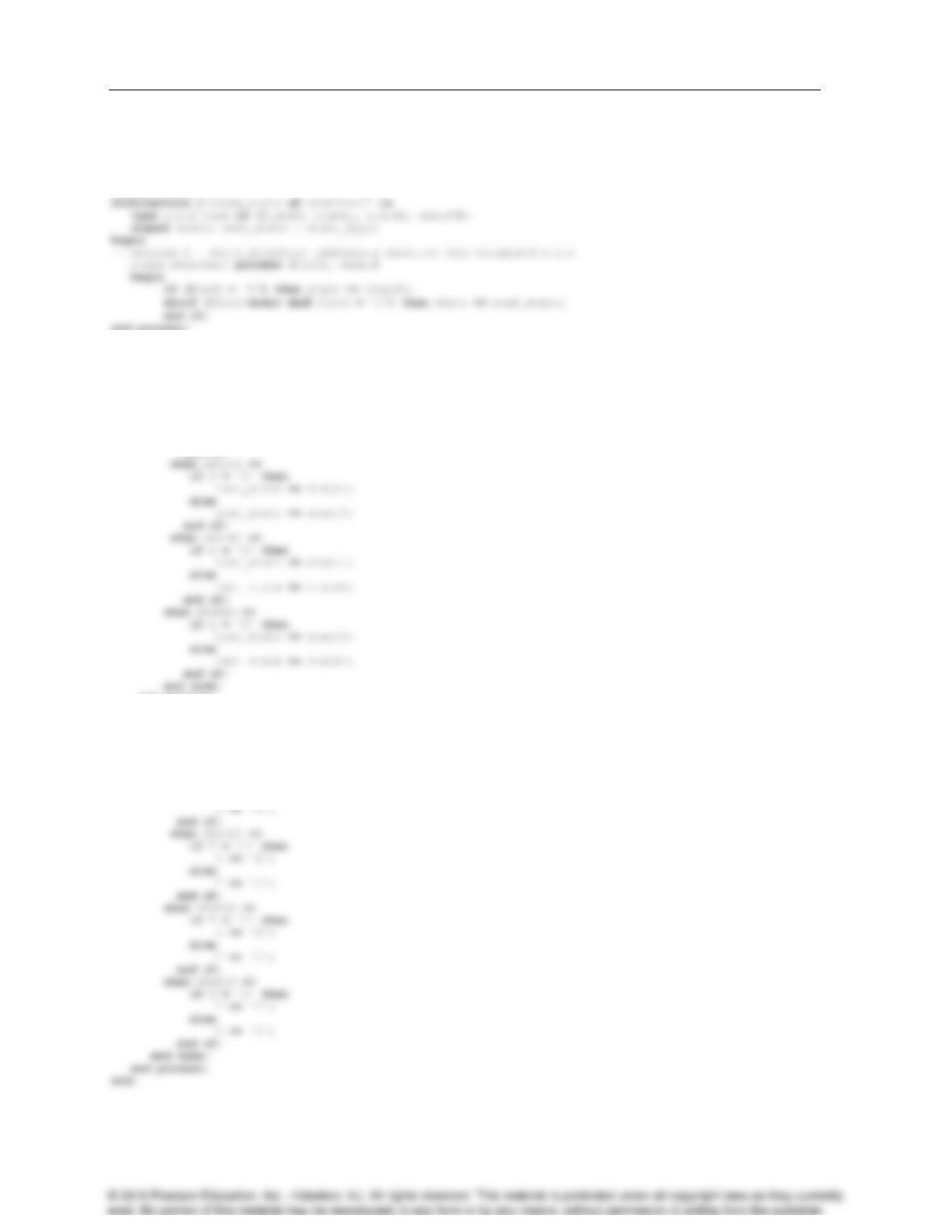
4-41.
library ieee;
use ieee.std_logic_1164.all;
entity problem441 is
port(Clock, X, Reset: in std_logic;
Y: out std_logic);
end problem441;
end process;
—- Process 2 – next_state_function: implements next state as function of input X and state.
next_state_func: process (X, state)
begin
case state is
when state0 =>
if X = ‘1’ then
next_state <= state0;
else
next_state <= state1;
end if;
end process;
— Process 3 – output_function: implements output as function of input X and state.
output_func: process (X, state)
begin
case state is
when state0 =>
if X = ‘1’ then
Y <= ‘1’;
else
Problem Solutions – Chapter 4
25
4-42.*
library IEEE;
use IEEE.std_logic_1164.all;
architecture mux_4to1_arch of mux_4to1 is
begin
4-43.
library IEEE;
use IEEE.std_logic_1164.all;
architecture mux_4to1_arch of mux_4to1 is
begin
Problem Solutions – Chapter 4
4-44.+
library IEEE;
use IEEE.std_logic_1164.all;
entity serial_BCD_Ex3 is
port (clk, reset, X : in STD_LOGIC;
Z : out STD_LOGIC);
end serial_BCD_Ex3;
— Process 2 – next state function
next_state_func: process (X, state)
begin
case state is
when Init =>
if (X = ‘0’) then
next_state <= B10;
else
next_state <= B11;
end if;
when B10 =>
if (X = ‘0’) then
else
next_state <= B31;
end if;
when B3X0 =>
next_state <= Init;
when B31 =>
if (X = ‘0’) then
Z <= ‘1’;else
Z<= ‘0’;
end if;
when B11 =>
Z <= X;
when B20 =>
Z <= X;
when B21 =>
if (X = ‘0’) then
Z <= ‘1’;
else
26
Problem Solutions – Chapter 4
27
4-45.
library IEEE;
use IEEE.std_logic_1164.all;
entity prob_5_43 is
port (clk, reset : in STD_LOGIC;
X : in STD_LOGIC_VECTOR(2 downto 1) ;
Z : out STD_LOGIC);
end prob_5_43;
— Process 2 – next state function
next_state_func: process (X, state)
begin
case state is
when A =>
case X is
when “00” =>
next_state <= A;
when “01” =>
next_state <= B;
when “10” =>
next_state <= D;
when others => next_state <= A;
end case;
when C =>
case X is
when “00” =>
next_state <= A;
when “01” =>
next_state <= A;
when D =>
case X is
when “00” =>
next_state <= C;
when “01” =>
next_state <= B;
when “10” =>
when “00” =>
Z <= ‘0’;
when “01” =>
Z <= ‘0’;
when “10” =>
Z <= ‘1’;
when “11” =>
Z <= ‘0’;
when others => Z <= ‘X’;
end case;
when B =>
case X is
when “01” =>
Z <= ‘0’;
when “10” =>
Z <= ‘1’;
when “11” =>
Z <= ‘0’;
when others => Z <= ‘X’;
end case;
when D =>
Problem Solutions – Chapter 4
4-46.
library IEEE;
use IEEE.std_logic_1164.all;
entity prob_5_44 is
port (clk, reset,
— Process 1 – state register
state_register: process (clk, reset)
begin
— Process 2 – next state function
next_state_func: process (X, state)
begin
case state is
when A =>
when C =>
if X = ‘0’ then
next_state <= A;
else
when E =>
if X = ‘0’ then
next_state <= C;
else
end case;
end process;
— Process 3 -output function
output_func: process (X, state)
28
Problem Solutions – Chapter 4
29
4-47.
library IEEE;
use IEEE.std_logic_1164.all;
entity prob_5_46 is
if (reset = ‘1’) then
state <= Init;
else if (CLK’event and CLK= ‘1’) then
state <= next_state;
end if;
end if;
end process;
— Process 2 – next state function
next_state_func: process (NI, Start, Stop, L0, L1, L2, L3, TZ, state)
begin
if Stop = ‘1’ then
next_state <= Init;
when Fill_3 =>
if L3 = ‘1’ then
next_state <= Mix;
next_state <= Empty;
end if;
end case;
end if;
end process;
— Process 3 – output function
output_func: process (L2, L3, NI, TZ, Stop, state)
begin
MX <= ‘0’;
PST <= ‘0’;
TM <= ‘0’;
V1 <= ‘0’;
Problem Solutions – Chapter 4
4-48.
library IEEE;
use IEEE.std_logic_1164.all;
entity prob_5_47 is
— Process 1 – state register
state_register: process (clk, reset)
begin
— Process 2 – next state function
next_state_func: process (CR, N, D, Q, state)
begin
case state is
next_state <= S15;
elsif D = ‘1’ then
next_state <= S20;
elsif D = ‘1’ then
next_state <= S25;
elsif Q = ‘1’ then
next_state <= S25;
next_state <= S25;
elsif D = ‘1’ then
next_state <= S25;
elsif Q = ‘1’ then
next_state <= S25;
30
.
Problem Solutions – Chapter 4
31
4-49.
The schematic in Figure 4-49 does not include a reset signal. The model below includes a reset to make the model simulate
correctly.
module problem449(Clock, Reset, X, Y);
input Clock, Reset, X;
4-50.
The schematic in Figure 4-49 does not include a reset signal. The model below includes a reset to make the model simulate
correctly.
always @(posedge Clock or posedge Reset)
begin
if (Reset)
state <= state0;
else
state <= next_state;
end
always @(state or X)
begin
Problem Solutions – Chapter 4
4-51.
module problem_6_38 (S, D, Y) ;
always @(S or D)
begin
4-52.*
module problem_6_39 (S, D, Y) ;
input [1:0] S ;
always @(S or D)
begin
if (S == 2′ b00) Y <= D[0];
32
Problem Solutions – Chapter 4
33
4-53.+
//Serial BCD to Excess 3 Converter
module serial_BCD_Ex3(clk, reset, X, Z);
input clk, reset, X;
output Z;
// State Register
always@(posedge clk or posedge reset)
begin
if (reset == 1)
state <= Init;
else
state <= next_state;
end
B2X: if (X ==0)
next_state <= B3X0;
else
next_state <= B31;
begin
case (state)
Init: if (X == 0)
Z <= 1;
else
Z <= 0;
B10: if (X == 0)
Z <= 1 ;
exist. No portion of this material may be reproduced, in any form or by any means, without permission in writing from the publisher.
Problem Solutions – Chapter 4
4-54.
// State Diagram in Figure 5-40 using Verilog
module prob_5_51 (clk, reset, X, Z);
input clk, reset;
// Next StateFunction
always@(X or state)
begin
case (state)
A: if (X == 2′ b01 | X == 2′ b10)
next_state <= B;
else
next_state <= A;
else
next_state <= C;
B: if (X == 2′ b10 | X == 2′ b11)
Z <= 1;
else
Z <= 0;
C: if (X == 2′ b00 | X == 2′ b10)
Z <= 1;
else
Z <= 0;
34
Problem Solutions – Chapter 4
35
4-55.
// State Diagram in Figure 5-41 using Verilog
module prob_5_52 (clk, reset, X, Z);
input clk, reset;
input X;
output Z;
state <= next_state;
end
// Next StateFunction
always@(X or state)
begin
next_state <= F;
else
next_state <= A;
D: if (X == 1)
next_state <= C;
end
// Output Function
always@(X or state)
begin
Problem Solutions – Chapter 4
4-56.
// State Machine for Batch Mixing System (Figure 5–29)
module batch_mixing_system (clk, reset, START,
STOP, L0, L1, L2, L3, NI, TZ, V1, V2, V3, PST, MX,
TM, VE);
begin
if (reset == 1)
state <= Init;
else
page)
Fill_1: if (STOP == 1)
next_state <= Init;
else if (L1 == 1)
next_state <= Fill_2;
else
next_state <= Fill_1;
next_state <= Mix;
else
next_state <= Fill_2;
Mix: if (STOP == 1)
endcase
end
// Output Function
always@(L2 or NI or STOP or L3 or TZ or state)
V3 <= 0;
if (L3 & ~STOP)
PST <= 1;
else
PST <= 0;
end
Mix: begin
36
© 2016 Pearson Education, Inc., Hoboken, NJ. All rights reserved. This material is protected under all copyright laws as they currently
exist. No portion of this material may be reproduced, in any form or by any means, without permission in writing from the publisher.
Problem Solutions – Chapter 4
37
4-57.
// State Machine for Jawbreaker Vending Machine
module jawbreaker_vending_machine (clk, reset, CR, N, D,
// State Register
always@(posedge clk or posedge reset)
begin
if (reset == 1)
state <= Init;
next_state <= Dispense;
else
next_state <= Init;
S5c: if (N == 1)
next_state <= S10c;
else if (D == 1)
S10c: if (N == 1)
next_state <= S15c;
next_state <= S20c;
else if (D == 1)
next_state <= Dispense;
else if (Q == 1)
next_state <= Dispense;
else if (CR == 1)
next_state <= S20c;
Dispense: next_state <= Init;
Coin_Return: next_state <= Init;
endcase
end
// Output Function
4-58.
(Errata: Part a should read “signal D1 for flip-flop 1.”)
Problem Solutions – Chapter 4
4-59.*
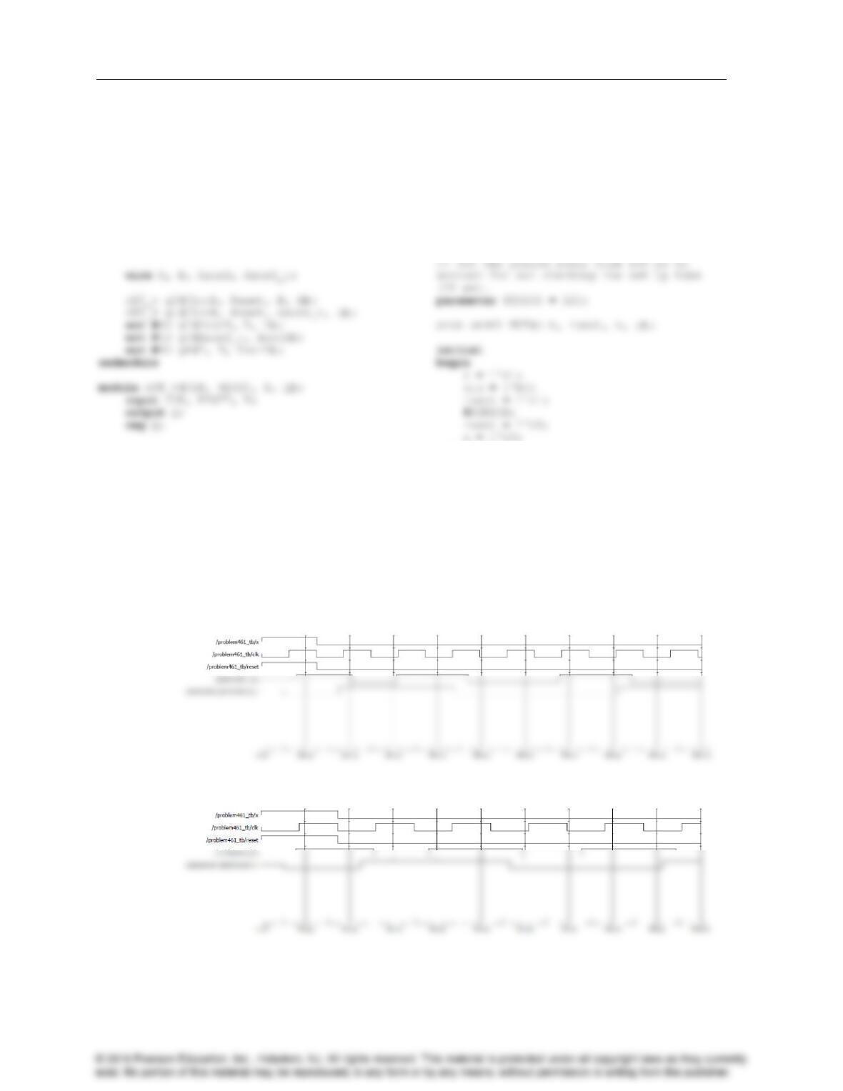
a) The longest direct path delay is from input X through the two XOR gates to the output Y.
c) The longest path delay from the positive clock edge is from Flip-flop A through the two XOR gates to the
output Y.
delay pdFF pdXOR
t t 2 t 0.08 2(0.04) 0.16 ns
4-60.
a) The longest direct path delay is from input X through the four XOR gates to the output Y.
c) The longest path delay from the positive clock edge is from the first Flip-flop A through the four XOR
gates to the output Y.
delay pdFF pdXORR
t t 4 t 0.08 4(0.04) 0.24 ns
38
Problem Solutions – Chapter 4
39
4-61.
There are a number of ways to model the timing behavior, but since the book has not gone into great detail
about modeling timing and some of the features of Verilog and VHDL for modeling timing (e.g., Verilog’s
$specify block) and checking for setup/hold time violations, the example below illustrates a simple approach
that does not require knowledge of these features.
`timescale 1ps/1ps
module problem461(Clock, Reset, X, Y);
input Clock, Reset, X;
output Y;
always @(posedge CLK or posedge RESET)
begin
if (RESET)
Q <= 1’b0;
else
Q <= #80 D;
end
endmodule
`timescale 1ps/1ps
module problem461_tb();
reg x, clk, reset;
wire y;
end
always
#(PERIOD/2) clk = ~clk;
endmodule
Incorrect behavior with the clock period set to 125 ps (Output y should toggle between 0 and 1 on every clock cycle with x
set to 0):
Correct behavior with the clock period set to 175 ps: