Problem Solutions – Chapter 4
1
CHAPTER 4
4-1.
4-2.
4-3.
4-4.
exist. No portion of this material may be reproduced, in any form or by any means, without permission in writing from the publisher.
Problem Solutions – Chapter 4
2
4-5.
Present
state
Input
Next
state
Output
A
B
Y
A
B
Z
0
0
0
0
1
1
S0 – 00
S1 – 01
S2 – 10
S3 – 11
d) This machine is a Moore machine.
4-6.
D
C
C
Clock
Clock
D
X
A
B
Y
A
Problem Solutions – Chapter 4
3
Present
state
Inputs
Next
state
Output
A
B
X
Y
A
B
Z
0
0
0
0
0
0
0
1
1
0
0
0
0
0
S0 – 00
S1 – 01
S2 – 10
S3 – 11
Format: XY/Z (X = unspecified)
d) This machine is a Mealy machine.
4-7.*
Present state
Input
Next state
A
B
C
X
A
B
C
0
0
0
0
1
0
0
4-8.
Present state
Inputs
Next state
Output
Q
X
Y
Q
S
0
0
0
0
0
000
001 010
011100
101
110
111
X = 0
01
01/0, 10/0
01/1, 10/1
00/0, 11/0 00/1, 11/1
Format: XY/S
Problem Solutions – Chapter 4
4-9.
Present State
00
01
00
00
01
11
00
01
11
10
10
Input
1
0
0
1
1
0
1
1
1
1
0
4-10.
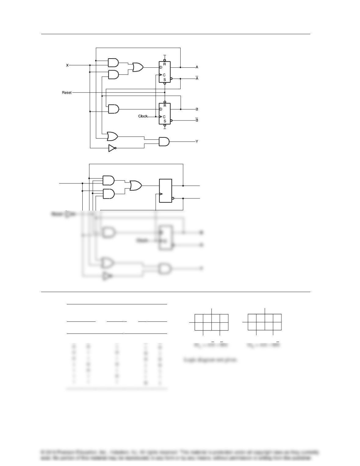
4-11.
A
DB
B
D =X A
Present state
Input
Next state
Output
A
B
X
A
B
Y
0
0
0
01
1/1 0/0
1/0
11/1
00/1
00/0
01/0
0
1
00/1
01/0
10/1
11/0
4
Problem Solutions – Chapter 4
5
4-12.
4-13.*
Present
state
Input
Next
state
A
B
X
A
B
0
0
0
A
B
X
A
B
X
DADB
1
111
1
11 1
b)
D
C
D
C
Y
A
A
X
a)
Vdd
Vdd
Problem Solutions – Chapter 4
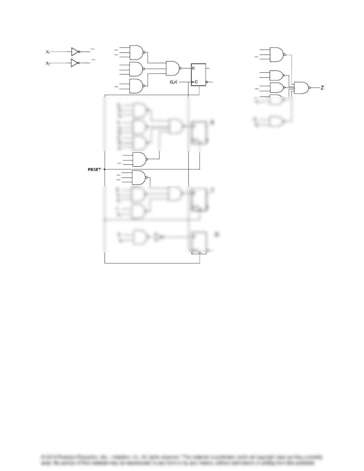
4-14.
For part a) results, replace codes in table below with state name, e.g., 00 with A.
6
Problem Solutions – Chapter 4
7
d)
S
A
X1
X2
C
B
A
X1
X2
X1
X2
A
X1
X2
C
X1
D
X1
X2
X1
X2
D
A
X1
X2
B
X1
C
X2
A
X1
X2
A
X1
X2
D
X1
X2
D
X2
D
X1
Problem Solutions – Chapter 4
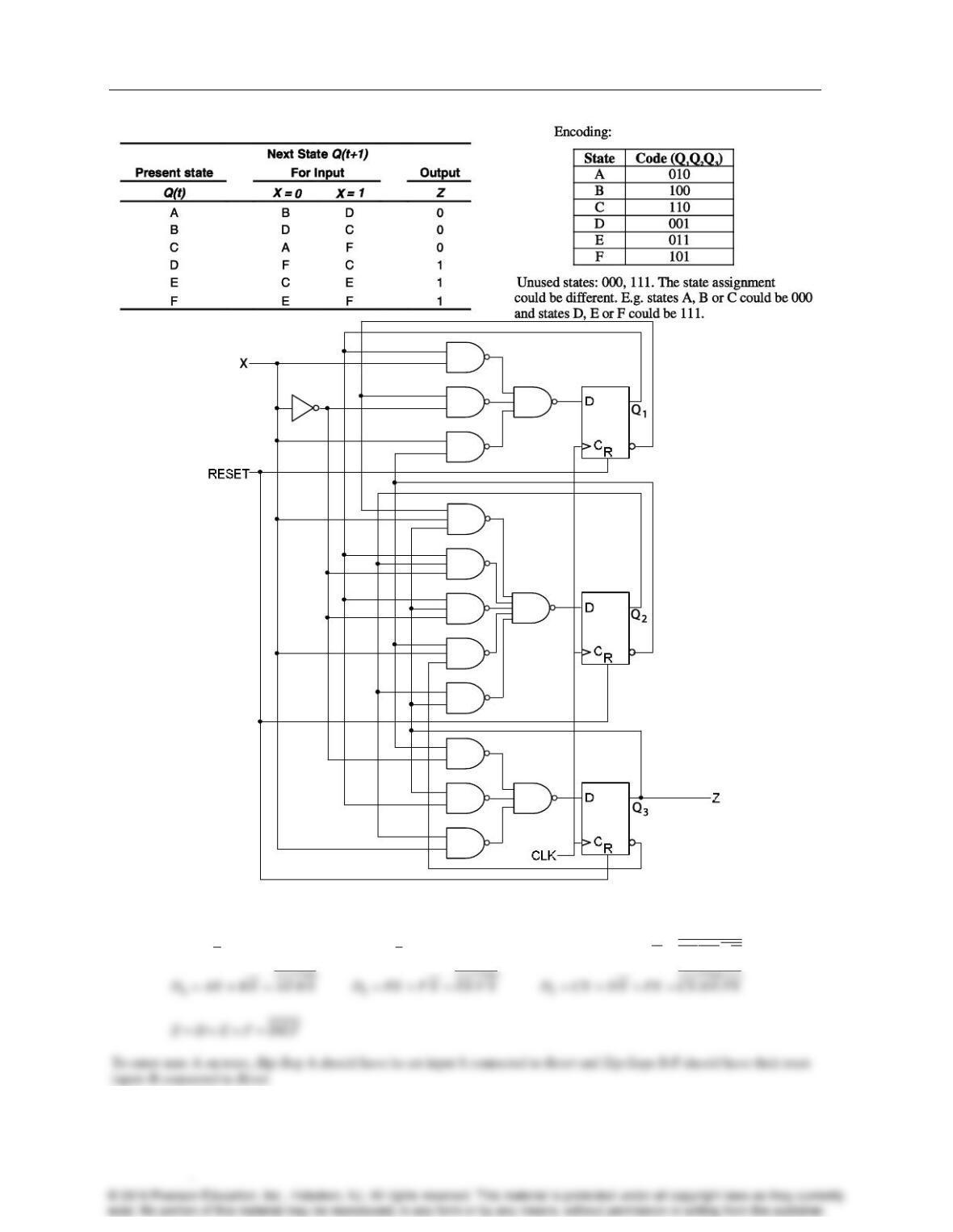
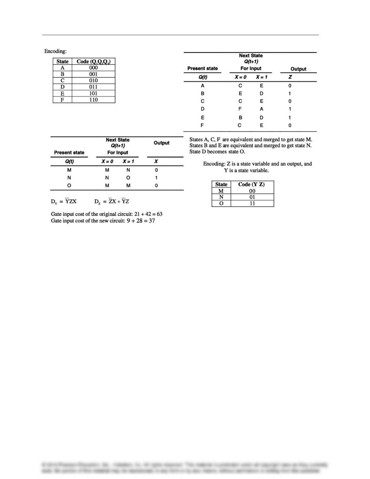
4-15.
d) Using equations for the circuit rather than a schematic:
A
D CX
B
D AX
C
D BX DX E X BX DX E X
8
F
Problem Solutions – Chapter 4
9
4-16.
Problem Solutions – Chapter 4
10
4-17.
Problem Solutions – Chapter 4
11
4-18.*
Format: XY/Z (x = unspecified)
Present
state
Inputs
Next
state
Output
Q(t)
X
Y
Q(t+1)
Z
0
0
0
0
0
c)
// Serial 2s complementer: Verilog Process Description
// problem 4–18 c, 5th edition
// state register: implements positive edge–triggered
// state storage with asynchronous reset.
always @(posedge CLK or posedge RESET)
begin
if (RESET)
end
// output function: implements output as function
// of X, Y, and state
always @(X or Y or state)
begin
case (state)
state0:
case ({X,Y})
2’b00: Z = 1’b0;
01
x1/x
00/0
x1/x
00/1
10/0
Problem Solutions – Chapter 4
12
4-19.
Present
state
Inputs
Next
state
Output
Q(t)
X
Y
Q(t+1)
Z
0
c)
// Serial odd parity generator: Verilog Process Description
// problem 4–19 c, 5th edition
module serial_odd_parity_generator (CLK, RESET, X, Y, Z);
input CLK, RESET, X, Y;
output Z;
reg state, next_state;
parameter state0 = 1’b0, state1 = 1’b1;
reg Z;
// next state function: implements next state as function
// of X, Y and state
always @(X, Y or state)
begin
case (state)
state0: next_state = ({X,Y} == 2’b10) ? state1: state0;
state1: next_state = ({X,Y} == 2’b00) ? state1: state0;
endcase
00/1
00/0
10/1
Format: XY/Z (x = unspecified)
x1/x
10/0
x1/x
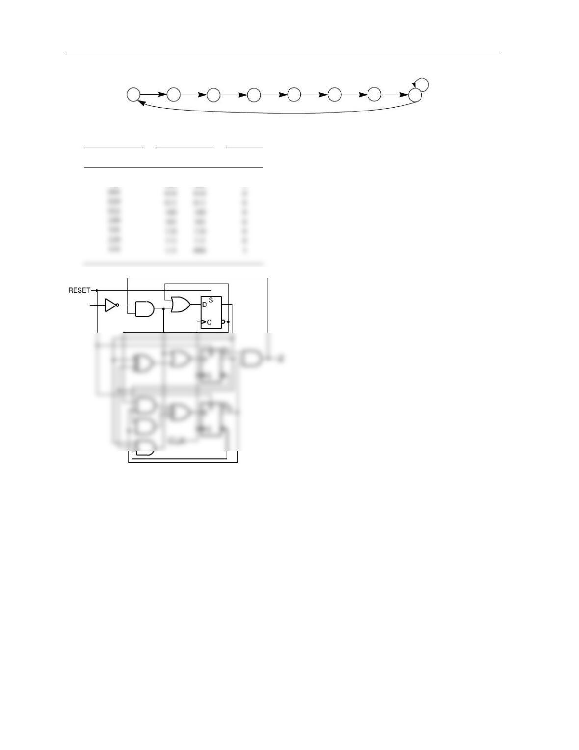
Problem Solutions – Chapter 4
13
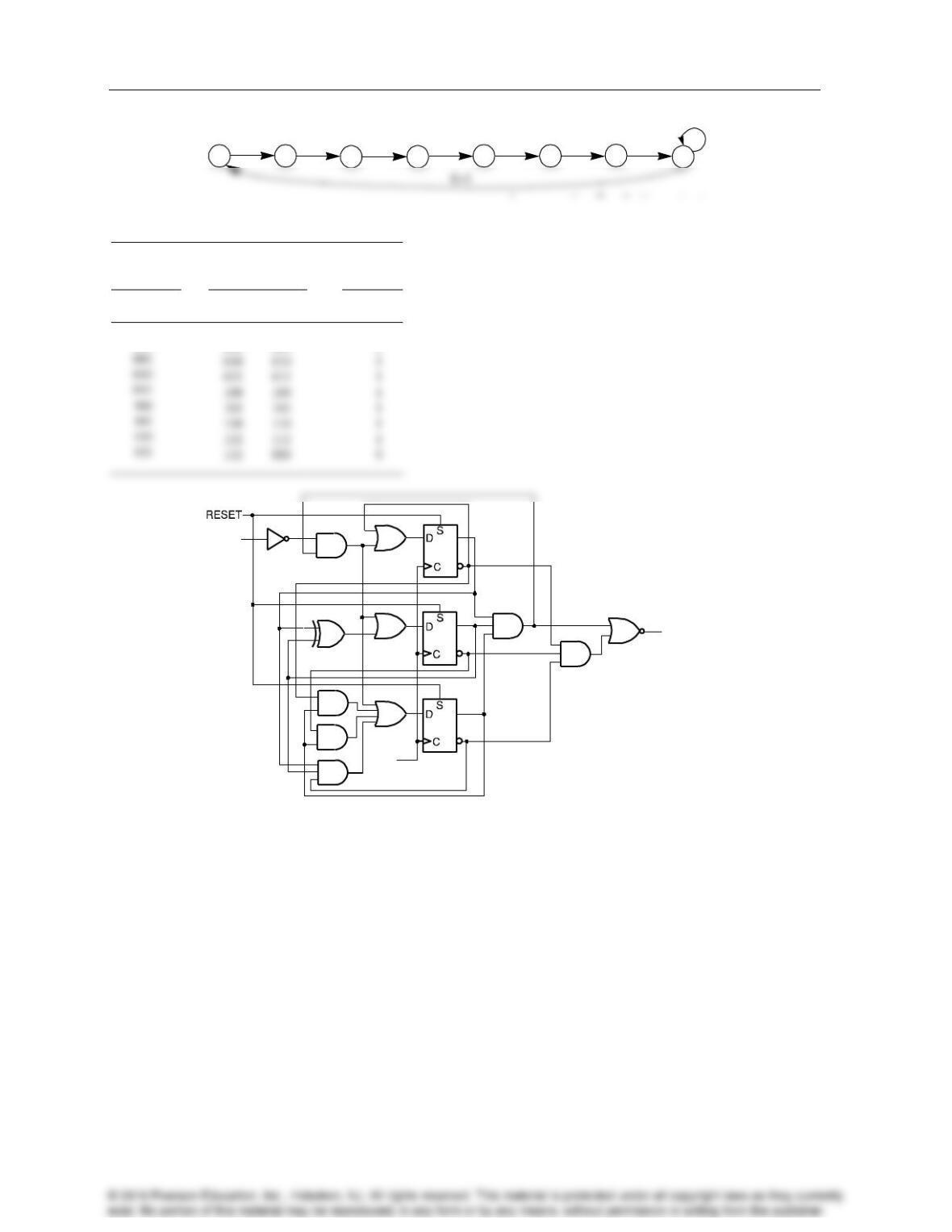
4-20.
Present state
Next State
For Input
Output
D2D1D0
E=0
E=1
Z
000
001
001
0
The state assignment could be different. E. g.,
state 7 could be 000 with state 0 001. This would
permit use of R inputs on the D flip-flops for
RESET.
0/0 7/1
6/0
4/0
3/02/0
1/0 5/0
E=0
E=1
ED0
© 2016 Pearson Education, Inc., Hoboken, NJ. All rights reserved. This material is protected under all copyright laws as they currently
exist. No portion of this material may be reproduced, in any form or by any means, without permission in writing from the publisher.
Problem Solutions – Chapter 4
14
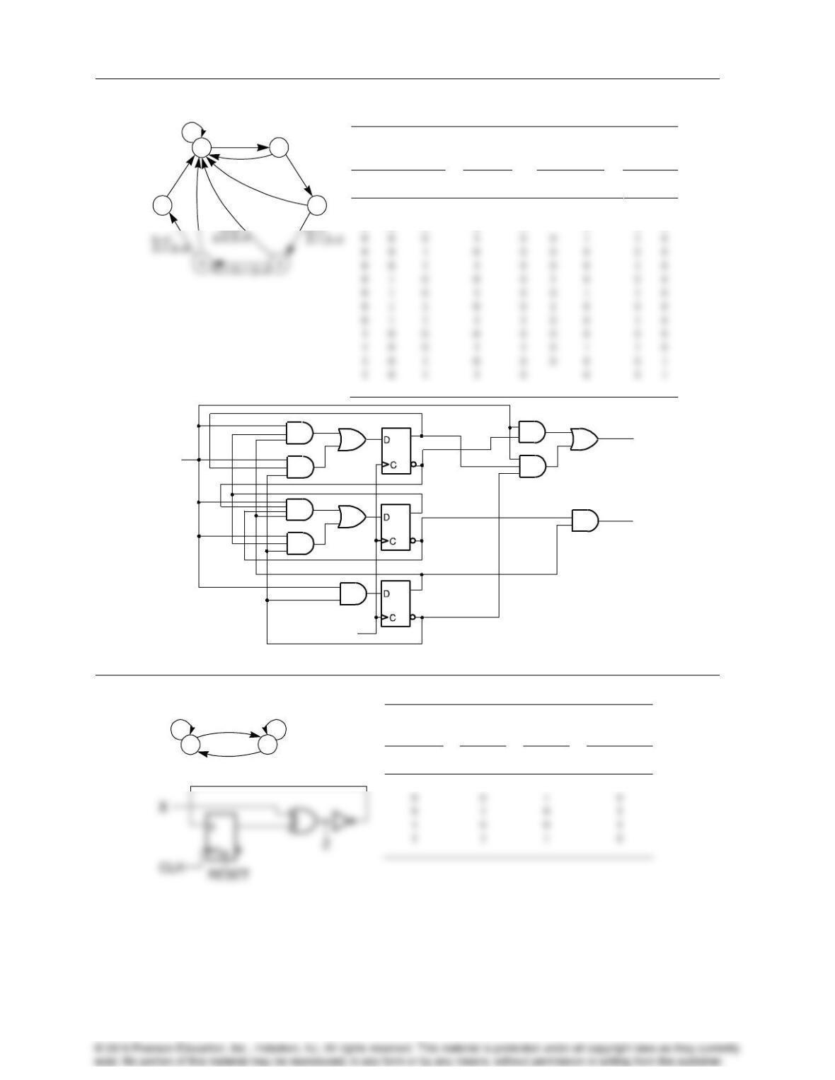
4-21.
Present
state
Next State
For Input
Output
D2D1D0
E=0
E=1
Z
000
001
001
0
Assumes for E = 0, the output remains at 0.
0/0 7/0
6/1
4/1
3/12/1
1/1 5/1
E=0
CLK
Z
E
Problem Solutions – Chapter 4
15
4-22. +
Present state
Input
Next
state
Output
A
B
C
X
A
B
C
Z
S
0
0
0
0
0
0
0
0
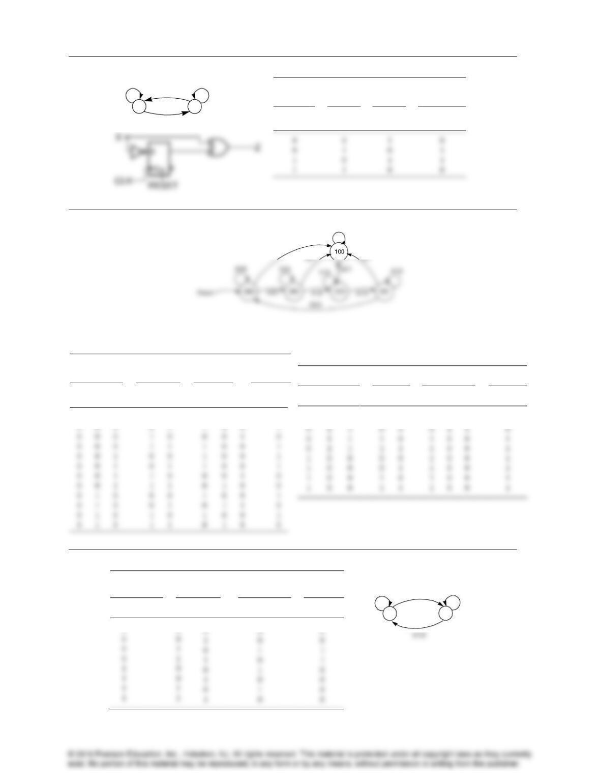
4-23.
Present
state
Input
Next
state
Output
A
X
A
Z
0
2
1
5
X=1/Z=1,S=0
X=1/
Z=1,S=0
X=x/
Z=0,S=1
X=0/Z=0,S=0
X=0/
Z=0,S=0
X=0/
Z=0,
S=0
X=0/Z=0,S=0
CLK
Z
X
S
0 1
X=0 / Z=1
X=0 / Z=0
X=1 / Z=0X=1 / Z=1
Problem Solutions – Chapter 4
16
4-24.+
Present
state
Input
Next
state
Output
A
X
A
Z
4-25.
Present
state
Inputs
Next
state
Output
B
C
D
R
A
B
C
D
E
0
0
0
0
0
0
0
0
0
Present state
Inputs
Next state
Output
B
C
D
R
A
B
C
D
E
0
1
1
0
0
0
0
0
0
4-26.
Present
state
Input
Next state
Output
A
X
Y
A
Z
0
0
Format: XY/Z (x = unspecified)
10
X=1 / Z=0
X=0 / Z=0
X=0 / Z=1X=1 / Z=1
x1/1
xx/1
Format: RA/E (x = unspecif ied)
01
10/1
11/1
0x/0
x0/0
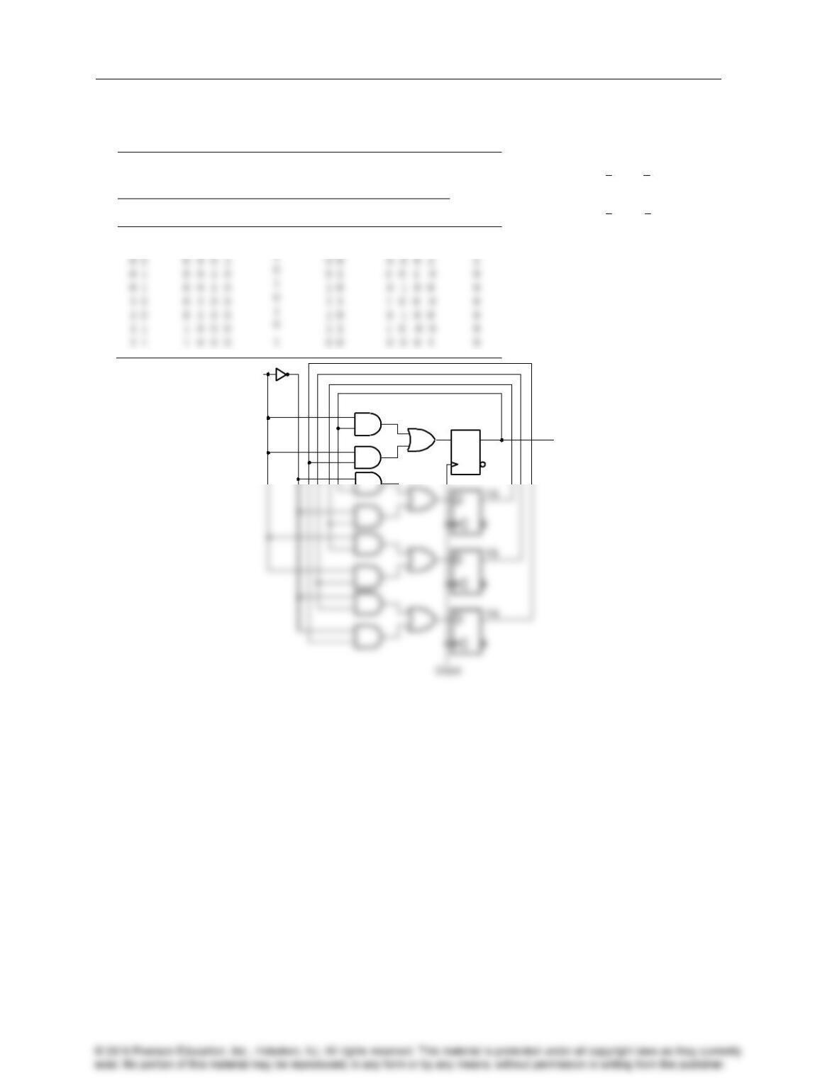
Problem Solutions – Chapter 4
17
4-27.*
To use a one-hot assignment, the two flip-flops A and B need to be replaced with four flip-flops Y4, Y3, Y2. Y1.
Present State
Input
Next State
Output
A B
Y4 Y3 Y2 Y1
X
A’ B”
Y4’Y3’Y2’Y1
Z
0 0
0 0 0 1
0
0 1
0 0 1 0
1
No Reset State Specified.
D1 Y1 X·Y1 X·Y4
D2 Y2 X·Y1 X·Y2
D3 Y3 X·Y2 X·Y3
D4 Y4 X·Y3 X·Y4
’ B“ Y4’Y3’Y2’Y1
D1 = Y 1’= X·Y 1 + X·Y 4
D2 = Y2’ =
D3 = Y 3’ = X·Y 2 + X·Y 3
D4 = Y4’ =
D
C
X
Y1
Y
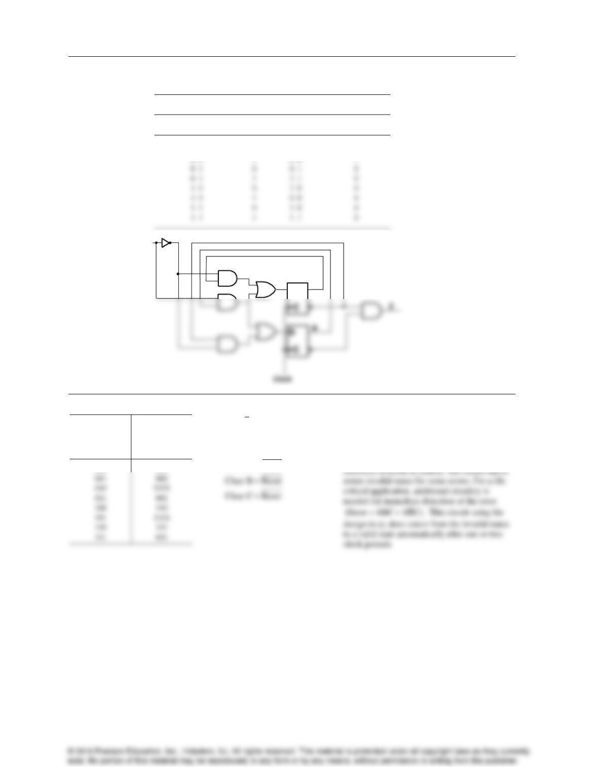
Problem Solutions – Chapter 4
4-28.
Using a Gray code assignment of 00, 01, 11, 10 for states 00, 01, 10, 11, respectively, in the diagram:
Present state
Input
Next state
Output
A B
X
A B
Z
0 0
0
0 1
1
4-29.+
Present
State
Next State
ABC
ABC
000
100
A
B
C
a) D C
DA
DB
b) Clear A Reset
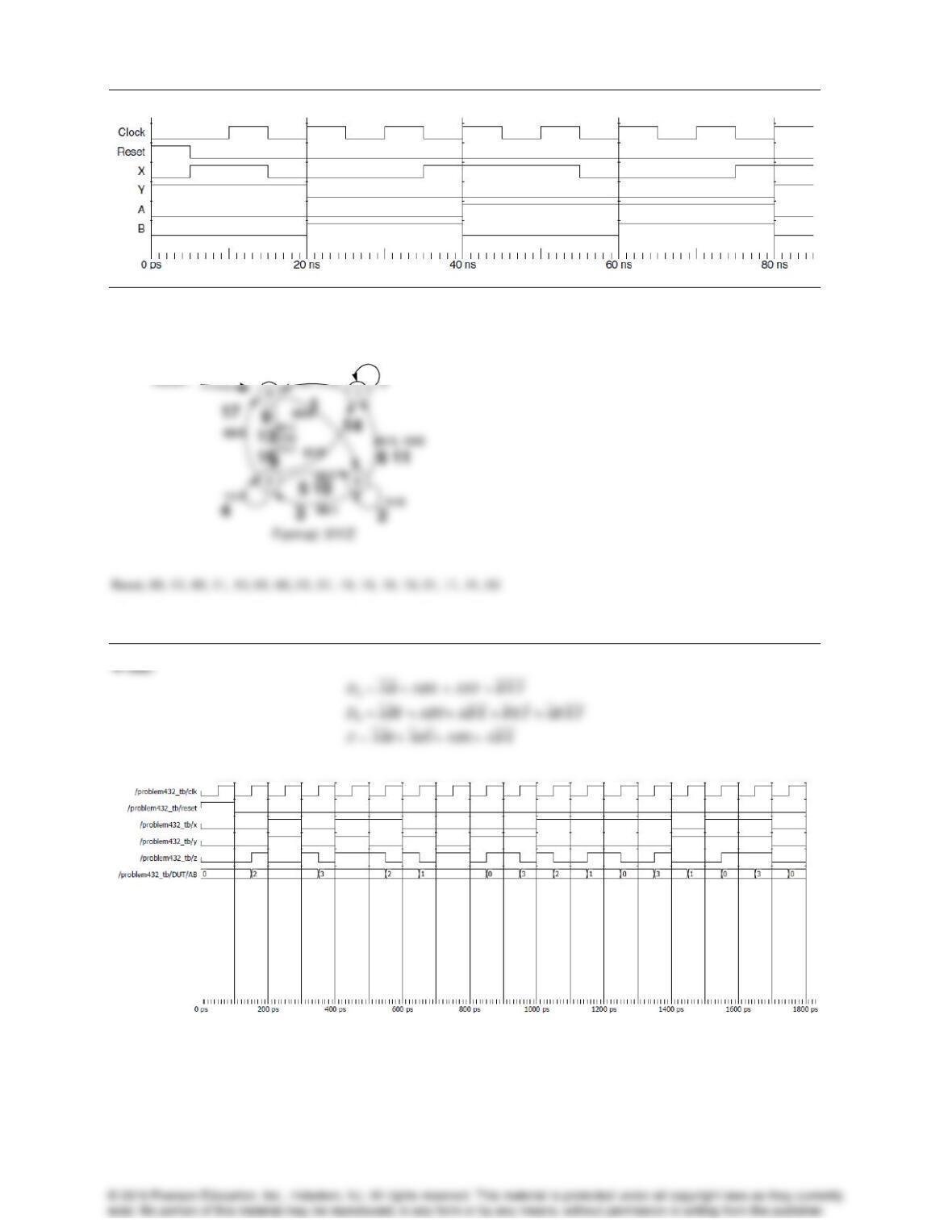
c, d, e, f) The circuit is suitable for child’s toy, but not
for life critical applications. In the case of the
child’s toy, it is the cheapest implementation.
If an error occurs the child just needs to reset
it. In life critical applications, the immediate
D
B
D
X
A
18
Problem Solutions – Chapter 4
19
4-30.
4-31.*
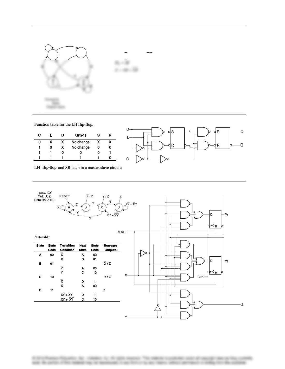
X’s can be used for transitions 8/15 and 9/16, but using X’s would not decrease the length of the sequence.
00/1
01/0
10/1
11/0
8
12
15
11/1
00/0
00/0
01/0
10/1
Problem Solutions – Chapter 4
4-33.
a)
b)
A
D AB BY ABY
4-34.
4-35.
0
1
0
1
1
1
0
20
.
0
0
1
0
1